Video Transmitter - Video transmitter DJI - Free user manual and instructions
Find the device manual for free Video Transmitter DJI in PDF.

User questions about Video Transmitter DJI
0 question about this device. Answer the ones you know or ask your own.
Ask a new question about this device
Download the instructions for your Video transmitter in PDF format for free! Find your manual Video Transmitter - DJI and take your electronic device back in hand. On this page are published all the documents necessary for the use of your device. Video Transmitter by DJI.
USER MANUAL Video Transmitter DJI
DJI Video Transmitter
User Guide
使用说明
使用說明
ユーザーガイド
사용자 가이드
Handbuch
Guía de usuario
Guide d'utilisateur
Guida per l'Utente
natural_image
Technical line drawing of a mechanical device with ports and control knobs (no text or symbols)Contents
EN
Disclaimer 1
Introduction 1
Overview 1
Installation and Connection 3
Activation 7
Linking 8
Display Screen Operations 9
Broadcast Mode Settings 10
Firmware Update 10
Specifications 11
CHS
免责声明和警告 12
简介 12
部件名称 12
安装连线 14
激活 18
对频 19
屏幕操作 20
广播模式设置 21
固件升级 21
规格参数 22
CHT
免責聲明和警告
簡介 23
零組件名稱
安裝連線 25
啟動 29
配對 30
螢幕操作 31
廣播模式設定 32
韌體升級 32
規格參數 33
23
23
JP 免責事項 34
はじめに 34
概要 34
取り付けと接続 36
アクティベーション 40
リンク 41
ディスプレイ画面操作 42
配信モード設定 43
ファームウェア更新 43
仕様 44
KR 고지 사항 45
소개 45
개요 45
설치 및 연결 47
활성화 51
연동 52
디스플레이 화면 조작 53
Broadcast(상송) 모드 설정
펌웨어 업데이트 54
사양 55
Carefully read this entire document and all safety and compliance guidelines provided before use.
Introduction
The DJI™ Video Transmitter uses DJI's O3 Pro Video Transmission technology, which offers a transmission range up to 6 km*, HD video transmission with a bitrate of 40 Mbps, and an end-to-end latency as low as 100 ms. It supports multiple frequency bands in both Control mode and Broadcast mode, as well as one transmitter with multiple receivers, when using with the DJI High-Bright Remote Monitor, meeting the filming requirements of mediums such as movies, TV series, advertisements, and documentaries.
* Measured with the video transmission system in Control mode in an unobstructed environment free of interference that is FCC compliant.
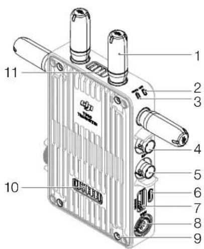
Overview
text_image
Technical diagram of a device with numbered components, likely an electronic or mechanical assembly.
text_image
9 12 13 14 15 16 17 18 19- Detachable Antennas
Transmit wireless signal.
- Linking Status Indicator
Shows the linking status between the receiver and transmitter. Refer to the Linking section for more information on blinking patterns.
- Video Status Indicator
Indicates if there is a video source signal input or not. Solid green indicates input while solid red indicates no input.
- SDI Output Port
Outputs the video source signal from the transmitter.
- SDI Input Port
Inputs the signal from the video source to the transmitter.
6. USB-C Port
For device activation and firmware updates.
7. HDMI Port (Type A)
Receives the video source input signal.
8. DC-in Port
Supplies power to the video transmitter using the provided power cable. Voltage 6-18 V and max current 2 A.
9. M4 Screw Holes
To mount the battery adapter or other adapters for expansion.
10. Power Output Port
Supplies power to an external device.
11. Air Vent
12. Air Intake

DO NOT cover the air vent, air intake, or both sides of the battery adapter if mounted. Otherwise, the performance of the device may be affected due to overheating.
13. Power Button
Press once to power on. Press and hold to power off.
14. Display Screen
Displays the device status and menu.
15. Menu Dial
Turn or press the dial to select or confirm settings in the menu.
16. Back Button
Press to return to the previous screen of the menu.
17. 3/8"-16 Screw Hole
18. 1/4"-20 Screw Holes
19. External Power Input Port
Mount the battery adapter and compatible battery to supply power to the video transmitter.
Installation and Connection
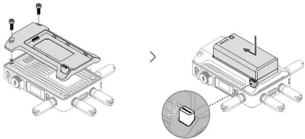
Mounting the WB37 Intelligent Battery
natural_image
Technical illustration showing two views of an electronic device with labeled components and a magnified inset highlighting a component detail (no text or symbols present)Before first use, activate the WB37 battery by charging with the WB37 Battery Charging Hub (USB-C). Refer to the WB37 Battery Charging Hub (USB-C) User Guide for more information.
- Mount the WB37 battery adapter (TX) to the back of the video transmitter and tighten the two M4×12 screws.
- Insert the WB37 battery into the battery slot and push it to the end. Make sure that the battery release button pops up, indicating the battery is firmly in place.

Make sure to use the WB37 battery within the operating temperature range. DO NOT disassemble or pierce the battery in any way. Otherwise, the battery may leak, catch fire, or explode. Refer to the WB37 Intelligent Battery Safety Guidelines for more information.
Press and hold the release button and push the battery in the opposite direction to remove it.
2
text_image
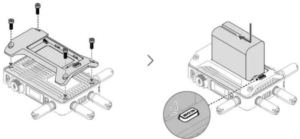
Technical diagram showing assembly of a device with labeled components and a magnified view highlighting the internal component.- Mount the NP-F battery adapter (TX) to the back of the video transmitter and tighten the four M4×12 screws.
- Insert the NP-F series battery into the battery slot and push it to the end. Make sure that the battery release button pops up, indicating the battery is firmly in place.
Press and hold the release button and push the battery in the opposite direction to remove it.
2
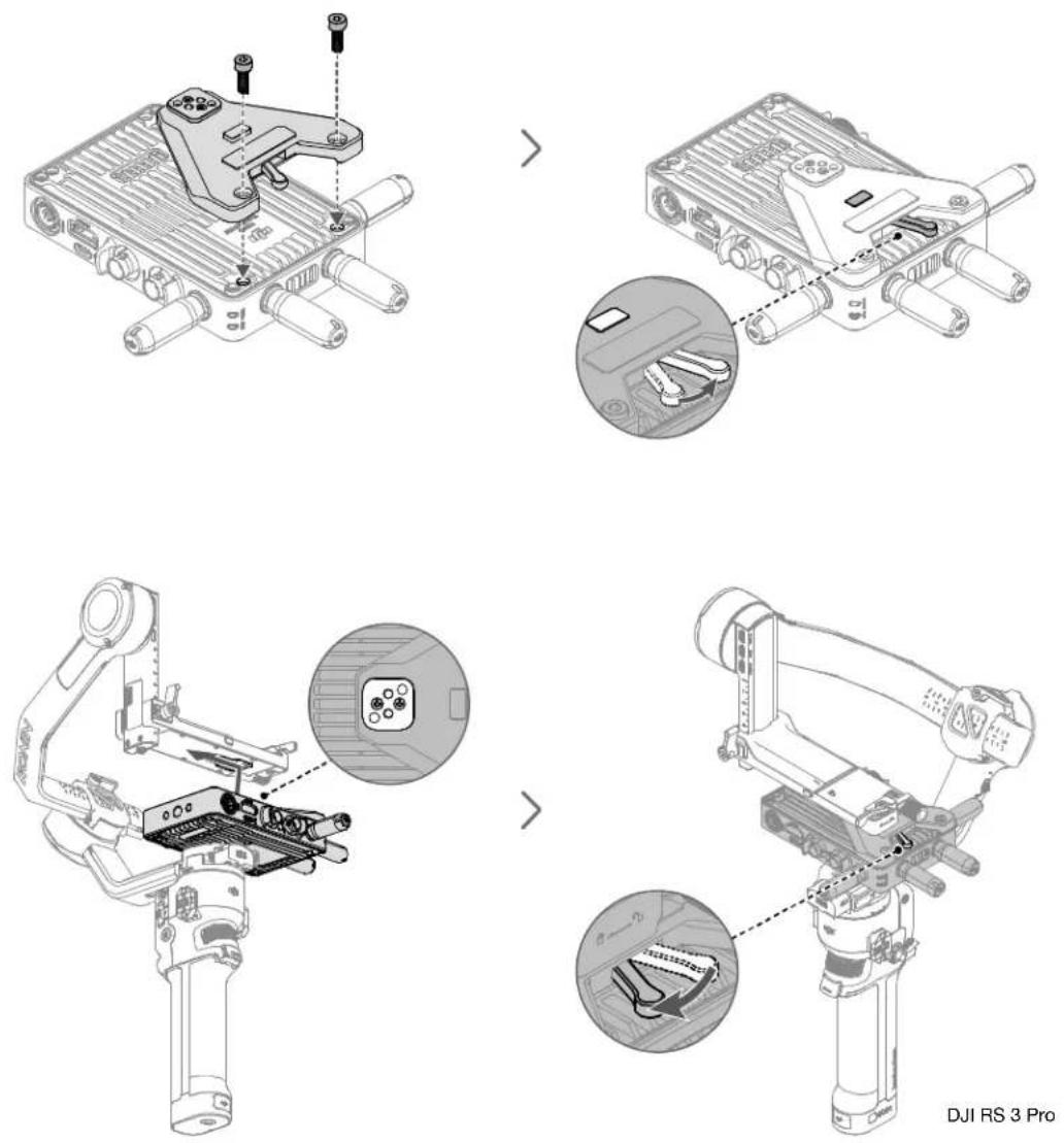
DJI RS 3 Pro
The RS gimbal mounting plate is required when using the video transmitter with the DJI RS series gimbal or other devices compatible with the cold shoe. The following description uses DJI RS 3 Pro as an example.
- Mount the gimbal mounting plate to the front of the video transmitter and tighten the two M4×12 screws.
- Toggle the lever on the gimbal mounting plate in counterclockwise to lower the positioning block.
- Connect the cold shoe on the gimbal mounting plate to DJI RS 3 Pro.
- Toggle the lever on the gimbal mounting plate in clockwise to lock the video transmitter.
Connection
是
DJI Transmission USB-C Power Cable
Connect the video transmission/LiDAR Range Finder port (USB-C) on DJI RS 3 Pro to the DC-in port on the video transmitter for power supply from DJI RS 3 Pro.

natural_image
Technical line drawing of a mechanical robotic device with articulated joints and wiring (no text or symbols)DJI RS 3 Pro
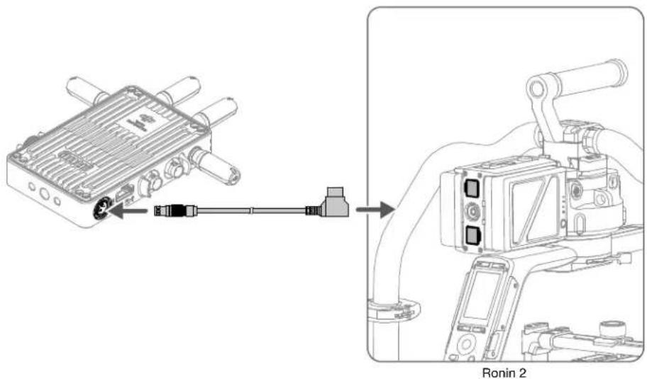
DC to P-Tap Power Cable
Connect the 14.4V P-Tap port on Ronin 2 to the DC-in port on the video transmitter for power supply from Ronin 2.
text_image
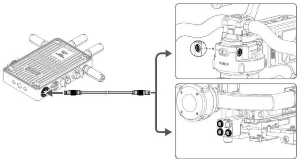
Ia Ronin 2DJI DC Power Cable
Connect the 14.4V accessory power port on the power hub or the port above the pan motor of Ronin 2 to the DC-in port on the video transmitter for power supply from Ronin 2.

When connecting to the port above the pan motor of Ronin 2, the Control mode of the video transmission system is not available.
text_image
Technical diagram showing a connector with labeled parts and its assembly, including a close-up of the internal structure.Ronin 2
Activation
Activation is required when using the video transmitter for the first time. Power on the video transmitter and connect it to the computer using a USB-C cable. Open DJI Assistant 2 (Ronin Series), log in with a DJI account, click the corresponding device icon, and follow the instructions onscreen to activate the device.
Download DJI Assistant 2 from: https://www.dji.com/transmission/downloads
Linking
The video transmitter must be linked to the receiver device before use. The video transmission system of the video transmitter offers Control mode and Broadcast mode, which use different linking methods. Refer to the following section for instructions and linking status indicator descriptions.
Control Mode
- Power on the video transmitter. Press and hold the menu dial on the video transmitter until the linking status indicator blinks red and green alternately, indicating that it is ready to link.
- Power on the remote monitor. Tap to enter System Menu and then Connection Settings. Select Control Mode, set the monitor as Control Monitor A or Control Monitor B, and tap Link to Control Monitor A/B to enter linking status.
- When linking is complete, the linking status indicator turns solid green and the remote monitor will have a connected status.
Broadcast Mode
- Power on the video transmitter. Press the menu dial on the video transmitter, turn the dial to select Broadcast in the menu, enable Broadcast mode, and select channel.
- Power on the remote monitor. Tap to enter System Menu and then Connection Settings. Select Broadcast Mode and the monitor will automatically search for nearby devices with Broadcast mode enabled. Tap a device to monitor and the live view from the corresponding device will display on the remote monitor. Tap the camera number on the right side of the screen to refresh the live view or switch between the monitored devices.
Refer to the Broadcast Mode Settings section for more information about the usage.
Linking Status Indicator
Linking Status Indicator Description
Solid red Device started, not connected.
Blinks red and green alternately Linking.
Solid green Successfully linked in Control mode. Wireless video
transmission is normal.
Broadcast mode enabled.
Blinks red Device malfunction. Contact DJI Support.
Display Screen Operations
E2
Home Screen
text_image
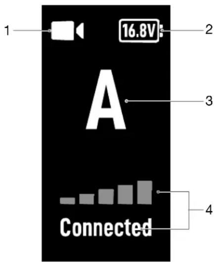
1 16.8V 2 3 A Connected 4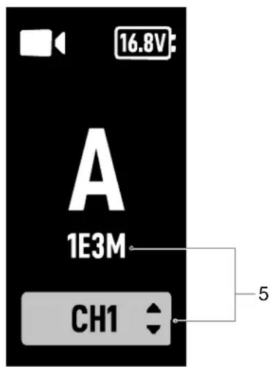
text_image
16.8V A 1E3M CH1 5- Video Signal Input Status
/ : indicates if there is a video source signal input or not.
- Power Supply Voltage
: displays the voltage of the battery or the DC-in power input.
- Device Number
A : displays the device number of the video transmitter. Users can set the number in the menu as the letter A to P.
- Video Transmission Signal Quality and Connection Status
: when Broadcast mode is disabled, it displays the connection status between the receiver and transmitter and the signal quality. There are four statuses, including connected (green), weak signal (orange), strong interference (red), and disconnected (gray).
- Broadcast Code and Channel
1E3M : displays the universally unique identifier of the device when Broadcast mode is enabled for the video transmitter.
CH1 : when the channel mode is set to manual, it displays the channel in use. Press the menu dial twice for quick channel adjustment.
AUTO : when the channel mode is set to auto, this icon will appear. Users cannot adjust the channel manually. When the video transmitter is linked to the remote monitor in Control mode and Broadcast mode is enabled, the channel mode can be set to auto in the remote monitor if Control mode is selected as the prioritized mode.
Menu
In the home screen, press the menu dial on the video transmitter to enter the menu. Users can set the device number, enable Broadcast mode, select Broadcast image quality, select language, and view the video transmission channel status and device information. Turn or press the dial to select or confirm settings in the menu. Press the back button to return to the previous screen.
Broadcast Mode Settings
Broadcast Image Quality
When Broadcast mode is enabled, the Broadcast Quality setting will appear in the menu. Select between HD and Smooth. These two kinds of image quality correspond to 40M (HD) and 20M (Smooth) for the Downlink Bandwidth setting on the remote monitor. When the image quality is set to Smooth, more channels are available than HD.
Mode Priority
When the video transmitter is linked to the remote monitor in Control mode and Broadcast mode is enabled, users can select the prioritized mode in the video transmission channel settings on the remote monitor to ensure transmission signal quality for specific devices.
Broadcast Mode Prioritized
When Broadcast mode is the prioritized mode, the transmission signal quality of the devices in Broadcast mode will have a priority. Users can select the channel manually on the remote monitor and then select the broadcast channel and image quality on the video transmitter.
Control Mode Prioritized
When Control mode is the prioritized mode, the transmission signal quality of the devices in Control mode will have a priority. Users can select the channel mode on the remote monitor and then select the broadcast channel and image quality on the video transmitter. In this mode, devices in Broadcast mode near the remote monitor may have a weak transmission signal.
Firmware Update
Update the video transmitter using the DJI Assistant 2 (Ronin Series) software.
- Power on the device and connect it to a computer with a USB-C cable.
- Launch DJI Assistant 2 (Ronin Series) and log in with a DJI account.
- Select the device and click Firmware Update on the left side of the screen.
- Select the firmware version.
- The firmware will be downloaded and updated automatically.
- The device will restart automatically after the firmware update is complete.
Specifications
| Weight Approx. 350 g (transmitter only, excl. antennas) | |
| Dimensions 127×97×26 mm (excl. antennas) | |
| Operating Frequency[1] | 2.4000-2.4835 GHz, 5.150-5.250 GHz, 5.250-5.350 GHz, 5.470-5.725 GHz, 5.725-5.850 GHz |
| Transmitter Power (EIRP) | 2.4 GHz: <33 dBm (FCC), <20 dBm (CE/SRRC/MIC)5.8 GHz: <33 dBm (FCC/SRRC), <14 dBm (CE)5.1 GHz: <23 dBm (FCC/SRRC/CE/MIC)5.2 GHz: <30 dBm (FCC), <23 dBm (SRRC/CE/MIC)5.5 GHz: <30 dBm (FCC), <23 dBm (CE/MIC) |
| Power Consumption 11 W | |
| Power Supply Voltage | External Power Input Port: 6-18 VDC-In Port: 6-18 V |
| Output Voltage Power Output Port: 6-18 V | |
| Working Time[2] | 3 hours 40 min |
| Input Video Format | 3G SDI: YCbCr 4:2:2 10bitHDMI: RGB 4:4:41080p23.98/24/25/29.97/30/50/59.94/60;1080i50/59.94/60;720p50/59.94/60 |
| Output Video Format | 3G SDI: YCbCr 4:2:2 10bit1080p23.98/24/25/29.97/30/50/59.94/60;1080i50/59.94/60;720p50/59.94/60 |
| Input Audio Format HDMI embedded | |
| Output Audio Format PCM | |
| Video Transmission System O3 Pro | |
| Max Bitrate 40 Mbps | |
| Latency 68 ms (1080p 60fps), 100 ms (1080p 24fps) | |
| Video Coding Format H.264 | |
| Max Transmission Distance | 6 km (FCC), 4 km (CE/SRRC/MIC)(unobstructed, free of interference) |
| Max Communication Bandwidth 40 MHz | |
| Operating Temperature | -10° to 45°C (14° to 113°F) |
[1] Due to local regulations, the 5.1/5.2/5.8GHz frequencies are prohibited in some countries and the 5.1/5.2GHz frequencies are only allowed for use indoors in some countries. 5.600-5.650 GHz is not used.
[2] Tested in a room temperature of 25^ C ( 77^ F) when powered by a fully charged WB37 Intelligent Battery and used with the DJI High-Bright Remote Monitor.
免责声明和警告
natural_image
Technical illustration of a device assembly showing a component being inserted into a box, with a magnified inset highlighting the internal structure (no text or symbols present)text_image
Technical diagram showing assembly of a device with labeled components and a magnified view highlighting a component labeled 'HOTM'.natural_image
Technical line drawing of a mechanical robotic device with no visible text or symbolsDJI RS 3 Pro
DC 转 P-Tap 供电线
text_image
Technical diagram showing a connector assembly with labeled parts and exploded views of the device.Ronin 2
激活
text_image
Technical diagram of a device with numbered components for identification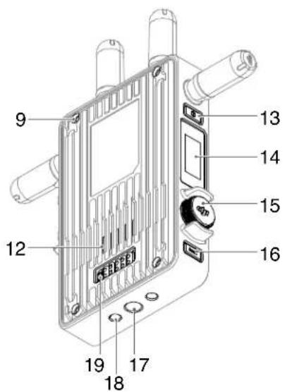
text_image
9 12 13 14 15 16 17 18 19- 可拆卸天線
傳輸無線訊號。
- 配對狀態指示燈
natural_image
Technical illustration showing two views of an electronic device with labeled components and a magnified inset highlighting a component detail (no text or symbols present)text_image
Technical diagram showing assembly of a device with labeled components and a magnified view highlighting the internal component.natural_image
Technical line drawing of a mechanical robotic device with no visible text or symbolsDJI RS 3 Pro
DC 轉 P-Tap 電源線
text_image
Technical diagram showing a device connected to a mechanical assembly with labeled parts and directional arrows indicating connection.Ronin 2
啟動
text_image
Technical diagram of a device with numbered components for identification
text_image
9 12 13 14 15 16 17 18 19- 脱着可能なアンテナ
無線信号を伝送します。
- リンクステータス インジケーター
natural_image
Exploded view diagram of a mechanical assembly with no visible text or symbols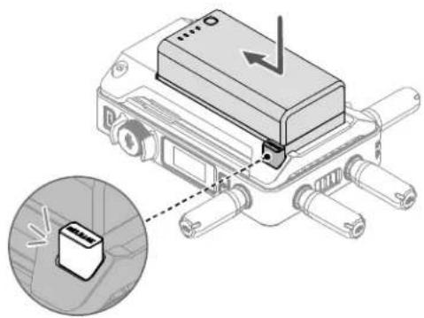
natural_image
Technical illustration of a mechanical device with a highlighted component and a magnified inset showing a small component (no text or symbols present)natural_image
Exploded view diagram of a mechanical assembly with multiple cylindrical components and mounting holes (no text or labels)
text_image
Technical diagram showing a device with a labeled component and an inset image of a device with Chinese text 'RPT100'.natural_image
Technical illustration of an electronic component with mounting holes and a central clamp (no text or symbols)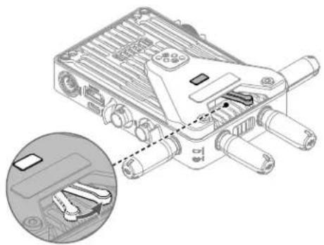
natural_image
Technical illustration of a mechanical device with internal components and a magnified inset showing internal wiring (no text or symbols)
natural_image
Technical line drawing of a robotic arm with a close-up inset showing internal components (no text or symbols)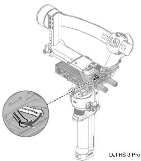
natural_image
Technical line drawing of a DJI RS 3 Pro robotic arm with an inset close-up showing internal components (no text or symbols)DJI RS 3 Pro
natural_image
Technical line drawing of a robotic arm with articulated joints and wiring (no text or symbols)DJI RS 3 Pro
DC - P-Tap電源ケーブル
text_image
Technical diagram showing a connector assembly with labeled parts and exploded views of internal components.Ronin 2
アクティベーション
DJI Assistant 2 https://www.dji.com/transmission/downloads
リンク
text_image
1 16.8V 2 3 4 Connected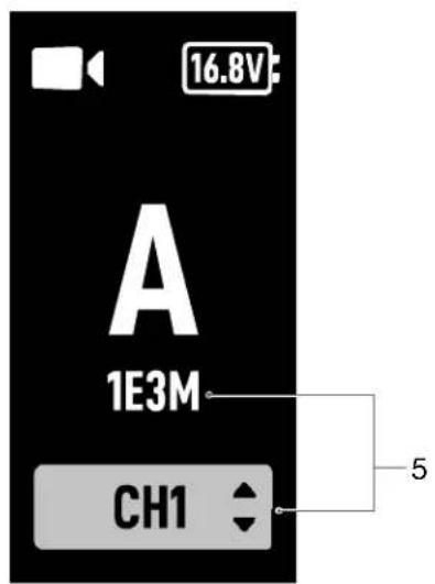
text_image
16.8V A 1E3M CH1 51. 動画信号入力ステータス
text_image
Technical diagram of a device with numbered components, likely an electronic or mechanical assembly.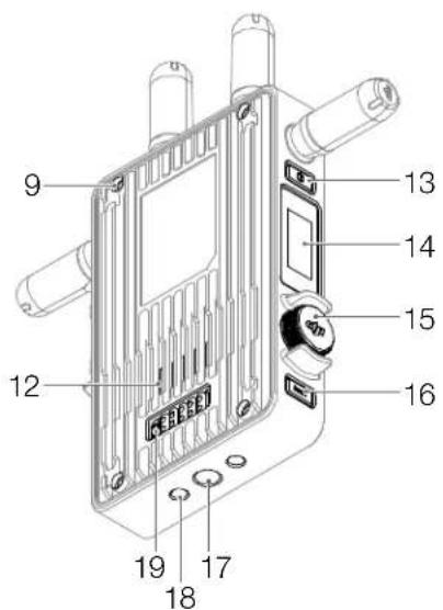
text_image
9 12 13 14 15 16 17 18 19- 탈착형 안테나
무선 신호를 전송합니다
- 연동 상태 표시등
natural_image
Exploded view diagram of a device chassis with labeled components (no text or symbols present)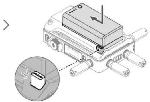
natural_image
Diagram of a device with a rectangular component and a magnified inset showing a small electronic component (no text or symbols present)natural_image
Exploded view diagram of a mechanical assembly with multiple cylindrical components and mounting holes (no text or labels)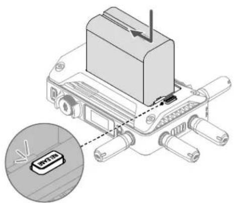
text_image
Technical diagram showing a device with a labeled component and an inset close-up of its internal structure.natural_image
Technical illustration of an electronic device with mounting holes and a central switch (no text or symbols)
natural_image
Technical illustration of an electronic device with internal components and a magnified inset showing internal wiring (no text or symbols)
natural_image
Technical line drawing of a robotic arm with a close-up inset showing internal components (no text or symbols)
natural_image
Technical diagram of a mechanical assembly with an inset showing a component detail (no text or symbols present)DJI RS 3 Pro
natural_image
Technical line drawing of a mechanical assembly with no visible text or symbolsDJI RS 3 Pro
text_image
1o Ronin 2DJI DC 전원 케이블
text_image
Technical diagram showing a connector assembly with labeled parts and exploded views of internal components.Ronin 2
활성화
DJI Assistant 2 다운로드: https://www.dji.com/transmission/downloads
연동
text_image
1 16.8V 2 3 4 Connected
text_image
16.8V A 1E3M CH1 51. 동영상 신호 입력 상태
text_image
Technical diagram of a device with numbered components for identification
text_image
9 12 13 14 15 16 17 18 19- Abnehmbare Antennen
natural_image
Technical illustration showing two views of an electronic device with labeled components and a magnified inset highlighting a component detail (no text or symbols present)natural_image
Exploded view diagram of a mechanical assembly with multiple cylindrical components and mounting holes (no text or labels)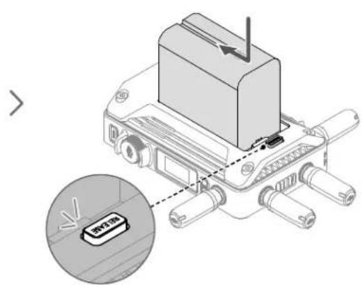
text_image
Diagram showing a device with a labeled component and an inset highlighting a device with 'RPT30' label.natural_image
Technical line drawing of a mechanical device with articulated joints and wiring (no text or symbols)DJI RS 3 Pro
text_image
Technical diagram showing a device connected to an internal component with labeled parts and a close-up view of the internal structure.Ronin 2
Aktivierung
Lade DJI Assistant 2 herunter: www.dji.com/transmission/downloads
Kopplung
text_image
1 16.8V 2 3 A Connected 4
text_image
16.8V A 1E3M CH1 5text_image
Technical diagram of a device with numbered components for identification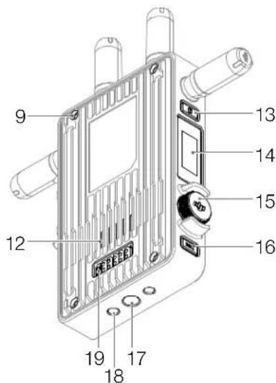
text_image
9 12 13 14 15 16 17 18 19- Antenas extraíbles
natural_image
Technical illustration showing two views of an electronic device with labeled components and a magnified inset highlighting a component detail (no text or symbols present)text_image
Technical diagram showing assembly of a device with labeled components and a magnified inset highlighting the internal component.natural_image
Technical line drawing of a mechanical device with articulated arms and wiring (no text or symbols)DJI RS 3 Pro
text_image
Technical diagram showing a mechanical component connected to an engine, with close-up views of the internal structure.Ronin 2
Activación
Descargue DJI Assistant 2 desde: https://www.dji.com/transmission/downloads
Vinculación
text_image
1 16.8V 2 3 A Connected 4
text_image
16.8V A 1E3M CH1 5natural_image
Technical illustration showing two views of an electronic device with labeled components and a magnified inset highlighting a component detail (no text or symbols present)text_image
Technical diagram showing assembly of a device with labeled components and a magnified inset highlighting the internal component.natural_image
Technical line drawing of a mechanical robotic device with articulated joints and wiring (no text or symbols)DJI RS 3 Pro
text_image
Technical diagram showing a device connected to an I/O motor, with close-up views of the internal components.Ronin 2
Activation
text_image
1 16.8V 2 A 3 4 Connected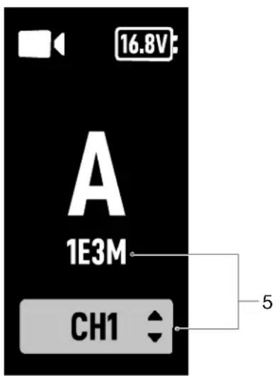
text_image
16.8V A 1E3M CH1 5natural_image
Technical illustration showing two views of an electronic device with labeled components and a magnified inset highlighting a component detail (no text or symbols present)text_image
Technical diagram showing assembly of a device with labeled components and a magnified view highlighting the internal component.natural_image
Technical line drawing of a mechanical device with articulated arms and wiring (no text or symbols)DJI RS 3 Pro
text_image
Technical diagram showing a mechanical component connected to a valve, with close-up views of the internal structure and labeled parts.Ronin 2
Attivazione
Scaricare DJI Assistant 2 da: https://www.dji.com/transmission/downloads
Collegamento
text_image
1 16.8V 2 3 A Connected 4
text_image
16.8V A 1E3M CH1 5text_image
Technical diagram of a device with numbered components, likely an electronic or mechanical assembly.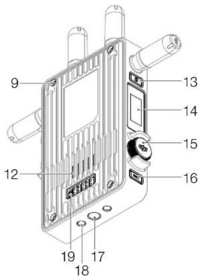
text_image
9 12 13 14 15 16 17 18 19- Afneembare antennes
natural_image
Technical illustration showing two views of an electronic device with labeled components and a magnified inset highlighting a component detail (no text or symbols present)text_image
Technical diagram showing assembly of a device with labeled components and a magnified view highlighting the internal component.natural_image
Technical line drawing of a mechanical device with articulated joints and wiring (no text or symbols)DJI RS 3 Pro
text_image
Technical diagram showing a device connected to an internal component with labeled parts and a close-up of its internal structure.Ronin 2
Activering
Download DJI Assistant 2 van: https://www.dji.com/transmission/downloads
Koppelen
text_image
1 16.8V 2 3 A Connected 4
text_image
16.8V A 1E3M CH1 5- Status ingang videosignaal
natural_image
Technical illustration showing two views of an electronic device with labeled components and a magnified inset highlighting a component detail (no text or symbols present)text_image
Technical diagram showing assembly of a device with labeled components and a magnified view highlighting the internal component.natural_image
Technical line drawing of a mechanical device with articulated arms and wiring (no text or symbols)DJI RS 3 Pro
text_image
Technical diagram showing a device connected to an I/O motor, with labeled components and wiring connections.Ronin 2
Ativação
Descarregue o DJI Assistant 2 de: https://www.dji.com/transmission/downloads
Ligação
text_image
1 16.8V 2 3 A Connected 4
text_image
16.8V A 1E3M CH1 5- Estado da entrada de sinal de vídeo
text_image
Technical diagram of a device with numbered components for identification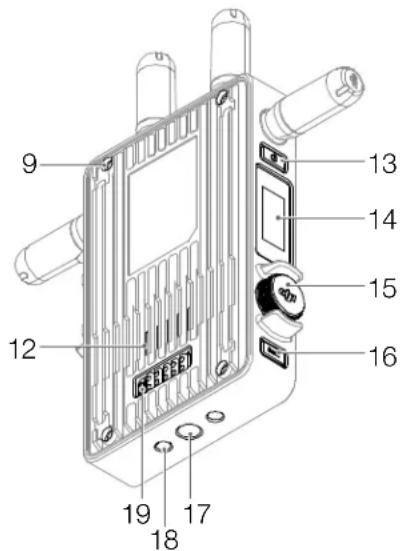
text_image
9 12 13 14 15 16 17 18 191. Съемные антенны
natural_image
Technical illustration showing two views of an electronic device with labeled components and a magnified inset highlighting a small component (no text or symbols present)text_image
Technical diagram showing assembly of a device with labeled components and a magnified view highlighting the internal component.RU
natural_image
Technical illustration of a mechanical component with mounting holes and a handle (no text or symbols)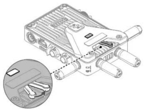
natural_image
Technical illustration of a mechanical device with internal components and a magnified inset showing internal parts (no text or symbols)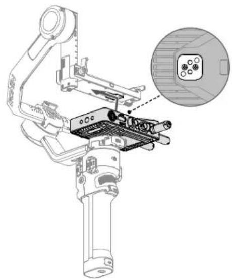
natural_image
Technical line drawing of a robotic arm with internal components and an inset close-up showing a connector detail (no text or symbols)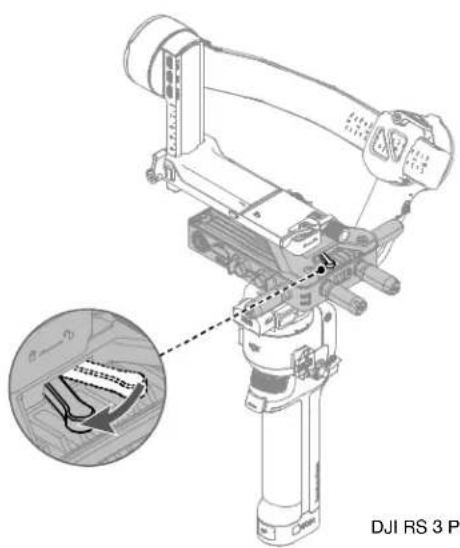
natural_image
Technical diagram of a robotic arm with an inset showing internal components (no text or symbols)DJI RS 3 Pro
natural_image
Technical line drawing of a mechanical device with articulated arms and wiring (no text or symbols)DJI RS 3 Pro
text_image
Technical diagram showing a mechanical component connected to an engine, with close-up views of the internal structure.Ronin 2
Активация
text_image
1 16.8V 2 A 3 Connected 4
text_image
16.8V A 1E3M CH1 5Supplier's Declaration of Conformity
Product name: DJI Video Transmitter
Model Number: TX3
Responsible Party: DJI Technology, Inc.
Responsible Party Address: 201 S. Victory Blvd., Burbank, CA 91502
Website: www.dji.com
We, DJI Technology, Inc., being the responsible party, declares that the above mentioned model was tested to demonstrate complying with all applicable FCC rules and regulations.
This device complies with Part 15 of the FCC Rules. Operation is subject to the following two conditions: (1) This device may not cause harmful interference, and (2) This device must accept any interference received, including interference that may cause undesired operation.
Any changes or modifications not expressly approved by the party responsible for compliance could void the user's authority to operate the equipment.
This equipment has been tested and found to comply with the limits for a Class 3 digital device, pursuant to part 15 of the FCC Rules. These limits are designed to provide reasonable protection against harmful interference in a residential installation. This equipment generates, uses and can radiate radio frequency energy and, if not installed and used in accordance with the instructions, may cause harmful interference to radio communication s. However, there is no guarantee that interference will not occur in a particular installation. If this equipment does cause harmful interference to radio or television reception, which can be determined by turning the equipment off and on, the user is encouraged to try to correct the interference by one or more of the following measures:
—Recurrent or relocate the receiving antenna.
—Increase the separation between the equipment and receiver.
—Connect the equipment into an outlet on a circuit different from that to which the receiver is connected.
—Consult the dealer or an experienced radio/TV technician for help.
RF Exposure Information
This equipment complies with FCC radiation exposure limits set forth for an uncontrolled environment. End user must follow the specific operating instructions for satisfying RF exposure compliance. This transmitter must not be co-located or operating in conjunction with any other antenna or transmitter.
The portable device is designed to meet the requirements for exposure to radio waves established by the Federal Communications Commission (USA). These requirements set a SAR limit of 1.6 W/kg averaged over one gram of tissue. The highest SAR value reported under this standard during product certification for use when property worn on the body.
ISED Compliance Notice
This device contains licence-exempt trans mitter(s)/receiver(s) that comply with Innovation, Science and Economic Development. Canada's licence-exempt RSS(s). Operation is subject to the following two conditions: (1) This device may not cause interference; (2) This device must accept any interference, including interference that may cause undesired operation of the device.
This equipment complies with PSS-102 radiation exposure limits set forth for an uncontrolled environment. End user must follow the specific operating instructions for satisfying RF exposure compliance. The transmitter must not be co-located or operating in conjunction with any other antenna or transmitter. The portable device is designed to meet the requirements for exposure to radio waves established by the CNR-102.
These requirements set a SAR limit of 1.6 W/kg averaged over one gram of tissue. The highest SAR value reported under this standard during product certification for use when properly worn on the body.
No operation is permitted for the frequency *5600-5650MHz*
For devices with detachable antenna(sj, the maximum antenna gain permitted for devices in the bands 5150-5350 MHz and 5470-5725 MHz, 5725-5850 MHz shall be such that the equipment still complies with the a.i.r.p. limit as appropriate.
KCC Compliance Notice
NCC Compliance Notice
EU Compliance Statement: SZ DJI Osmo Technology Co., Ltd. hereby declares that this device (DJI Video Transmitter) is in compliance with the essential requirements and other relevant provisions of the Directive 2014/53/EU.
A copy of the EU Declaration of Conformity is available online at www.dji.com/euro-compliance. EU contact addresses: DJI GmbH, Industriestrasse 12, 97618, Nederlauer, Germany
GB Compliance Statement: SZ DJI OSMO TECHNOLOGY CO., LTD. hereby declares that this device (DJI Video Transmitter) is in compliance with the essential requirements and other relevant provisions of Radio Equipment Regulations 2017.
A copy of the GB Declaration of Conformity is available online at www.cjl.com/euro-compliance
Environmentally friendly disposal

Old electrical appliances must not be disposed of together with the residual waste, but have to be disposed of separately. The disposal at the communal collecting point via private persons is for free. The owner of old appliances is responsible to bring the appliances to these collecting points or to similar collection points. With this little personal effort, you contribute to recycle valuable raw materials and the treatment of toxic substances.
CAUTION: RISK OF EXPLOSION IF BATTERY IS REPLACED BY AN INCORRECT TYPE. DISPOSE OF USED BATTERIES ACCORDING TO THE INSTRUCTIONS.
This device is restricted to indoor use when operating in the 5150-5350MHz frequency range in all EU/EFTA membor states, Turkey, and UK.
The Adopted Trademarks HDMI, HDMI High-D definition Multimedia Interface, and the HDMI Logo are trademarks or registered trademarks of HDMI Licensing Administrator, Inc. in the United States and other countries


Cet appareil at sa accessoires se recyclent
https://www.dji.com/transmission/downloads
* This content is subject to change without prior notice.
If you have any questions about this document, please contact
DJI by sending a message to DocSupport@dji.com.

is a trademark of DJI.
Copyright © 2022 DJI All Rights Reserved.