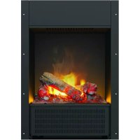
ENG56400 - Fireplace DIMPLEX - Free user manual and instructions
Find the device manual for free ENG56400 DIMPLEX in PDF.



| Product Type | Electric fireplace with flame effect and heating |
| Brand | Dimplex |
| Model | ENG56400 |
| Power Supply | Mains, 230 V AC, 50 Hz (alternating current) |
| Bulb Type | OPTIMYST, 12 V, 45 W, GU5.3 base, 8° beam |
| Main Functions | Realistic flame effect, low and high heating, adjustable thermostat, remote control |
| Thermostat | Continuous adjustment via knob |
| Remote Control | Yes, with 3 buttons (on, medium heat, high heat) |
| Safety | Built-in thermal cutout, mandatory earthing, overheat protection, do not cover |
| Regular Maintenance | Clean the tray, water tank, cap, air filter every 2 weeks |
| Bulb Replacement | Possible, bulbs 12 V 45 W GU5.3 |
| Water Use | Filtered tap water only (not distilled water) |
| Biocide Treatment | Tank and tray treated with Silver Biocide |
| Warranty | 2 years from purchase date (excluding bulbs) |
| Energy | Electric |
| Flame Generator Type | Ultrasonic (transducer with metal disc) |
| Air Filter | Washable, clean every 2 weeks |
| Safety Distance | Minimum 1 meter from combustible materials |
| Use Environment | Indoor only, protected from direct moisture |
| Control Type | Manual and remote control |
Frequently Asked Questions - ENG56400 DIMPLEX
User questions about ENG56400 DIMPLEX
0 question about this device. Answer the ones you know or ask your own.
Ask a new question about this device
Download the instructions for your Fireplace in PDF format for free! Find your manual ENG56400 - DIMPLEX and take your electronic device back in hand. On this page are published all the documents necessary for the use of your device. ENG56400 by DIMPLEX.
USER MANUAL ENG56400 DIMPLEX
Please read this information guide carefully to be able to safely install, use and maintain your product.
Important Safety Advice
When using electrical appliances, basic precautions should always be followed to reduce the risk of fire, electrical shock and injury to persons, including the following:
1. OVERHEATING
WARNING: In order to avoid overheating, do not cover the heater. Do not place material or garments on the heater, or obstruct the air circulation around the heater. The heater carries a DO NOT COVER warning.
2. DAMAGE.
If the appliance is damaged, check with the supplier before installation and operation.
If the supply cord is damaged it must be replaced by the manufacturer or service agent or a similarly qualified person in order to avoid a hazard.
3. LOCATION
Do not use outdoors.
Do not use in the immediate surroundings of a bath, shower or swimming pool.
Do not locate the heater immediately below a fixed socket outlet or connection box.
Ensure that furniture, curtains or other combustible material are positioned no closer than 1 metre from the heater.
Although this heater conforms with safety standards, we do not recommend its use on deep pile carpets or on long hair type of rugs.
4. PLUG POSITIONING
The appliance must be positioned so that the plug is accessible.
Keep the supply cord away from the front of the heater.
5. USE OF OTHER CONTROLS
Do not use this heater in series with a thermal control, a program controller, a timer or any other device that switches on the heat automatically, since a fire risk exists when the heater is accidentally covered or displaced.
6. UNPLUGGING
In the event of a fault unplug the device.
Unplug the device when not required for long periods.
7. OWNER/USER
This appliance is not intended for use by children or persons with reduced physical, sensory or mental capabilities, or lack of experience and knowledge, unless they have been given supervision or instruction concerning use of the appliance by a person responsible for their safety. Children should be supervised to ensure that they do not play with the appliance.
8. ELECTRICITY
WARNING - THIS APPLIANCE MUST BE EARTHED.
This heater must be used on an AC ~ supply only and the voltage marked on the heater must correspond to the supply voltage.
Before switching on, please read the safety advice and operating instructions.
General Information
Only use fi Itered water in this appliance.
Always ensure that the appliance is sitting on a level surface.
Although this heater complies with safety standards, we do not recommend its use on deep pile carpets or on long hair type of rugs.
Please note: Used in an environment where background noise is very low, it may be possible to hear a sound which is related to the operation of the flame effect. This is normal and should not be a cause for concern.
If this product experiences a power surge for whatever reason the product may cut-out. This is a normal safety feature and the product will resume operation after 30 seconds.
Once installed, never move this appliance or lay on its back, without draining the water from sump and water tank. If you intend not using the appliance for longer than 2 weeks, drain the water from sump and water tank and dry the sump.
The water tank, sump, sump lid, tank cap and air filters must be cleaned once every two weeks, particularly in hard water areas.
The appliance should never be operated if the lamps are not working.
The lamps should be regularly inspected as described under 'Maintenance' and 'Changing lamps'.
The sump and the water tank in this product are treated with a biocidal product, Silver Biocide. This conforms with the latest relevant ISO standard
Installation Instructions
This section describes how to set up your fi re.
BEFORE YOU START
- Ensure that all packing items are removed (read any warning labels carefully) and retain all packing for possible future use e.g. in the event of moving house or returning the appliance to your supplier.
- Before connecting the appliance, check that the supply voltage is the same as that stated on the heater.
Connecting the Transducer Unit + Lamps
- Release the two red tabs by turning them by 90 degrees (Fig 2)
- Lift out the Sump Nozzle (Fig 3)
- Insert lamps into lamp holders (Fig 4), carefully locating the pins into the holes (Fig 4a)
- Push lamps firmly into place
- Place the Transducer Unit into the sump and join the cable to the connector on the sump (Fig 5)
- To ensure that the Transducer Unit is correctly placed in the sump, the tab on the Transducer Unit should be lined up with the moulded recess in the sump (Fig 5a).
- Ensure that the cable is not placed above the disc on the Transducer Unit (Fig 5b). To prevent the cable becoming pinched between the nozzle and the sump, place the cable in the slot in the wall of the sump.
- Replace the Sump Nozzle and secure it by turning the two red tabs by 90 degrees (Fig 6)
Filling the Water Tank
- Place Water Tank in sink and remove cap (turn anti-clockwise to open) (Fig 7)
- Fill Water Tank with filtered tap water only. This is necessary to prolong the life of the flame and smoke producing unit. The water should be filtered through a conventional domestic water filter unit and the filter should be replaced regularly. Distilled water must not be used.
- Screw the cap back on - do not overtighten.
- Place the Water Tank in the Sump, with the tank cap facing down and the flat side of the tank facing outward (Fig 8)
Assembling the fire
- Place the Fuelbed on top of the Water Tank and Mist Nozzle (Fig 9)
Operating the Fire
This section describes how to activate your fire using either the manual controls or remote control.
MANUAL CONTROLS
The manual controls are located beneath the hinged flap. (Fig.10 for Manual Control lay out)
Switch 'A':- Controls the electricity supply to the Fire.
Note: This switch must be in the 'ON' ( I ) position for the Fire to operate either with or without heat.
Switch 'B':- Press once to turn on the flame effect. This will be indicated by an audible beep. Although the main lights operate immediately it will take a further 30 seconds before the flame effect starts.
Press again to give flame effect and half heat. This will be indicated by two beeps.
Press again to give flame effect and full heat. This will be indicated by three beeps.
Press again to return to flame effect only. This will be indicated by one beep.
Press to put fire in to standby mode. This will be indicated by one beep.
Control Knob C:- Controls the Thermostat setting.
Turning the control knob to the left will decrease the temperature setting, turning the control knob to the right will increase the temperature setting.
Control Knob 'D':- Controls the intensity of the fl ame effect.
Turning the control knob to the left increases the flame effect, turning the control knob to the right will decrease the flame effect.
SETTING THE THERMOSTAT
Ensure the fire is plugged in and switch it on to the full heat setting. Turn the Control Knob 'C' fully to the right (max temperature setting) to warm the room rapidly. When the room temperature has reached the desired level, turn the thermostat knob back slowly until you hear the thermostat just click off. The heater will then maintain the room temperature at the chosen level.
Note: Should your heater fail to come on when the thermostat is at a low setting, this may be due to the room temperature being higher then the thermostat setting
THERMAL SAFETY CUT-OUT
A thermal safety cut-out is incorporated in the fan heater to prevent damage due to overheating. This can happen if the heat outlet was restricted in any way. If the cut-out operates, unplug the heater from the socket outlet and allow approximately 10 minutes before reconnecting. Before switching the heater back on remove any obstruction that may be restricting the heat outlet, then continue normal operation.
Caution: In order to avoid a hazard due to inadvertent resetting of the thermal cutout, this appliance must not be supplied through an external switching device, such as a timer, or connected to a switch that is regularly switched on and off by the utility.
GETTING THE DESIRED FLAME EFFECT
- The flame control knob 'D' (Fig.10) may be turned up or down to give a more realistic effect.
- Generally the flames appear more realistic when the flame control is turned down.
- Give the flame generator time to react to changes you may make.
- The fire will use less water if the flame effect is set to a lower level.
- Do not tilt or move the fire while there is water in the tank or sump.
- Make sure that the fire is on a level floor.
On the control panel, Switch A (Fig.10) must be in the 'ON' (I) position in order for the remote control to operate. There are 3 buttons on the remote control. (Fig.12) To operate correctly the remote must be pointed towards the front of the grate. (Fig 17). The remote control functions are as follows:
Press once to turn on Flame effect only.
This will be indicated by one beep.
Press once to turn on Half Heat and Flame Effect.
This will be indicated by two beeps.
Press again to turn on Full Heat and Flame Effect.
This will be indicated by three beeps.

Standby
TH will be indicated by one beep.
Maintenance
GENERAL TIPS
Only use filtered tap water in this appliance.
Always ensure that the appliance is sitting on a level surface.
If you intend not using the appliance for longer than 2 weeks, remove and empty the sump and water tank.
Once installed, never move this appliance or lay on its back, without draining the water from sump and water tank. The appliance should never be operated if the lamps are not working.
The lamps should be regularly inspected as described under 'Changing lamps'.
FILLING THE WATER TANK
When the water tank is empty, the flame and smoke effect shuts off and you will hear 2 audible beeps, follow these steps.
- Press Switch 'A' to (0) (Fig.10)
- Gently lift out the fuelbed and carefully set aside.
- Remove the water tank by lifting upwards and outwards.
- Place the water tank in sink and remove cap, Anti-clockwise to open. (Fig 7)
- Fill tank with filtered tap water only. This is necessary to prolong the life of the flame and smoke producing unit.
The water should be filtered through a conventional domestic water filter unit and the filter should be replaced regularly.
- Screw the cap back on, do not over tighten.
- Return the tank to the sump, with the tank cap facing down and the flat side of the tank facing outward. (Fig 8)
- Gently place the fuelbed back into position. (Fig 9)
- Press Switch 'A' to 'ON' (I) position (Fig.10)
CHANGING LAMPS
If the flame and smoke effect appears grey or colourless it may be that one or more lamps have failed.
You can check for lamp failure as follows.
- Leaving the flame effect on, lift out the fuelbed and water tank.
- It should be possible to view the lamps with the nozzle in place and observe which one needs to be changed.
- Put Switch 'A' in the 'OFF' position, and unplug the fire from the mains.
- Leave the appliance for 20 minutes to allow the lamps to cool down before removing them.
- Remove the sump as described in the Cleaning Section.
- Remove the defective lamp, by gently lifting vertically and disengaging the pins from the lamp holder, (Fig.4 and 4a).
Replace with an OPTIMYST, 12V, 45W, Gu5.3 base, 8^ beam angle, coloured lamp. (Purchased from our your supplier)
- Carefully insert the two pins of the new lamp into the two holes in the lamp holder. Push firmly in place. (Fig.4 and 4a).
- Replace the sump, nozzle, water tank and fuelbed.
CLEANING
Warning - Always press Switch 'A' to the 'OFF' (0) position (Fig.10) and disconnect from the power supply before cleaning the fi re.
We recommend cleaning the following components once every 2 weeks, particularly in hard water areas:-
Water Tank, Sump, Nozzle, Tank cap and seal, Air fi Iter.
For general cleaning use a soft clean duster - never use abrasive cleaners.
To remove any accumulation of dust or fluff the soft brush attachment of a vacuum cleaner should occasionally be used to clean the outlet grille of the fan heater.
Water tank
- Remove water tank, as described earlier, put into sink and empty water.
- Using the supplied brush gently rub the inside surfaces of the cap paying particular attention to the rubber ring in the outer groove and the centre rubber seal.
- Put a small quantity of washing up liquid into the tank, refit the cap and shake well, rinse out until all traces of washing up liquid are gone.
- Refill with filtered tap water only, replace the cap, do not overtighten.
Sump
- Press Switch 'A' to the 'OFF' (0) position
- Gently lift out the fuelbed and place carefully on the ground.
- Remove the water tank by lifting upwards.
- Disconnect the electrical connector, located on the right side of the sump. (Fig.5).
- Release the right sump locking tabs by turning 90^ . This allows the sump to be lifted completely from its location. (Fig. 11)
- Gently lift up the sump, taking care to keep level so as not to spill any water. Sit the assembly in the sink.
- Release the left sump locking tabs by turning 90^ , then lift off the Nozzle. (Fig.3)
- Lift out the transducer and carefully tilt, as shown, so that the liquid drains out of the sump. (Fig.13)
- Put a small amount of washing up liquid into the sump, and using the supplied brush, gently clean all surfaces in the sump and gently clean the transducer including the metal discs located in the top grooved surface. (Fig.14)
- When cleaned, thoroughly rinse the sump with clean water to remove all traces of washing up liquid.
- Clean the Nozzle with the brush and flush out thoroughly with water. (Fig.15)
- Reverse the above steps to reassemble.
Air filter
- Gently lift out the fuelbed and place carefully on the ground.
- Gently slide the air filter upwards out of its plastic holder. (Fig.16)
- Gently rinse with water in the sink and dry with fabric towel before returning.
- Replace the filter making sure that the coarse black filter is facing the front of the fire.
- Replace the fuelbed.
Additional Information
AFTER SALES SERVICE
Your product is guaranteed for two years from the date of purchase. Within this period, we undertake to repair or exchange this product free of charge (excluding lamps & subject to availability) provided it has been installed and operated in accordance with these instructions. Your rights under this guarantee are additional to your statutory rights, which in turn are not affected by this guarantee.
RECYCLING

Electrical products sold within the European Community - At the end of the electrical products useful life, be disposed of with household waste. Please recycle where facilities exist. Check with your Local Authority or retailer for recycling advice in your country.
PATENT/PATENT APPLICATION
Products within the Optimyst range are protected by one or more of the following patents and patent applications:
Great Britain GB 2402206, GB 2460259, GB 2460453, GB 2418014, GB 2465738, GB 2449925, GB 2465537, GB 2455277, GB1020534.2, GB1020537.5, GB1110987.3
United States US 7967690, US 2010299980, US 2011062250, US 2008028648, US 13/167,042
Russia RU2008140317
European EP 2029941, EP 2201301, EP 2315976, EP 1787063, EP07723217.1, EP11170434.2, EP 11170435.9
China CN 101883953, CN 200980128666.2, CN 101057105, CN 101438104
Australia AU 2009248743, AU 2007224634
Canada CA 2725214, CA 2579444, CA 2645939
International Patent Application WO 2006027272
South Africa ZA 200808702
Mexico MX 2008011712
Korea KR 20080113235
Japan JP 2009529649
Brazil BR P10708894-9
India IN 4122/KOLNP/2008
New Zealand NZ 571900
Troubleshooting
| Symptom Cause Corrective Action | ||
| The fl ame effect will not start. | Mains plug is not plugged in. | Check plug is connected to wall socket correctly. |
| Low water level. | Check that the water tank is full and there is water in the sump. | |
| Low voltage connector not connected properly. (Fig.5) | Check that the connector is inserted correctly. (Fig.5) | |
| The Transducer Unit is not sitting correctly in the sump | Ensure the Transducer in sitting down into the moulded recess in the sump | |
| The fl ame effect is too low. | Flame effect control knob is set too low. (Fig.10) | Increase level of fl ame by turning Control knob ‘D’ to the left slowly. (Fig.10) |
| The Metal Disc in the transducer might be dirty (Fig.14) | Clean the Metal Disc with soft brush supplied. (Fig.14) See ‘Maintenance.’ for a step by step procedure. | |
| The wire from the Transducer Unit is sitting over the metal disc | Direct the wire to the back of the sump and make sure it sits into the side slot exiting the sump. | |
| Unpleasant smell when unit is used. | Dirty or stale water. | Clean the unit as described under maintenance. |
| Using unfi itered tap water. | Use only fi itered tap water. | |
| The fl ame effect has too much smoke. | Flame effect setting is too high. | Turn the flame effect Control knob ‘D’ to the right, about ¼ a turn, at a time. Give the fl ame generator some time to adjust to the new setting. (Fig.10) |
| Main lamps are not working and there are no fl ames or smoke. | There is no water in the water tank Follow instructions under Maintenance, ‘Filling the water tank’. Check the plug is connected to the wall socket correctly and that Switch ‘A’ Fig. 10 is in the ‘ON’ (I) position. | |
Einleitung
Bitten i t d.
USA US 7967690, US 2010299980, US 2011062250, US 2008028648, US 13/167,042
REEMPLACEMENT DES AMPOULES
Australia AU 2009248743, AU 2007224634
Caná CA 2725214, CA 2579444, CA 2645939
Mexico MX 2008011712
Corea KR 20080113235
Japon JP 2009529649
Brasil BR P10708894-9
India IN 4122/KOLNP/2008
India: IN 4122/KOLNP/2008
India: IN 4122/KOLNP/2008
WAARSCHUWING - DIT APPARAAT MOET WORDEN GEAARD
OCTROOIEN EN OCTROOIAANVRAGEN
Australia AU 2009248743, AU 2007224634
Canada CA 2725214, CA 2579444, CA 2645939
Mexico MX 2008011712
Korea KR 20080113235
Japan JP 2009529649
Brazilié BR P10708894-9
India IN 4122/KOLNP/2008
USA US 7967690, US 2010299980, US 2011062250, US 2008028648, US 13/167,042
Rusland RU2008140317
Europa EP 2029941, EP 2201301, EP 2315976, EP 1787063, EP07723217.1, EP11170434.2, EP11170435.9
Kina CN 101883953, CN 200980128666.2, CN 101057105, CN 101438104
Australian AU 2009248743, AU 2007224634
Canada CA 2725214, CA 2579444, CA 2645939
International patentansøgning WO 2006027272
Sydafrika ZA 200808702
Mexico MX 2008011712
Korea KR 20080113235
Japan JP 2009529649
Brasilien BR P10708894-9
Indien IN 4122/KOLNP/2008
New Zealand NZ 571900
Fejlsøgning
UK - Warranty The warranty conditions in the country of purchase apply to this appliance. Information can be obtained at any time from the retailer from whom the appliance was purchased. For claims under guarantee the sales receipt must be produced and the claims must be forwarded within the guarantee period. The right to claim under guarantee expires in case that the device has been damaged, used in an inappropriate way or that unauthorized manipulations have been carried out.
- Warranty Card
- Guarantee Period (in Years)
- Model(s)
- Date of Purchase
- Stamp & Signature of retailer
- Fault/Defect
- Contact Number & Address
DE
- Important Safety Advice
- OVERHEATING
- DAMAGE.
- LOCATION
- PLUG POSITIONING
- USE OF OTHER CONTROLS
- UNPLUGGING
- OWNER/USER
- ELECTRICITY
- General Information
- Installation Instructions
- BEFORE YOU START
- Filling the Water Tank
- Assembling the fire
- Operating the Fire
- SETTING THE THERMOSTAT
- THERMAL SAFETY CUT-OUT
- GETTING THE DESIRED FLAME EFFECT
- Maintenance
- GENERAL TIPS
- CHANGING LAMPS
- CLEANING
- Water tank
- Sump
- Air filter
- Additional Information
- AFTER SALES SERVICE
- RECYCLING
- PATENT/PATENT APPLICATION
- Einleitung
- REEMPLACEMENT DES AMPOULES
- OCTROOIEN EN OCTROOIAANVRAGEN
- DE
Brand : DIMPLEX
Model : ENG56400
Category : Fireplace