OS3 - Speaker Mirage - Free user manual and instructions
Find the device manual for free OS3 Mirage in PDF.

| Brand | Mirage |
| Model | OS3 |
| Category | Loudspeaker |
| Technology | Omnipolar |
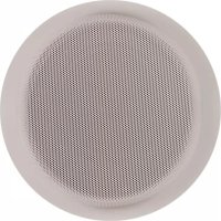
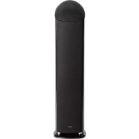
| Speaker type | Passive satellite |
| Usage | Music listening and home cinema |
| Wall mounting | Yes, with dedicated wall mount (included) |
| Ceiling mounting | Possible |
| Connections | High quality terminals (banana plug, spade, bare wire) |
| Cleaning | Damp cloth (disconnect before) |
| Safety | Do not expose to rain or immerse |
| Passive speaker warranty | 5 years |
| Subwoofer warranty | 1 year |
| Included accessories | Wall mount, mounting template (OS3 CC) |
| Recommended orientation | Ear height when seated |
Frequently Asked Questions - OS3 Mirage
User questions about OS3 Mirage
0 question about this device. Answer the ones you know or ask your own.
Ask a new question about this device
Download the instructions for your Speaker in PDF format for free! Find your manual OS3 - Mirage and take your electronic device back in hand. On this page are published all the documents necessary for the use of your device. OS3 by Mirage.
USER MANUAL OS3 Mirage
owners manual
IMPORTANT SAFETY INSTRUCTIONS - READ CAREFULLY !
READ INSTRUCTIONS: All safety and operating instructions should be read before the product is operated.
RETAIN INSTRUCTIONS: Safety and operating instructions should be retained for future reference.
HEED WARNINGS: All warnings on the product & operation instructions should be adhered to.
FOLLOW INSTRUCTIONS: All operating and use instructions should be followed.
CLEANING: Unplug the product from the wall before cleaning. Do not use aerosol or liquid cleaners, just a damp cloth.
DO NOT EXPOSURE THE SPEAKERS TO DIRECT RAINFALL OR SUBMERGE THEM UNDERWATER – PERMANENT DAMAGE WILL RESULT
DAMAGE REQUIRING SERVICE: The product should be serviced by qualified personnel when:
A. The appliance does not appear to operate normally or exhibits a marked change in performance; or
B. Product has been dropped, or the enclosure damaged.
C. If the product does not operate normally by following the operating instructions.
MIRAGE OS ^3 SERIES
Please take the time to read all of the instructions contained in this manual to make certain your system is properly connected and functioning correctly.
Please retain the carton and packing materials for this Mirage product to protect it in the event it ever has to be shipped to a service center for repairs. Product received damaged by a service center that has been shipped by an end user in anything other than the original packaging will be repaired, refurbished, and properly packaged for return shipment at the end user's expense.
INTRODUCTION
We are proud to welcome you as a new owner of a Mirage speaker system. The finest components and materials are manufactured to exacting standards and tested with sophisticated manufacturing and quality control techniques to ensure exceptional performance that is superior to speakers costing several times their price. This approach to the development of the Mirage OS has resulted in a significant improvement over other system designs in terms of performance and aesthetics.
THE OS ^3 SERIES
The main goal of the new OS ^3 was to provide a series of speakers with the most natural, accurate performance that could excel at both home theater and music reproduction. This was accomplished by using Mirage's newest proprietary Omnipolar technology. Omnipolar technology produces the same amount of direct and reflected sound as live events for the most realistic experience of either music or home theater.
WHAT EXACTLY IS OMNIPOLAR?
Omnipolar technology uses natural room reflections to create a greater sense of realism. This is accomplished by recreating the same ratio of direct to reflected sound - 70% reflected and 30% direct, that is typically found in performance spaces. A conventional speaker only produces 30% reflected sound. It is the additional reflected sound provided by a Mirage Omnipolar speaker that creates a miraculous three-dimensional sound experience in your home.
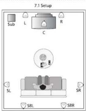
SPEAKER PLACEMENT
The Mirage OS ^3 has been designed for high performance in a wide variety of settings, but here are a few helpful hints that will help to maximize performance and your enjoyment.
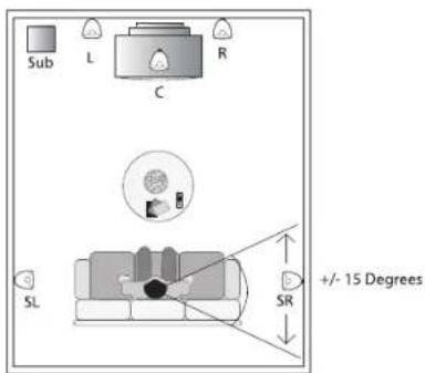
LEFT AND RIGHT CHANNELS
A general guideline for speaker placement is to set up the space between speaker and listener at approximately 1-1/2 times the distance between the speakers. For example, if the speakers were ideally placed a minimum of 6 feet apart, the best seating position would be 9 feet away.
Ideal height would position the speaker at approximately ear level when the listener is in a seated position. For the OS ^3 satellite, this can be accomplished by using the recommended OS ^3 stand.
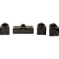
CENTER CHANNEL
A center channel can be expected to reproduce as much as 60% of a movie's soundtrack, most of which is dialogue. In order to maintain the effect of voices emanating from the actor's mouth, the OS ^3 CC should be centrally located between the left and right OS ^3 speakers and be placed above or below the television.
owners manual
SURROUND CHANNEL
The surround speakers should be positioned adjacent to and slightly behind the primary listening area, on the rear or side wall or on the ceiling to provide a sense of spaciousness and ambience for all Surround Sound formats. These speakers should ideally be placed above ear level for best performance. See diagram 3.
MOUNTING OPTIONS
OS ^3 SATELLITE
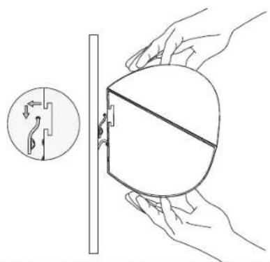
The small size and Omnipolar dispersion of the versatile OS Satellite speakers permits them to be easily wall mounted. The OS Satellite comes equipped with its own specifically designed wall bracket. The bracket allows for two simple installation alternatives:
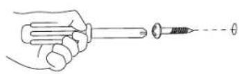
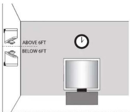
a. Carefully drive a #8 screw into a stud in the wall, leaving approximately 1/4 inch of the screw exposed, then mount the OS ^3 Satellite like you would a picture. Note: Failure to attach the screw safely to a secure spot on the wall can result in damage or injury. When mounting the speaker at a height of under six feet, orient the OS ^3 Satellite in an upright position. Slide the head of the screw into the wide portion of the channel opening and slide the OS ^3 Satellite downward until it sits in position. When mounting the speaker at a height of over six feet, orient the OS ^3 Satellite in an upside down position so the grille is facing the floor and use the bottom key-way channel. Slide the head of the screw into the wide portion of the channel opening and slide the OS ^3 Satellite downward until it sits in position. See Diagrams 2a, 3
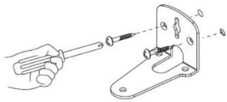
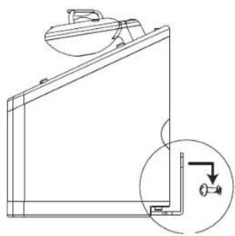
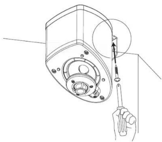
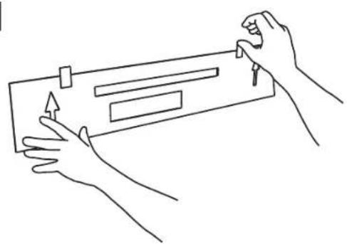
b. Start by marking the bracket's screw positions on the wall with a pencil, then screw the bracket to the wall. Drywall anchors are recommended for any drywall wall mount installation to ensure a solid installation. After the bracket has been mounted to the wall, the OS ^3 Satellite speaker can simply be mounted to the bracket by tightening the included bolt to the bottom of the OS ^3 . See Diagrams 2b, 3
CEILING MOUNT: The OS Satellite speakers can also be ceiling mounted. Please follow the same instructions outlined in section b above.
OS ^3 CC CENTER CHANNEL
- Choose the desired mounting position. If possible, find a position on the wall that allows the OS ^4 CC to be mounted directly to a wall stud. Attach the mounting template (included in the box) to the desired position by using tape or small nails. (Diagram 6)
IMPORTANT: The arrows on the template should point in the same direction as the grill. If the OS ^3 CC is mounted below 6 feet, the grille should face upwards and therefore the arrows on the template should also point upwards. If the OS CC is mounted above 6 feet, the grille should face downwards, and similarly the arrows on the template should also point downwards.
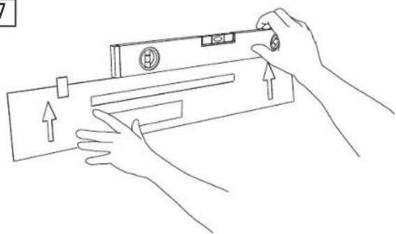
- Using a level, ensure the template is attached level to the wall. It is critical that the template is level as a mistake at this stage will result in uneven mounting of (Diagram 7)
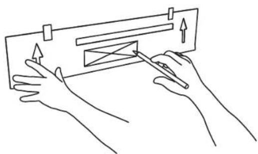
- Outline the two rectangular boxes. Mark the smaller box with an X. The smaller box is needed for the wire management outlining the recommended wall cut-out. (Diagram 8)
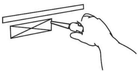
- After the template has been removed, use a drywall saw to cut out the smaller rectangular box marked with an X. Please note that this step is only required if the wires will be fed through the wall. If a different wire management system is being used, please ignore this step. (Diagram 9)
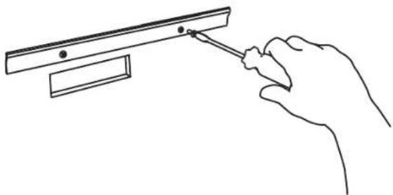
- Mount the wall bracket into position. The use of proper anchors for all screws is required to ensure a secure installation. Please note that screws and anchors are not included in the OS ^3 CC package. (Diagram 10)
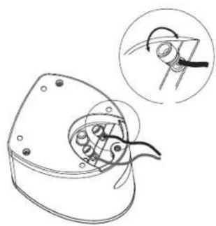
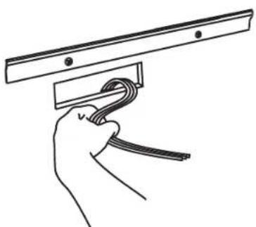
- Feed the wires through the hole cut out. (Diagram 11)
- Connect the wires to the appropriate binding posts at the back of the OS ^3 CC.
IMPORTANT: Connect the speaker wire from the positive (RED +) terminal on the amplifier to the positive (RED+) terminal on the speaker. Connect the negative (BLACK-) terminal on the amplifier to the negative (BLACK-) terminal on the speaker.
- After the wires are connected, hang the OS ^3 CC on the wall bracket. Center the OS ^3 CC and push down lightly on the speaker to achieve a tight fit between the speaker and the bracket. If the speaker is not centered, repeat this step. (Diagram 12)
owners manual
BOOKSHELF/ENTERTAINMENT UNIT PLACEMENT
The small size and Omnipolar dispersion of the versatile OS ^3 Satellite and OS ^3 center channel speakers permits them to be easily placed, among other places, in a bookshelf. To maximize the Omnipolar dispersion potential, bring the speaker as close to the front of the cabinet as possible.
CONNECTIONS
The Mirage OS ^3 series is equipped with high quality binding posts that permit the use of banana plugs, spades, or a bare wire connection. Connect the speaker wire from the positive (RED +) terminal on the amp to the positive (RED+) terminal on the speaker. Connect the negative (BLACK-) terminal on the amplifier to the negative (BLACK-) terminal on the speaker.
natural_image
Technical line drawing of a mechanical component with an inset showing a close-up view of a tool interacting with a curved tool (no text or symbols present)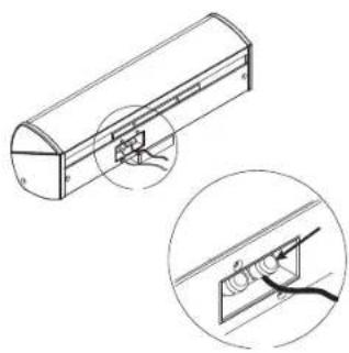
natural_image
Technical line drawing of a mechanical component with an inset showing a close-up view of a component (no text or symbols present)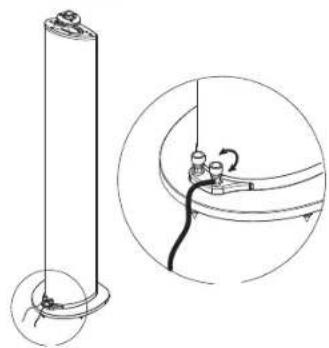
natural_image
Technical line drawing of a cylindrical component with a separate inset showing a close-up of its internal structure (no text or symbols)natural_image
Technical line drawing of a mechanical component with an inset showing a close-up view of a tool interacting with a curved tool (no text or symbols present)
natural_image
Technical line drawing of a cylindrical mechanical component with an inset close-up showing internal components (no text or symbols)
natural_image
Technical line drawing of a cylindrical component with a separate inset showing a close-up of its internal structure (no text or symbols)natural_image
Technical line drawing of a mechanical component with an inset showing a close-up of a curved tool or tool interacting with a central component (no text or symbols present)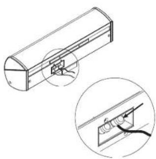
natural_image
Technical line drawing of a cylindrical mechanical component with an inset showing a magnified view of internal components (no text or symbols)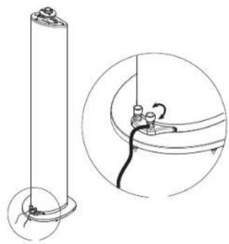
natural_image
Technical line drawing of a cylindrical component with a separate inset showing a close-up of its internal structure (no text or symbols)manuale dell'utente
STRUZIONI IMPORTANTI PER LA SICUREZZA-LEGGERE ATTENTAMENTE!
natural_image
Technical line drawing of a mechanical component with an inset showing a close-up view of a curved tool or bracket (no text or symbols present)
natural_image
Technical line drawing of a mechanical component with an inset close-up showing a detail (no text or symbols)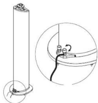
natural_image
Technical line drawing of a cylindrical component with a separate inset showing a mechanical assembly (no text or symbols)benutzerhandbuch
natural_image
Technical line drawing of a mechanical component with an inset showing a hand holding a tool (no text or symbols present)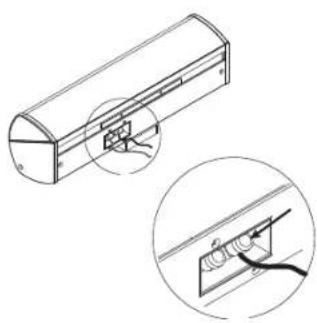
natural_image
Technical line drawing of a cylindrical mechanical component with an inset close-up showing internal components (no text or symbols)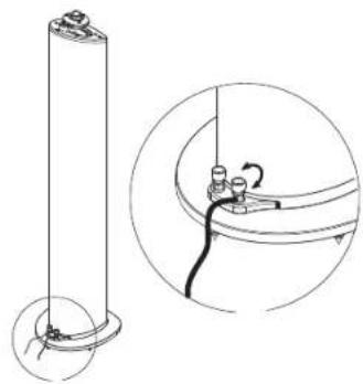
natural_image
Technical line drawing of a cylindrical component with a separate inset showing internal wiring (no text or symbols)brugerveledning
VIGTIGE OPLYSNINGER OM SIKKERHED -B∅R LÆSES OMHYGGELIGT!
natural_image
Technical line drawing of a mechanical component with an inset showing a close-up of a tool or assembly (no text or symbols present)
natural_image
Technical line drawing of a mechanical component with an inset close-up showing internal components (no text or symbols)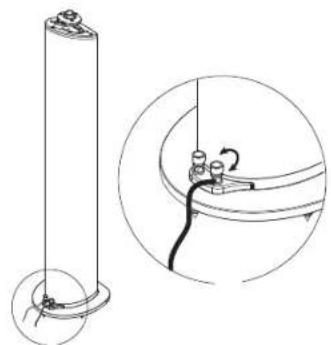
natural_image
Technical line drawing of a cylindrical component with a separate inset showing a close-up of its internal structure (no text or symbols)natural_image
Technical line drawing of a mechanical component with an inset showing a hand holding a tool (no text or symbols present)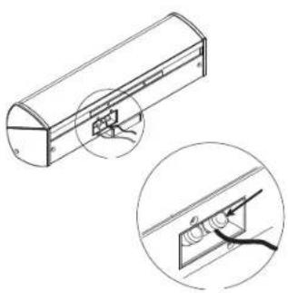
natural_image
Technical line drawing of a cylindrical mechanical component with an inset close-up showing internal components (no text or symbols)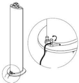
natural_image
Technical line drawing of a cylindrical component with a separate circular inset showing internal wiring (no text or symbols)natural_image
Technical line drawing of a mechanical component with an inset showing a close-up of a tool interacting with a curved tool (no text or symbols present)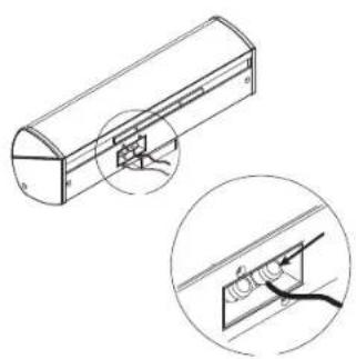
natural_image
Technical line drawing of a cylindrical mechanical component with an inset close-up showing internal components (no text or symbols)
natural_image
Technical line drawing of a cylindrical component with a separate inset showing a close-up of its internal structure (no text or symbols)natural_image
Technical line drawing of a mechanical component with an inset showing a close-up of a curved tool or bracket (no text or symbols present)
natural_image
Technical line drawing of a cylindrical device with an inset close-up showing internal components (no text or symbols)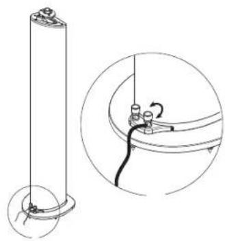
natural_image
Technical line drawing of a cylindrical component with base and mounting base, plus an inset showing a close-up of a cable or wire connection (no text or symbols)notes
diagrams
1

natural_image
Technical line drawing of a mechanical component with an inset showing a close-up view of internal components (no text or symbols)2a
Wall mount instructions
natural_image
Technical line drawing showing a hand holding a screwdriver and a mechanical bracket with fasteners (no text or symbols)
natural_image
Technical line drawing of a mechanical component with an inset close-up showing a detail (no text or symbols)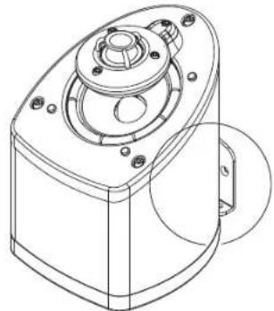
natural_image
Technical line drawing of a mechanical component with mounting holes and a central hub (no text or symbols)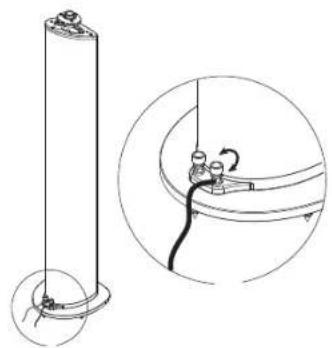
natural_image
Technical line drawing of a cylindrical component with a separate inset showing a close-up of its internal structure (no text or symbols)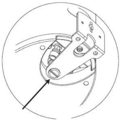
natural_image
Technical line drawing of a mechanical clamp or crimping tool inside a circular frame (no text or symbols)diagrams
2b Wall mount instructions
natural_image
Technical line drawing of a mechanical component with an inset showing a bracket detail (no text or symbols)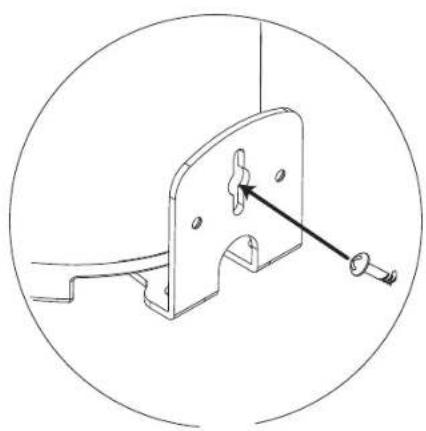
natural_image
Technical line drawing of a mechanical bracket with a pin and screw (no text or symbols)2c Ceiling mount instructions
natural_image
Line drawing of a hand holding a screwdriver inserted into a mechanical housing component (no text or symbols)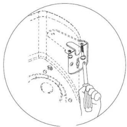
natural_image
Line drawing of a hand holding a tool inside a circular frame, with no visible text or symbolsdiagrams
3
6
natural_image
Line drawing of two hands holding a rectangular object with arrows indicating motion (no text or symbols)4
7
natural_image
Line drawing of hands installing or adjusting a device with arrows indicating movement (no text or symbols)5
8
natural_image
Line drawing of two hands holding a rectangular object with arrows indicating direction (no text or symbols)diagrams
9
natural_image
Line drawing of a hand holding a tool interacting with a mechanical component (no text or symbols)12
natural_image
Illustration of hands holding a doorbell with a close-up inset showing a hand holding a tool (no text or symbols)10
natural_image
Line drawing of a hand using a tool to adjust or install a mechanical component (no text or symbols present)13
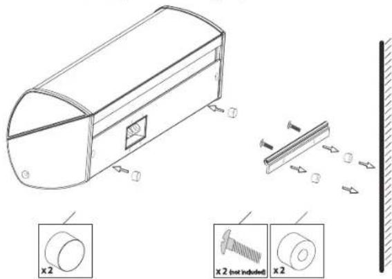
OS ^3 -CC Wall Spacer Kit Instructions: (optional)
11
natural_image
Line drawing of a hand holding a cable with a metal bracket (no text or symbols)notes
notes
WARRANTY
LIMITED WARRANTY POLICY IN THE UNITED STATES AND CANADA
MIRAGE® warrants this product to the retail purchaser against any failure resulting from original manufacturing defects in workmanship or materials. The warranty is in effect for a period of: Passive Speakers: five (5) years, Powered Subwoofers including the speaker - one (1) year from date of purchase from an authorized MIRAGE® dealer and is valid only if the original dated bill of sale is presented when service is required.
The warranty does not cover damage caused during shipment, by accident, misuse, abuse, neglect, unauthorized product modification, failure to follow the instructions outlined in the owner's manual, failure to perform routine maintenance, damage resulting from unauthorized repairs or claims based upon misrepresentations of the warranty by the seller.
WARRANTY SERVICE
If you require service for your MIRAGE® Speaker Systems speaker(s) at any time during the warranty period, please contact:
1) the dealer from whom you purchased the product(s), or
2) MIRAGE ^ Speaker Systems SERVICE – Tel: 1 (866) 441-8208.
3) Additional service centers can be found by checking the MIRAGE ^® Speaker Systems website: www.miragespeakers.com.
You will be responsible for transporting the speakers in adequate packaging to protect them from damage in transit and for the shipping costs to an authorized MIRAGE® Speaker Systems service center or to MIRAGE® Speaker Systems. If the product is returned for repair to MIRAGE® Speaker Systems the costs of the return shipment to you will be paid by MIRAGE® Speaker Systems, provided the repairs concerned fall within the Limited Warranty. The MIRAGE® Speaker Systems Warranty is limited to repair or replacement of MIRAGE® Speaker Systems products. It does not cover any incidental or consequential damage of any kind. If the provisions in any advertisement, packing cartons or literature differ from those specified in this warranty, the terms of the Limited Warranty prevail.