
MS 828 - Mixer LD Systems - Free user manual and instructions
Find the device manual for free MS 828 LD Systems in PDF.
| Product type | 8-channel Splitter/Mixer |
| Number of channels | 8 (6 mono + 1 stereo) |
| Mono line-level inputs | 6 (4 x XLR, 2 x 6.35 mm TRS balanced jacks) |
| Stereo line-level input | 1 (2 x XLR balanced) |
| Mono line-level outputs | 6 (4 x XLR, 2 x 6.35 mm TRS balanced jacks) |
| Stereo line-level output | 1 (2 x XLR balanced) |
| Input impedance | 50 kΩ (balanced), 25 kΩ (unbalanced) |
| Output impedance | 60 Ω (balanced), 30 Ω (unbalanced) |
| Maximum input level | +21 dBu |
| Maximum output level | +22 dBu |
| Frequency response | 5 Hz – 40 kHz |
| Total harmonic distortion (THD) | 0.0008% |
| Signal-to-noise ratio | 85 dB |
| Controls | Main Input/Output Level, Main Link, Level channels 1-6, Bal/Pan channels 1-6, Splitter/Mixer selectors, Ground Lift, Power |
| Indicators | Level LEDs (Main Input/Output and channels 1-6), Power LED, Main Link LED |
| Power supply | 220-240 V, 50-60 Hz, 15 W |
| Fuse | T 315 mAL, 250 V |
| Dimensions (W x H x D) | 483 x 44.5 x 216 mm |
| Weight | 3 kg |
| Maintenance and cleaning | Use a dry cloth. Disconnect the device before cleaning. |
| Safety | Do not open the device. Observe the voltage and fuse specifications. Avoid humidity and heat sources. |
| Spare parts and repairability | Repair only by qualified personnel. Fuse replaceable by user (same type and rating). |
| General information | Versatile Splitter/Mixer for live, studio or fixed installation. Modes: 2-to-8 splitter, 8-to-2 mixer, or combination. |
Frequently Asked Questions - MS 828 LD Systems
User questions about MS 828 LD Systems
0 question about this device. Answer the ones you know or ask your own.
Ask a new question about this device
Download the instructions for your Mixer in PDF format for free! Find your manual MS 828 - LD Systems and take your electronic device back in hand. On this page are published all the documents necessary for the use of your device. MS 828 by LD Systems.
USER MANUAL MS 828 LD Systems

natural_image
Exterior view of a network equipment unit (MSB28) with multiple ports and control knobs, shown against a wireframe grid background (no readable text or symbols on the device itself).8-CHANNEL SPLITTER / MIXER
LDMS828
You've made the right choice!
We have designed this product to operate reliably over many years. LD Systems stands for this with its name and many years of experience as a manufacturer of high-quality audio products.
Please read this User's Manual carefully, so that you can begin making optimum use of your LD Systems product quickly.
You can find more information about LD SYSTEMS at our Internet site WWW.LD-SYSTEMS.COM
Introduction
Thanks to its extremely variable concept, the LD Systems LDSM828 Splitter/Mixer is the solution for a very wide range of applications. All inputs and outputs are completely balanced and the clear design, e. g., level metres in each channel, supports intuitive operation. The ability to use it as an 8 in 2 mixer, a 2 in 8 splitter or a combination of both makes the LDMS828 an indispensable tool at live events, in the studio or in permanent installations.
8-CHANNEL
SPLITTER / MIXER
LDMS828

natural_image
Front view of a network switch device with multiple ports and indicator lights (no visible text or symbols)PREVENTIVE MEASURES:
- Please read these instructions carefully.
- Keep all information and instructions in a safe place.
- Follow the instructions.
- Observe all safety warnings. Never remove safety warnings or other information from the equipment.
- Use the equipment only in the intended manner and for the intended purpose.
- Use only sufficiently stable and compatible stands and/or mounts (for fixed installations). Make certain that wall mounts are properly installed and secured. Make certain that the equipment is installed securely and cannot fall down.
- During installation, observ e the applicable safety regulations for your country.
- Never install and operate the equipment near radiators, heat registers, ovens or other sources of heat. Make certain that the equipment is always installed so that is cooled sufficiently and cannot overheat.
- Never place sources of ignition, e.g., burning candles, on the equipment.
- Ventilation slits must not be blocked.
- Do not use this equipment in the immediate vicinity of water (does not apply to special outdoor equipment - in this case, observe the special instructions noted below. Do not expose this equipment to flammable materials, fluids or gases.
- Make certain that dripping or splashed water cannot enter the equipment. Do not place containers filled with liquids, such as vases or drinking vessels, on the equipment.
- Make certain that objects cannot fall into the device.
- Use this equipment only with the accessories recommended and intended by the manufacturer.
- Do not open or modify this equipment.
- After connecting the equipment, check all cables in order to prevent damage or accidents, e.g., due to tripping hazards.
- During transport, make certain that the equipment cannot fall down and possibly cause property damage and personal injuries.
- If your equipment is no longer functioning properly, if fluids or objects have gotten inside the equipment or if it has been damaged in anot her way, switch it off immediately and unplug it from the mains outlet (if it is a powered device). This equipment may only be repaired by authorized, qualified personnel.
- Clean the equipment using a dry cloth.
- Comply with all applicable disposal laws in your country. During disposal of packaging, please separate plastic and paper/cardboard.
- Plastic bags must be kept out of reach of children.
FOR EQUIPMENT THAT CONNECTS TO THE POWER MAINS:
-
CAUTION: If the power cord of the device is equipped with an earthing contact, then it must be connected to an outlet with a protective ground. Never deactivate the protective ground of a power cord.
-
If the equipment has been exposed to strong fluctuations in temperature (for example, after transport), do not switch it on immediately. Moisture and condensation could damage the equipment. Do not switch on the equipment until it has reached room temperature.
-
Before connecting the equipment to the power outlet, first verify that the mains voltage and frequency match the values specified on the equipment. If the equipment has a voltage selection switch, connect the equipment to the power outlet only if the equipment values and the mains power values match. If the included power cord or power adapter does not fit in your wall outlet, contact your electrician.
-
Do not step on the power cord. Make certain that the power cable does not become kinked, especially at the mains outlet and/or power adapter and the equipment connector.
-
When connecting the equipment, make certain that the power cord or power adapter is always freely accessible. Always disconnect the equipment from the power supply if the equipment is not in use or if you want
SAFETY:
to clean the equipment. Always unplug the power cord and power adapter from the power outlet at the plug or adapter and not by pulling on the cord. Never touch the power cord and power adapter with wet hands.
-
Whenever possible, avoid switching the equipment on and off in quick succession because otherwise this can shorten the useful life of the equipment.
-
IMPORTANT INFORMATION: Replace fuses only with fuses of the same type and rating. If a fuse blows repeatedly, please contact an authorised service centre.
-
To disconnect the equipment from the power mains completely, unplug the power cord or power adapter from the power outlet.
-
If your device is equipped with a Volex power connector, the mating Volex equipment connector must be unlocked before it can be removed. However, this also means that the equipment can slide and fall down if the power cable is pulled, which can lead to personal injuries and/or other damage. For this reason, always be careful when laying cables.
-
Unplug the power cord and power adapter from the power outlet if there is a risk of a lightning strike or before extended periods of disuse.

CAUTION:
Never remove the cover, because otherwise there may be a risk of electric shock. There are no user serviceable parts inside. Have repairs carried out only by qualified service personnel.

The lightning flash with arrowhead symbol within an equilateral triangle is intended to alert the user to the presence of uninsulated “dangerous voltage” within the product’s enclosure that may be of sufficient magnitude to constitute a risk of electrical shock.

The exclamation mark within an equilateral triangle is intended to alert the user to the presence of important operating and maintenance instructions.
CAUTION – HIGH VOLUME LEVELS WITH AUDIO PRODUCTS!
This equipment is intended for professional use. Therefore, commercial use of this equipment is subject to the respectively applicable national accident prevention rules and regulations. As a manufacturer, Adam Hall is obligated to notify you formally about the existence of potential health risks.
Hearing damage due to high volume and prolonged exposure: When in use, this product is capable of producing high sound-pressure levels (SPL) that can lead to irreversible hearing damage in performers, employees, and audience members. For this reason, avoid prolonged exposure to volumes in excess of 90 dB.
CAUTION! IMPORTANT INFORMATION ABOUT LIGHTING PRODUCTS
- Do not look into the beam from a distance of less than 40 cm.
- Do not stare into the beam for extended periods at short-to-medium distances.
- Do not view the beam directly with optical instruments such as magnifiers.
- Under some circumstances, stroboscopic effects may trigger epileptic seizures in sensitive individuals! For this reason, persons who suffer from epilepsy should always avoid places where strobe lights are used.
CONTROLS AND INDICATORS:

① SPLITTER / MAIN INPUT LEVEL
Volume control for the signal at the stereo input (MAIN IN LEFT/RIGHT).
Volume control for the signal at the stereo output (MAIN OUT LEFT/RIGHT).
3 MAIN LINK
When the MAIN LINK switch is depressed, the signal at the stereo input (MAIN IN LEFT/RIGHT) is sent to the stereo output (MAIN OUT LEFT/RIGHT). The result is a mix of signals from the stereo output and mixer channels 1 - 6, which are connected as mixer channels (Button 8 in channel depressed).
4 INPUT LEVEL
6-segment LED level metre for the signal at the stereo input (MAIN IN LEFT/RIGHT). The red CLIP LED of the level metre lights up as soon as the level of the signal at the stereo input is 4 dB below the clipping threshold. Brief flashing of the CLIP LED when peaks occur in the connected signal is not critical. Permanent illumination of the CLIP LED should be avoided by reducing the volume of the source device and/or the volume at the MAIN INPUT LEVEL control.
5 OUTPUT LEVEL
6-segment LED level metre for the signal at the stereo output (MAIN OUT LEFT/RIGHT). The red CLIP LED of the level metre lights up as soon as the level of the signal at the stereo output reaches the clipping threshold. Brief flashing of the CLIP LED when peaks occur in the connected signal is not critical. Permanent illumination of the CLIP LED should be avoided by reducing the volume of the source device, channels 1 - 6, and/or the volume at the MAIN INPUT LEVEL control.
6 LEVEL CH1 - CH6
Channel in SPLITTER mode: Volume control for the signals at the stereo input. The signals are sent to the individual output of the respective channel (OUTPUT CHANNEL 1 - 6). The signal strength also depends on the MAIN INPUT LEVEL volume control.
Channel in MIXER mode: Volume control for the signal at the individual input channel 1 - 6. The signal is switched to the stereo output (MAIN OUT LEFT/RIGHT).
CONTROLS AND INDICATORS:

Channel in SPLITTER mode: Balance control for the signals at the stereo input. Adjustment of the balance in volume between the left and right input signal (MAIN IN). The two signals are merged into a mono signal that is present at the output of each channel.
Channel in MIXER mode: Panorama control for the signal at the individual input channel 1 - 6. Setting of the position in the stereo mix of the MAIN OUT.
8 SPLITTER- / MIXER
Switch not depressed: Respective channel 1 - 6 is used as a splitter channel.
Signal flow: MAIN IN LEFT/RIGHT (12) → MAIN INPUT LEVEL (1) → CHANNEL LEVEL (6) → CHANNEL OUTPUT (15)
Switch depressed: Respective channel 1 - 6 is used as a mixer channel.
Signal flow: CHANNEL INPUT (14) CHANNEL LEVEL (6) MAIN OUTPUT LEVEL (2) MAIN OUT LEFT/RIGHT (13)
9 IN / OUT LEVEL
Channel in SPLITTER mode: 6-segment LED level meter for the output level of the respective channel 1 - 6. Brief flashing of the red CLIP LED when peaks occur in the connected signal is not critical. Permanent illumination of the CLIP LED should be avoided by reducing the volume at the MAIN INPUT LEVEL control and or at the LEVEL control in the channel.
Channel in MIXER mode: 6-segment LED level meter for the input level of the respective channel 1 - 6. Brief flashing of the red CLIP LED when peaks occur in the connected signal is not critical. Permanent illumination of the CLIP LED should be avoided by reducing the volume of the source device and/or the volume at the LEVEL control in the channel.
10 POWER
On / off switch
11 POWER LED
Lights up once the system is properly connected to the power mains and switched on.
CONNECTIONS:

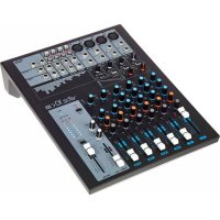
12 MAIN IN LEFT/RIGHT
Balanced XLR stereo input left and right.
13 MAIN OUT LEFT/RIGHT
Balanced XLR stereo output left and right.
14 INPUT CHANNEL 1 - 6
Balanced line inputs. Channels 1 - 4 have female XLR sockets; channels 5 and 6 have 6.3 mm stereo TRS sockets. In order to make a connection with the TRS inputs, unbalanced cables with mono jack (TRS) plugs can also be used. However, the balanced connection is preferable to the non-balanced connection.
15 OUTPUT CHANNEL 1 - 6
Balanced line outputs. Channels 1 - 4 have male XLR sockets; channels 5 and 6 have 6.3 mm stereo TRS sockets. In order to make a connection with the TRS outputs, unbalanced cables with mono jack (TRS) plugs can also be used. However, the balanced connection is preferable to the non-balanced connection.
16 GROUND LIFT
Switch in "Lift" position (right switch position) can prevent ground loop hum if devices with varying ground potential are connected. If the switch is in "Ground" position (left switch position), then the ground lift function is deactivated.
⑰ IEC POWER SOCKET WITH INTEGRAL FUSE HOLDER
IMPORTANT INFORMATION: Make certain BEFORE turning on the equipment that the mains voltage of your energy supplier and the operating voltage of the device match! Always replace the fuse only with a fuse of the same type with the same rating (printed on the rear panel)! If the fuse blows repeatedly, please contact an authorised service centre.
CONNECTIONS.

APPLICATION EXAMPLES:

■ SPLITTER
■ MIXER
SPUTTER/MIXER switch channels 1 - 6 in
USE AS A 6 IN 6 BOOSTER AMPULIFER
APPLICATION EXAMPLES:
USE AS A 2 IN 8 SPLITTER


APPLICATION EXAMPLES:
NOTE: A combination of splitter and mixer modes is also possible.
Amplifier Stereo signal
Line Signal 6 Line Signal 5 Line Signal 4 Line Signal 3 Line Signal 2 Line Signal 1


■ SPUFTER
—— MIXER

USE AS AN 8 IN 2 MIXER
MAIN LINK switch depressed
SPUTTER/MIXER switch channels 1 - 6 in
depressed MIXER position

SCHEMATIC DIAGRAM:

flowchart
graph TD
    subgraph MAIN_LEFT_MAIN_LEFT
        A1["4"] --> B1["△"]
        A2["3"] --> B2["△"]
        A3["4"] --> B3["△"]
        A4["3"] --> B4["△"]
        A5["4"] --> B5["△"]
        A6["3"] --> B6["△"]
        A7["4"] --> B7["△"]
        A8["3"] --> B8["△"]
        A9["4"] --> B9["△"]
        A10["4"] --> B10["△"]
        A11["3"] --> B11["△"]
        A12["4"] --> B12["△"]
        A13["3"] --> B13["△"]
        A14["4"] --> B14["△"]
        A15["3"] --> B15["△"]
        A16["4"] --> B16["△"]
        A17["3"] --> B17["△"]
        A18["4"] --> B18["△"]
        A19["3"] --> B19["△"]
        A20["4"] --> B20["△"]
        A21["3"] --> B21["△"]
        A22["4"] --> B22["△"]
        A23["3"] --> B23["△"]
        A24["4"] --> B24["△"]
        A25["3"] --> B25["△"]
        A26["4"] --> B26["△"]
        A27["3"] --> B27["△"]
        A28["4"] --> B28["△"]
        A29["3"] --> B29["△"]
        A30["4"] --> B30["△"]
        A31["3"] --> B31["△"]
        A32["4"] --> B32["△"]
        A33["3"] --> B33["△"]
        A34["4"] --> B34["△"]
        A35["3"] --> B35["△"]
        A36["4"] --> B36["△"]
        A37["3"] --> B37["△"]
        A38["4"] --> B38["△"]
        A39["3"] --> B39["△"]
        A40["4"] --> B40["△"]
        A41["3"] --> B41["△"]
        A42["4"] --> B42["△"]
        A43["3"] --> B43["△"]
        A44["4"] --> B44["△"]
        A45["3"] --> B45["△"]
        A46["4"] --> B46["△"]
        A47["3"] --> B47["△"]
        A48["4"] --> B48["△"]
        A49["3"] --> B49["△"]
        A50["4"] --> B50["△"]
        A51["3"] --> B51["△"]
        A52["4"] --> B52["△"]
        A53["3"] --> B53["△"]
        A54["4"] --> B54["△"]
        A55["3"] --> B55["△"]
        A56["4"] --> B56["△"]
        A57["3"] --> B57["△"]
        A58["4"] --> B58["△"]
        A59["3"] --> B59["△"]
        A60["4"] --> B60["△"]
        A61["3"] --> B61["△"]
        A62["4"] --> B62["△"]
        A63["3"] --> B63["△"]
        A64["4"] --> B64["△"]
        A65["3"] --> B65["△"]
        A66["4"] --> B66["△"]
        A67["3"] --> B67["△"]
        A68["4"] --> B68["△"]
        A69["3"] --> B69["△"]
        A70["4"] --> B70["△"]
        A71["3"] --> B71["△"]
        A72["4"] --> B72["△"]
        A73["3"] --> B73["△"]
        A74["4"] --> B74["△"]
        A75["3"] --> B75["△"]
        A76["4"] --> B76["△"]
        A77["3"] --> B77["△"]
        A78["4"] --> B78["△"]
    end
    subgraph MAIN_RIGHT_MAIN_RIGHT
        A8(4) --> B8(Δ)
        A9(3) --> B9(Δ)
    end
    subgraph CH1
            CH1_1
            CH1_2
            CH1_3
            CH1_4
            CH1_5
            CH1_6
            CH1_7
            CH1_8
            CH1_9
            CH1_10
            CH1_11
            CH1_12
            CH1_13
            CH1_14
            CH1_15
            CH1_16
            CH1_17
            CH1_18
            CH1_19
            CH1_20
            CH1_21
            CH1_22
            CH1_23
            CH1_24
            CH1_25
            CH1_26
            CH1_27
            CH1_28
            CH1_29
            CH1_30
            CH1_31
            CH1_32
            CH1_33
            CH1_34
            CH1_35
            CH1_36
            CH1_37
            CH1_38
            CH1_39
            CH1_40
            CH1_41
            CH1_42
            CH1_43
            CH1_44
            CH1_45
            CH1_46
            CH1_47
            CH1_48
            CH1_49
            CH1_50
            CH1_51
            CH1_52
            CH1_53
            CH1_54
            CH1_55
            CH1_56
            CH1_57
            CH1_58
            CH1_59
            CH1_60
            CH1_61
            CH1_62
            CH1_63
            CH1_64
            CH1_65
            CH1_66
            CH1_67
            CH1_68
            CH1_69
            CH1_70
            CH1_71
            CH1_72
            CH1_73
            CH1_74
            CH1_75
            CH1_76
            CH1_77
            CH1_78
            CH1_79
            CH1_80
            CH1_81
            CH1_82
            CH1_83
            CH1_84
            CH1_85
            CH1_86
            CH1_87
            CH1_88
            CH1_89
            CH1_90
            CH1_91
            CH1_92
            CH1_93
            CH1_94
            CH1_95
            CH1_96
            CH1_97
            CH1_98
            CH1_99
            CH20
            CH20_A
          ↓   ↓   ↓   ↓   ↓   ↓   ↓   ↓   ↓   ↓   ↓   ↓   ↓   ↓   ↓   ↓   ↓   ↓   ↓   ↓   ↓   ↓   ↓   ↓   ↓   ↓   ↓   ↓   ↓   ↓   ↓   ↓   ↓   ↓   ↓   ↓   ↓   ↓   ↓   ↓   ↓   ↓   ↓   ↓   ↓   ↓   ↓   ↓   ↓   ↓   ↓  ↓  ↓  ↓  ↓  ↓  ↓  ↓  ↓  ↓  ↓  ↓  ↓  ↓  ↓  ↓  ↓  ↓  ↓  ↓  ↓  ↓  ↓  ↓  ↓  ↓  ↓  ↓  ↓  ↓  ↓  ↓  ↓  ↓  ↓  ↓  ↓  ↓  ↓  ↓  ↓  ↓  ↓  ↓  ↓  ↓  ↓  ↑  ↑  ↑  ↑  ↑  ↑  ↑  ↑  ↑  ↑  ↑  ↑  ↑  ↑  ↑  ↑  ↑  ↑  ↑  ↑  ↑  ↑  ↑  ↑  ↑  ↑  ↑  ↑  ↑  ↑  ↑  ↑  ↑  ↑  ↑  ↑  ↑  ↑  ↑  ↑  ↑  ↑  ↑  ↑  ↑  ↑  ↑  ↑  ↑  ↑  →      |
    end
SPECIFICATIONS:
| Model name: LDMS828 | |
| Product type: splitter / mixer | |
| Type: live, installation | |
| Channels: 8 | |
| Mono input channels, line: 6 | |
| Stereo line input connectors: 4x XLR, 2x 6.3 mm jack | |
| Mono line input type: electronically balanced | |
| Stereo input channels, line: 1 | |
| Stereo line input connectors: 2 x XLR | |
| Stereo line input type: electronically balanced | |
| Input impedance: 50000 ohms (balanced), 25000 ohms (unbalanced) | |
| Maximum input level: + 21 dBu | |
| Nominal working level: -10 dBV to +4 dBu | |
| Mono output channels: 6 | |
| Mono output connectors: 4x XLR, 2x 6.3 mm jack | |
| Mono output type: electronically balanced | |
| Stereo output channels: 1 | |
| Stereo output connectors: | 2x XLR |
| Stereo output type: | electronically balanced |
| Output impedance: | 60 ohms (balanced), 30 ohms (unbalanced) |
| Maximum output level: + 22 dBu | |
| Frequency response: | 5 Hz - 40,000 Hz |
| THD: | 0,0008 % |
| S/N ratio: | 85 dB |
| Controls: | Main Input Level, Main Output Level, Main Link, Level Channel 1-6, Bal/Pan Channel 1-6, Splitter/Mixer Channel 1-6, Power, Ground Lift |
SPECIFICATIONS:
| Indicators: Input Level LED Indicator (6-segment), Output LevelIndicator (6-segment), In/Out Level Channel 1-6(6 -segment), Power |
| Operating voltage: 220 - 240 V AC, 50 - 60 Hz |
| Power socket: IEC power socket |
| Power consumption: 15 W |
| Fuse: T 315 mAL, AC 250V |
| Dimensions (W x H x D): 483 x 44.5 x 216 mm |
| Weight: 3 kg |
| Included accessories: User manual, power cord |
MANUFACTURER'S DECLARATIONS:
MANUFACTURER'S WARRANTY
This warranty covers the Adam Hall, LD Systems, Defender, Palmer, and Cameo brands.
It applies to all products distributed by Adam Hall.
This warranty declaration does not affect the statutory warranty claims against the manufacturer, but expands them with additional warranty claims vis-a-vis Adam Hall.
Adam Hall warrants that the Adam Hall product that you have purchased from Adam Hall or from an Adam Hall authorized reseller is free from defects in materials or workmanship under normal use for a period of 2 or 5 years (please inquire on a product-by-product basis) from the date of purchase.
The warranty period begins on the date on which the product was purchased, proof of which must be produced (through presentation of the invoice or the delivery note with the date of purchase) in the event of a warranty claim. Should products of the brands named above be in need of repair within the limited warranty period, you are entitled to warranty service according to the terms and conditions stated here.
During the Limited Warranty Period, Adam Hall will repair or replace the defective component parts or the product. In the event of repair or replacement during the Limited Warranty Period, the replaced original parts and/or products become property of Adam Hall.
In the unlikely event that the product which you purchased has a recurring failure, Adam Hall has the right, at its discretion, to replace the defective product with another product, provided that the new product is at least equivalent to the product being replaced with regard to the technical specifications.
Adam Hall does not warrant that the operation of this product will be uninterrupted or error-free. Adam Hall is not responsible for damage that occurs as a result of your failure to follow the instructions included with the Adam Hall branded product. The manufacturer's warranty does not cover – expendable parts (e.g., rechargeable batteries) - products from which the serial number has been removed or with a serial number that has been damaged as a result of an accident - damage due to improper use, user error or other external reasons - damage to devices operated outside the usage parameters stated in the documentation included with the product - damage due to the use of replacement parts not manufactured, sold or recommended by Adam Hall, - damage due to modification or servicing by anyone other than Adam Hall.
These terms and conditions constitute the complete and exclusive warranty agreement between you and Adam Hall regarding the Adam Hall branded product you have purchased.
MANUFACTURER'S DECLARATIONS:
LIMITATION OF LIABILITY
If your Adam Hall branded hardware product fails to work as warranted above, your sole and exclusive remedy shall be repair or replacement. Adam Halls' maximum liability under this limited warranty is expressly limited to the lesser of the price you have paid for the product or the cost of repair or replacement of any components that malfunction under conditions of normal use.
Adam Hall is not liable for any damages caused by the product or the failure of the product, including any lost profits or savings or special, incidental, or consequential damages. Adam Hall is not liable for any claim made by a third party or made by you for a third party.
This limitation of liability applies whether damages are sought, or claims are made, under this Limited Warranty or as a tort claim (including negligence and strict product liability), a contract claim, or any other claim, and cannot be rescinded or changed by anyone. This limitation of liability will be effective even if you have advised Adam Hall or an authorized representative of Adam Hall of the possibility of any such damages, but not, however, in the event of claims for damages in connection with personal injuries.
This manufacturer's warranty grants you specific rights; depending on jurisdiction (nation or state), you may be entitled to additional claims. You are advised to consult applicable state or national laws for a full determination of your rights.
REQUESTING WARRANTY SERVICE
To request warranty service for the product, contact Adam Hall or the Adam Hall authorized reseller from which you purchased the product.
EC DECLARATION OF CONFORMITY
The equipment marketed by Adam Hall complies (where applicable) with the essential requirements and other relevant specifications of Directives 1999/5/EC (R&TTE), 2004/108/EC (EMC) und 2006/95/EC (LVD). Additional information can be found at www.adamhall.com.
MANUFACTURER'S DECLARATIONS:
PROPER DISPOSAL OF THIS PRODUCT
(Valid in the European Union and other European countries with waste separation)

This symbol on the product, or the documents accompanying the product, indicates that this appliance may not be treated as household waste. This is to avoid environmental damage or personal injury due to uncontrolled waste disposal. Please dispose of this product separately from other waste and have it recycled to promote sustainable economic activity.
Household users should contact either the retailer where they purchased this product, or their local government office, for details on where and how they can recycle this item in an environmentally friendly manner. Business users should contact their supplier and check the terms and conditions of the purchase contract. This product should not be mixed with other commercial wastes for disposal.
ENVIRONMENTAL PROTECTION AND ENERGY CONSERVATION
Energy conservation is an active contribution to environmental protection. Please turn off all unneeded electrical devices. To prevent unneeded devices from consuming power in standby mode, disconnect the mains plug.
Adam Hall GmbH, all rights reserved. The technical data and the functional product characteristics can be subject to modifications. The photocopying, the translation, and all other forms of copying of fragments or of the integrity of this user's manual is prohibited.
natural_image
Front view of a network switch device with multiple ports and indicator lights (no visible text or symbols)12 MAIN IN LEFT/RIGHT
■ SPLITTER ■ MIXER
flowchart
graph TD
    subgraph Main_LEFT_MAIN_LEFT
        A1["4"] --> B1["Δ"]
        A2["3"] --> B2["Δ"]
        A3["4"] --> B3["Δ"]
        A4["3"] --> B4["Δ"]
        A5["4"] --> B5["Δ"]
        A6["3"] --> B6["Δ"]
        A7["4"] --> B7["Δ"]
        A8["3"] --> B8["Δ"]
        A9["4"] --> B9["Δ"]
        A10["3"] --> B10["Δ"]
        A11["4"] --> B11["Δ"]
        A12["3"] --> B12["Δ"]
        A13["4"] --> B13["Δ"]
        A14["3"] --> B14["Δ"]
        A15["4"] --> B15["Δ"]
        A16["3"] --> B16["Δ"]
        A17["4"] --> B17["Δ"]
        A18["3"] --> B18["Δ"]
        A19["4"] --> B19["Δ"]
        A20["3"] --> B20["Δ"]
        A21["4"] --> B21["Δ"]
        A22["3"] --> B22["Δ"]
        A23["4"] --> B23["Δ"]
        A24["3"] --> B24["Δ"]
        A25["4"] --> B25["Δ"]
        A26["3"] --> B26["Δ"]
        A27["4"] --> B27["Δ"]
        A28["3"] --> B28["Δ"]
        A29["4"] --> B29["Δ"]
        A30["3"] --> B30["Δ"]
        A31["4"] --> B31["Δ"]
        A32["3"] --> B32["Δ"]
        A33["4"] --> B33["Δ"]
        A34["3"] --> B34["Δ"]
        A35["4"] --> B35["Δ"]
        A36["3"] --> B36["Δ"]
        A37["4"] --> B37["Δ"]
        A38["3"] --> B38["Δ"]
        A39["4"] --> B39["Δ"]
        A40["3"] --> B40["Δ"]
        A41["4"] --> B41["Δ"]
        A42["3"] --> B42["Δ"]
        A43["4"] --> B43["Δ"]
        A44["3"] --> B44["Δ"]
        A45["4"] --> B45["Δ"]
        A46["3"] --> B46["Δ"]
        A47["4"] --> B47["Δ"]
        A48["3"] --> B48["Δ"]
        A49["4"] --> B49["Δ"]
        A50["3"] --> B50["Δ"]
        A51["4"] --> B51["Δ"]
        A52["3"] --> B52["Δ"]
        A53["4"] --> B53["Δ"]
        A54["3"] --> B54["Δ"]
        A55["4"] --> B55["Δ"]
        A56["3"] --> B56["Δ"]
        A57["4"] --> B57["Δ"]
        A58["3"] --> B58["Δ"]
        A59["4"] --> B59["Δ"]
        A60["3"] --> B60["Δ"]
        A61["4"] --> B61["Δ"]
        A62["3"] --> B62["Δ"]
        A63["4"] --> B63["Δ"]
        A64["3"] --> B64["Δ"]
        A65["4"] --> B65["Δ"]
        A66["3"] --> B66["Δ"]
        A67["4"] --> B67["Δ"]
        A68["3"] --> B68["Δ"]
        A69["4"] --> B69["Δ"]
    end

    subgraph Balance
        C1[SPLIT/MIX 1,2,3,4,5,6,7,8,9,10,11,12,13,14,15,16,17,18,19,20,21,22,23,24,25,26,27,28,29,30,31,32,33,34,35,36,37,38,39,40,41,42,43,44,45,46,47,48,49,50,51,52,53,54,55,56,57,58,59,60,61,62,63,64,65,66,67,68,69,70,71,72,73,74,75,76,77,78,79,80,81,82,83,84,85,86,87,88,89,90,91,92,93,94,95,96,97,98,99
    end

    subgraph SPLIT/MIX
        T[SPLIT/MIX 1,2,3,4,5,6,7,8,9,10,11,12,13,14,15,16,17,18,19,20,21,22,23,24,25,26,27,28,29,30,31,32,33,34,36,37,38,39,40,41,42,43,44,45,46,47,48,49
    end

    subgraph LEVEL
        U[SPLIT/MIX 1,SPLIT/MIX 2,SPLIT/MIX 3,SPLIT/MIX 4,SPLIT/MIX 5,SPLIT/MIX 6,SPLIT/MIX 7,SPLIT/MIX 8,SPLIT/MIX 9,SPLIT/MIX 10,SPLIT/MIX 11,SPLIT/MIX 12,SPLIT/MIX 13,SPLIT/MIX 14,SPLIT/MIX 15,SPLIT/MIX 16,SPLIT/MIX 17,SPLIT/MIX 18,SPLIT/MIX 19,SPLIT/MIX 20,SPLIT/MIX 21,SPLIT/MIX 22,SPLIT/MIX 23,SPLIT/MIX 24,SPLIT/MIX 25,SPLIT/MIX 26,SPLIT/MIX 27,SPLIT/MIX 28,SPLIT/MIX 29,SPLIT/MIX 30,SPLIT/MIX 31,SPLIT/MIX 32,SPLIT/MIX 33,SPLIT/MIX 34,SPLIT/MIX 35,SPLIT/MIX 36,SPLIT/MIX 37,SPLIT/MIX 38,SPLIT/MIX 39,SPLIT/MIX 40,SPLIT/MIX 41,SPLIT/MIX 42,SPLIT/MIX 43,SPLIT/MIX 44,SPLIT/MIX 45,SPLIT/MIX 46,SPLIT/MIX 47,SPLIT/MIX 48,SPLIT/MIX 49,SPLIT/MIX 50,SPLIT/MIX 51,SPLIT/MIX 52,SPLIT/MIX 53,SPLIT/MIX 54,SPLIT/MIX 55,SPLIT/MIX 56,SPLIT/MIX 57,SPLIT/MIX 58,SPLIT/MIX 59,SPLIT/MIX 60,SPLIT/MIX 61,SPLIT/MIX 62,SPLIT/MIX 63,SPLIT/MIX 64,SPLIT/MIX 65,SPLIT/MIX 66,SPLIT/MIX 67,SPLIT/MIX 68,SPLIT/MIX 69,SPLIT/MIX 70,SPLIT/MIX 71,SPLIT/MIX 72,SPLIT/MIX 73,SPLIT/MIX 74,SPLIT/MIX 75,SPLIT/MIX 76,SPLIT/MIX 77,SPLIT/MIX 78,SPLIT/MIX 79,SPLIT/MIX 80,SPLIT/MIX 81,SPLIT/MIX 82,SPLIT/MIX 83,SPLIT/MIX 84,SPLIT/MIX 85,SPLIT/MIX 86,SPLIT/MIX 87,SPLIT/MIX 88,SPLIT/MIX 89,SPLIT/MIX 90,SPLIT/MIX 91,SPLIT/MIX 92,SPLIT/MIX 93,SPLIT/MIX 94,SPLIT/MIX 95,SPLIT/MIX 96,SPLIT/MIX 97,SPLIT/MIX 98,SPLIT/MIX 99,SPLIT/MIX
    end

    subgraph LEVEL
        U[SplitMIX 1-SplitMIX 2-SplitMIX 3-SplitMIX 4-SplitMIX 5-SplitMIX 6-SplitMIX 7-SplitMIX 8-SplitMIX 9-SplitMIX
    end

    subgraph Split_Mix
        U[SplitMIX 1-SplitMIX 2-SplitMIX 3-SplitMIX 4-SplitMIX 5-SplitMIX
    end

    subgraph Split_Mix
        U[SplitMIX 1-SplitMIX 2-SplitMIX 3-SplitMIX
    end

    subgraph Split_Mix
        U[SplitMIX 1-SplitMIX 2-SplitMIX
    end

    subgraph Split_Mix
        U[SplitMIX 1-SplitMIX 2-SplitMIX
    end

    subgraph Split_Mix
        U[SplitMIX 1-SplitMIX 2-SplitMIX
    end

    subgraph Split_Mix
        U[SplitMIX 1-SplitMIX
    end

    subgraph Split_Mix
        U[SplitMIX 1-SplitMIX
    end

    subgraph Split_Mix
        U[SplitMIX 1-SplitMIX
    end

    subgraph Split_Mix
        U[SplitMIX 1-SplitMIX
    end

    subgraph Split_Mix
        U[SplitMIX 1-SplitMIX
    end
    subgraph Split_Mix
        U[SplitMIX 1-SplitMIX
    end

    subgraph Split_Mix
        U[SplitMIX 1-SplitMIX
    end

    subgraph Split_Mix
        U[SplitMIX 1-SplitMIX
    end

    subgraph Split_Mix
        U[SplitMIX 1-SplitMIX
    end

    subgraph Split_Mix
       U[SplitMIX 1-SplitMIX
    end

    subgraph Split_Mix
       U[SplitMIX 1-SplitMIX
    end

    subgraph Split_Mix
       U[SplitMIX 1-SplitMIX
    end

    subgraph Split_Mix
       U[SplitMIX 1-SplitMIX
    end

    subgraph Split_Mix
       U[SplitMIX 1-Shelfing/Resistance/Resistance/Resistance/Resistance/Resistance/Resistance/Resistance/Resistance/Resistance/Resistance/Resistance/Resistance/Resistance/Resistance/Resistance/Resistance/Resistance/Resistance/Resistance/Resistance/Resistance/Resistance/Resistance/Resistance/Resistance/Resistance/Resistance/Resistance/Resistance/Resistance/Resistance/Resistance/Resistance/Resistance/Resistance/Resistance/Resistance/Resistance/Resistance/Resistance/Resistance/Resistance/Resistance/Resistance/Resistance/Resistance/Resistance/Resistance/Resistance/Resistance/Reversals
      end

    subgraph Breakdowns
       Z[SplitMIX=0.0Sine Gain=0.0Vdcance=0.0Vdcance=0.0Vdcance=0.0Vdcance=0.0Vdcance=0.0Vdcance=0.0Vdcance=0.0Vdcance=0.0Vdcance=0.0Vdcance=0.0Vdcance=0.0Vdcance=0.0Vdcance=0.0Vdcance=0.0Vdcance=Nonlinearity: Nonlinearity = Nonlinearity = Nonlinearity = Nonlinearity = Nonlinearity = Nonlinearity = Nonlinearity = Nonlinearity = Nonlinearity = Nonlinearity = Nonlinearity = Nonlinearity = Nonlinearity = Nonlinearity = Nonlinearity = Nonlinearity = Nonlinearity = Nonlinearity = Nonlinearity = Nonlinearity = Nonlinearity = Nonlinearity = Nonlinearity = Nonlinearity = Nonlinearity = Nonlinearity=Nonlinearity = Nonlinearity=Nonlinearity=Nonlinearity=Nonlinearity=Nonlinearity=Nonlinearity=Nonlinearity=Nonlinearity=Nonlinearity=Nonlinearity=Nonlinearity=Nonlinearity=Nonlinearity=Nonlinearity=Nonlinearity=Nonlinearity=Nonlinearity=Nonlinearity=Nonlinearity=Nonlinearity=Nonlinearity=Nonlinearity=Nonlinearity=Nonlinearity=Nonlinearity=Nonlinearity=Normal Linearity = Normal Linearity = Normal Linearity = Normal Linearity = Normal Linearity = Normal Linearity = Normal Linearity = Normal Linearity = Normal Linearity = Normal Linearity = Normal Linearity = Normal Linearity = Normal Linearity = Normal Linearity = Normal Linearity = Normal Linearity = Normal Linearity = Normal Linearity = Normal Linearity = Normal Linearity = Normal Linearity = Normal Linearity = Normal Linearity = Normal Linearity = Normal Linearity = Normal Linearity = Nonlinearity = Nonlinearity = Nonlinearity = Nonlinearity = Nonlinearity = Nonlinearity = Nonlinearity = Nonlinearity = Nonlinearity = Nonlinearity = Nonlinearity = Nonlinearity = Nonlinearity = Nonlinearity = Nonlinearity = Nonlinearity = Nonlinearity = Nonlinearity = Nonlinearity = Nonlinearity = Nonlinearity = Nonlinearity = Nonlinearity = Nonlinearity = NonLinearity = NonLinearity = NonLinearity = NonLinearity = NonLinearity = NonLinearity = NonLinearity = NonLinearity = NonLinearity = NonLinearity = NonLinearity = NonLinearity = NonLinearity = NonLinearity = NonLinearity = NonLinearity = NonLinearity = NonLinearity = NonLinearity = NonLinearity = NonLinearity = NonLinearity = NonLinearity = NonLinearity = NonLinearity = Nonlinearity = Nonlinearity = Nonlinearity = Nonlinearity = Nonlinearity = Nonlinearity = Nonlinearity = Nonlinearity = Nonlinearity = Nonlinearity = Nonlinearity = Nonlinearity = Nonlinearity = Nonlinearity = Nonlinearity = Nonlinearity = Nonlinearity = Nonlinearity = Nonlinearity = Nonlinearity = Nonlinearity = Nonlinearity = Nonlinearity = Nonlinearity = Nonlinearly Average Value (Average Value) for each line type.
    end
SPEZIFIKATIONEN:
natural_image
Front view of a network switch device with multiple ports and indicator lights (no visible text or symbols on the device body)12 MAIN IN LEFT/RIGHT


SPULLER
MIXER
DÉCLARATION DE CONFORMITÉ CE
MISE AU REBUT DE CE PRODUIT
natural_image
Front view of a network switch device with multiple ports and indicator lights (no visible text or labels)12 MAIN IN LEFT/RIGHT
14 INPUT CHANNEL (1 a 6)
Commander MAIN LINK pulsado
natural_image
Front view of a network switch device with multiple ports and indicator lights (no visible text or labels)ŚRODKI OSTROŻNOŚCI:

12 MAIN IN LEFT/RIGHT
14 INPUT CHANNEL 1-6
GWARANCJA PRODUCENTA
DEKLARACJA ZGODNOŚCI WE
natural_image
Front view of a network switch device with multiple ports and indicator lights (no visible text or symbols)MISURE PRECAUZIONALI:
12 MAIN IN LEFT/RIGHT


- 8-CHANNEL SPLITTER / MIXER
- You've made the right choice!
- Introduction
- 8-CHANNEL
- SPLITTER / MIXER
- PREVENTIVE MEASURES:
- FOR EQUIPMENT THAT CONNECTS TO THE POWER MAINS:
- SAFETY:
- CAUTION:
- CAUTION – HIGH VOLUME LEVELS WITH AUDIO PRODUCTS!
- CAUTION! IMPORTANT INFORMATION ABOUT LIGHTING PRODUCTS
- CONTROLS AND INDICATORS:
- SPLITTER- / MIXER
- IN / OUT LEVEL
- POWER
- POWER LED
- CONNECTIONS:
- MAIN IN LEFT/RIGHT
- MAIN OUT LEFT/RIGHT
- INPUT CHANNEL 1 - 6
- OUTPUT CHANNEL 1 - 6
- GROUND LIFT
- ⑰ IEC POWER SOCKET WITH INTEGRAL FUSE HOLDER
- CONNECTIONS.
- APPLICATION EXAMPLES:
- SCHEMATIC DIAGRAM:
- SPECIFICATIONS:
- MANUFACTURER'S DECLARATIONS:
- MANUFACTURER'S WARRANTY
- LIMITATION OF LIABILITY
- REQUESTING WARRANTY SERVICE
- EC DECLARATION OF CONFORMITY
- PROPER DISPOSAL OF THIS PRODUCT
- ENVIRONMENTAL PROTECTION AND ENERGY CONSERVATION
- SPEZIFIKATIONEN:
- DÉCLARATION DE CONFORMITÉ CE
- MISE AU REBUT DE CE PRODUIT
- INPUT CHANNEL (1 a 6)
- ŚRODKI OSTROŻNOŚCI:
- INPUT CHANNEL 1-6
- GWARANCJA PRODUCENTA
- DEKLARACJA ZGODNOŚCI WE
- MISURE PRECAUZIONALI:
Brand : LD Systems
Model : MS 828
Category : Mixer