PVXp 12 - Speaker PEAVEY - Free user manual and instructions
Find the device manual for free PVXp 12 PEAVEY in PDF.

| Product Type | Active PA speaker, two-way, bi-amplified |
| Brand and Model | Peavey PVXp 12 |
| Low-Frequency Driver | 305 mm (12") with 60 mm (2-3/8") voice coil and 50 oz magnet |
| High-Frequency Driver | RX14 compression driver with 35 mm (1.4") titanium diaphragm |
| Amplifier Power | 800 W peak total (650 W LF + 150 W HF), DDT™ protection |
| Frequency Response | 60 Hz to 20 kHz (±3 dB) |
| Maximum SPL | 127 dB peak at 1 m |
| Dispersion | 100° H × 50° V, asymmetrical horn tilted 10° downward |
| Inputs | Female XLR / 6.5 mm (1/4") TRS combo balanced isolated |
| Outputs | Male XLR and 6.5 mm (1/4") TRS direct |
| Controls | Level (gain), Contour switch (bass and treble boost), green/red LED |
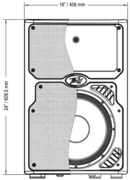
| Dimensions (H × W × D) | 62.2 cm × 40.9 cm × 38.1 cm |
| Weight | 17.7 kg (43 lbs) |
| Power Supply | 100-120 V or 220-240 V AC, 50/60 Hz, 110 W nominal |
| Protection | 5 A circuit breaker, thermal protection, DDT™ anti-clipping |
| Enclosure Material | Injection-molded ABS plastic, UL fire rating |
| Grille | Perforated steel with black powder coat finish (white available) |
| Mounting | M10 inserts (top/bottom) and M8 inserts (top/right side/bottom), Versamount 70+ bracket, 35 mm pole cup |
| Monitor Use | 45° bevel on right side for floor monitor placement |
| Optional Accessories | Extension module (wireless receiver, digital input, 10-band equalizer) |
| Maintenance and Cleaning | Disconnect before cleaning; use a dry cloth, avoid solvents; apply Armor-All type plastic protectant for finish |
| Safety | Do not open the enclosure; refer repairs to a qualified Peavey technician; never expose to rain or moisture |
| Spare Parts and Repairability | Peavey-specific parts: speaker, amplifier, extension module; repair by authorized service center |
| General Information | Manual available in French at notice-facile.com; estimated lifespan: 10 years with regular maintenance |
Frequently Asked Questions - PVXp 12 PEAVEY
User questions about PVXp 12 PEAVEY
0 question about this device. Answer the ones you know or ask your own.
Ask a new question about this device
Download the instructions for your Speaker in PDF format for free! Find your manual PVXp 12 - PEAVEY and take your electronic device back in hand. On this page are published all the documents necessary for the use of your device. PVXp 12 by PEAVEY.
USER MANUAL PVXp 12 PEAVEY
Two-Way Bi-Amped Sound Reinforcement Enclosure
Operating Manual
www.peavey.com
Intended to alert the user to the presence of uninsulated "dangerous voltage" within the product's enclosure that may be of sufficient magnitude to constitute a risk of electric shock to persons.
Intended to alert the user of the presence of important operating and maintenance (servicing) instructions in the literature accompanying the product.
CAUTION: Risk of electrical shock - DO NOT OPEN!
CAUTION: To reduce the risk of electric shock, do not remove cover. No user serviceable parts inside. Refer servicing to qualified service personnel.
WARNING: To prevent electrical shock or fire hazard, this apparatus should not be exposed to rain or moisture, and objects filled with liquids, such as vases, should not be placed on this apparatus. Before using this apparatus, read the operating guide for further warnings.

Protective earthing terminal. The apparatus should be connected to a mains socket outlet with a protective earthing connection.

aalal aalal alalal alal alal alal alal alal alal alal alal alal alal

aill 1000
12 2-4yS aalw jayll jbs:

Juslll lgl Jlsly pssuall Jxuul alj y, uall all y pa y s rual jyill jil .
Jg jglg 1000000000000000000000000000000000000000000000000000
P 120000000000000000000000000000000000000000000000

IMPORTANT SAFETY INSTRUCTIONS
WARNING: When using electrical products, basic cautions should always be followed, including the following:
- Read these instructions.
- Keep these instructions.
- Heed all warnings.
- Follow all instructions.
- Do not use this apparatus near water.
- Clean only with a dry cloth.
- Do not block any of the ventilation openings. Install in accordance with manufacturer's instructions.
- Do not install near any heat sources such as radiators, heat registers, stoves or other apparatus (including amplifiers) that produce heat.
- Do not defeat the safety purpose of the polarized or grounding-type plug. A polarized plug has two blades with one wider than the other. A grounding type plug has two blades and a third grounding plug. The wide blade or third prong is provided for your safety. If the provided plug does not fit into your outlet, consult an electrician for replacement of the obsolete outlet.
- Protect the power cord from being walked on or pinched, particularly at plugs, convenience receptacles, and the point they exit from the apparatus.
- Only use attachments/accessories provided by the manufacturer.
- Use only with a cart, stand, tripod, bracket, or table specified by the manufacturer, or sold with the apparatus. When a cart is used, use caution when moving the cart/apparatus combination to avoid injury from tip-over.
- Unplug this apparatus during lightning storms or when unused for long periods of time.
Refer all servicing to qualified service personnel. Servicing is required when the apparatus has been damaged in any way, such as power-supply cord or plug is damaged, liquid has been spilled or objects have fallen into the apparatus, the apparatus has been exposed to rain or moisture, does not operate normally, or has been dropped. - Never break off the ground pin. Write for our free booklet "Shock Hazard and Grounding." Connect only to a power supply of the type marked on the unit adjacent to the power supply cord.
- If this product is to be mounted in an equipment rack, rear support should be provided.
- Note for UK only: If the colors of the wires in the mains lead of this unit do not correspond with the terminals in your plug, proceed as follows: a) The wire that is colored green and yellow must be connected to the terminal that is marked by the letter E, the earth symbol, colored green or colored green and yellow. b) The wire that is colored blue must be connected to the terminal that is marked with the letter N or the color black. c) The wire that is colored brown must be connected to the terminal that is marked with the letter L or the color red.
- This electrical apparatus should not be exposed to dripping or splashing and care should be taken not to place objects containing liquids, such as vases, upon the apparatus.
- The on/off switch in this unit does not break both sides of the primary mains. Hazardous energy can be present inside the chassis when the on/off switch is in the off position. The mains plug or appliance coupler is used as the disconnect device, the disconnect device shall remain readily operable.
- Exposure to extremely high noise levels may cause a permanent hearing loss. Individuals vary considerably in susceptibility to noise-induced hearing loss, but nearly everyone will lose some hearing if exposed to sufficiently intense noise for a sufficient time. The U.S. Government's Occupational Safety and Health Administration (OSHA) has specified the following permissible noise level exposures:
Duration Per Day In Hours Sound Level dBA, Slow Response
| 8 90 | |
| 6 92 | |
| 4 95 | |
| 3 97 | |
| 2 100 | |
| 1 1/2 102 | |
| 1 105 | |
| 1/2 | 110 |
| 1/4 or less | 115 |
According to OSHA, any exposure in excess of the above permissible limits could result in some hearing loss. Earplugs or protectors to the ear canals or over the ears must be worn when operating this amplification system in order to prevent a permanent hearing loss, if exposure is in excess of the limits as set forth above. To ensure against potentially dangerous exposure to high sound pressure levels, it is recommended that all persons exposed to equipment capable of producing high sound pressure levels such as this amplification system be protected by hearing protectors while this unit is in operation.
a) The wire that is colored green and yellow must be connected to the terminal that is marked by the letter E, the earth symbol, colored green or colored green and yellow.
b) The wire that is colored blue must be connected to the terminal that is marked with the letter N or the color black.
c) The wire that is colored brown must be connected to the terminal that is marked with the letter L or the color red.
- i
- 1
- 无道之机可如以所至,自足而足。
- 1
- 期正用到电,期责有不实的
- 1
- 电
- Note for UK only: If the colors of the wires in the mains lead of this unit do not correspond with the terminals in your plug, proceed as follows: a) The wire that is colored green and yellow must be connected to the terminal that is marked by the letter E, the earth symbol, colored green or colored green and yellow. b) The wire that is colored blue must be connected to the terminal that is marked with the letter N or the color black. c) The wire that is colored brown must be connected to the terminal that is marked with the letter L or the color red.
- 2
| 8 90 | ||
| 6 92 | ||
| 4 95 | ||
| 3 97 | ||
| 2 100 | ||
| 1½ 102 | ||
| 1 105 | ||
| ½ 110 | ||
| 1¼ Ⅱ越高 | 115 |
OSHAe 1
aagai jaiy iay
jai jai gill, laa ayalni cllbajl alg yagshclpial piaiie: jia
CC
i1000100000001
C. = 1
3
4
.5
6
aaii 7
8
y j 9
y
Jalll jgagagagagagagagagagagagagagagagagagagagagagagagagagagagagagagagagagagagagagagagagagagagagagagagagagagagagagagagagagagagagagagagagagagagagagagagagagag
11
jagaiy aeg / ayal yajie d jia is ayal alalitie. jayal g e gill g iinall ldaa gll jilal, jnill, jnill, jnill, jnill
iie
13
14
aalal 2jna jsl sll sall aal
.16
17
jss sss sss sss sss sss sss sss sss sss sss
N 1
(20
18
19
J 1
20
Logo referenced in Directive 2002/96/EC Annex IV(OJ/L)37/38,13.02.03 and defined in EN 50419:2005
The bar is the symbol for marking of new waste and is applied only to equipment manufactured after 13 August 2005
Correct Disposal of this product. This marking indicates that this product should not be disposed with other house hold wastes throughout the EU. To prevent possible harm to the environment or human health from uncontrolled waste disposal, recycle it responsibly to promote the sustainable reuse of material resources. To return your used device, please use the return and collection systems, or contact the retailer where the product was purchased. They can take this product for environmental safe recycling.

FCC Compliancy Statement
This device complies with Part 15 of the FCC rules. Operation is subject to the following two conditions: (1) this device may not cause harmful interference, and (2) this device must accept any interference received, that may cause undesired operation.
Warning: Changes or modifications to the equipment not approved by Peavey Electronics Corp. can void the user's authority to use the equipment.
Note - This equipment has been tested and found to comply with the limits for a Class B digital device, pursuant to Part 15 of the FCC Rules. These limits are designed to provide reasonable protection against harmful interference in a residential installation. This equipment generates, uses and can radiate radio frequency energy and, if not installed and used in accordance with the instructions, may cause harmful interference to radio communications. However, there is no guarantee that interference will not occur in a particular installation. If this equipment does cause harmful interference to radio or television reception, which can be determined by turning the equipment off and on, the user is encouraged to try and correct the interference by one or more of the following measures.
- Reorient or relocate the receiving antenna.
- Increase the separation between the equipment and receiver.
- Connect the equipment into an outlet on a circuit different from that to which the receiver is connected.
- Consult the dealer or an experienced radio/TV technician for help.

Peavey Electronics Corporation · 5022 Hartley Peavey Drive · Meridian, MS · 39305
(601) 483-5365 • FAX (601) 486-1278 • www.peavey.com • 80305780 • ©2011
ENGLISH
PVXpTM 12
Thank you for purchasing the powered Peavey® PVXp™12. The PVXp 12 features an ultra-reliable, bi-amped power section that provides a total of 800 watts of peak available power with DDT™ compression. This powered enclosure also features a 12" heavy-duty woofer with a 2-3/8" voice coil and 50 oz. magnet, and the RX14™ compression driver with a 1.4" titanium diaphragm on a 100-degree horizontal x 50-degree vertical pattern asymmetrical horn. The PVXp 12 provides a balanced input via a combination jack that accepts balanced TRS 1/4" input as well as a balanced XLR input. There are two balanced Thru outputs, a male XLR and 1/4" TRS. There is an adjustable Level control as well as a combination LED indicator that illuminates when power is on and when the "soft-limiting" DDT circuit is activated, and a Contour switch for boosting lows and highs.
Features
- Two-way, bi-amped sound reinforcement enclosure
- 12" heavy-duty woofer with 2-3/8" voice coil & 50 oz. magnet
- RX14™ compression driver, with 1.4" titanium diaphragm
- Ultra-reliable, fan-cooled power amps with DDT™ protection
Total of 800W peak available power - Contour switch for boosting lows and highs
Patented Quadratic Throat Waveguide technology, 100 by 50 degree coverage - Asymmetrical horn aims the sound down 10 degrees, at the audience, not over their heads
- Input is via a combo female XLR and 1/4 TRS phone jack with balanced input
- Thru output is via an XLR and 1/4 TRS phone jack
- Durable, plastic, injection-molded trapezoidal enclosure
- Extra angled section on right side allows floor-monitor use
- Full-coverage heavy-duty perforated steel grilles, with powder-coat finish
- Pole mount molded-in for 1 - 3 / 8 diameter poles
- Top, bottom and right side flying point inserts
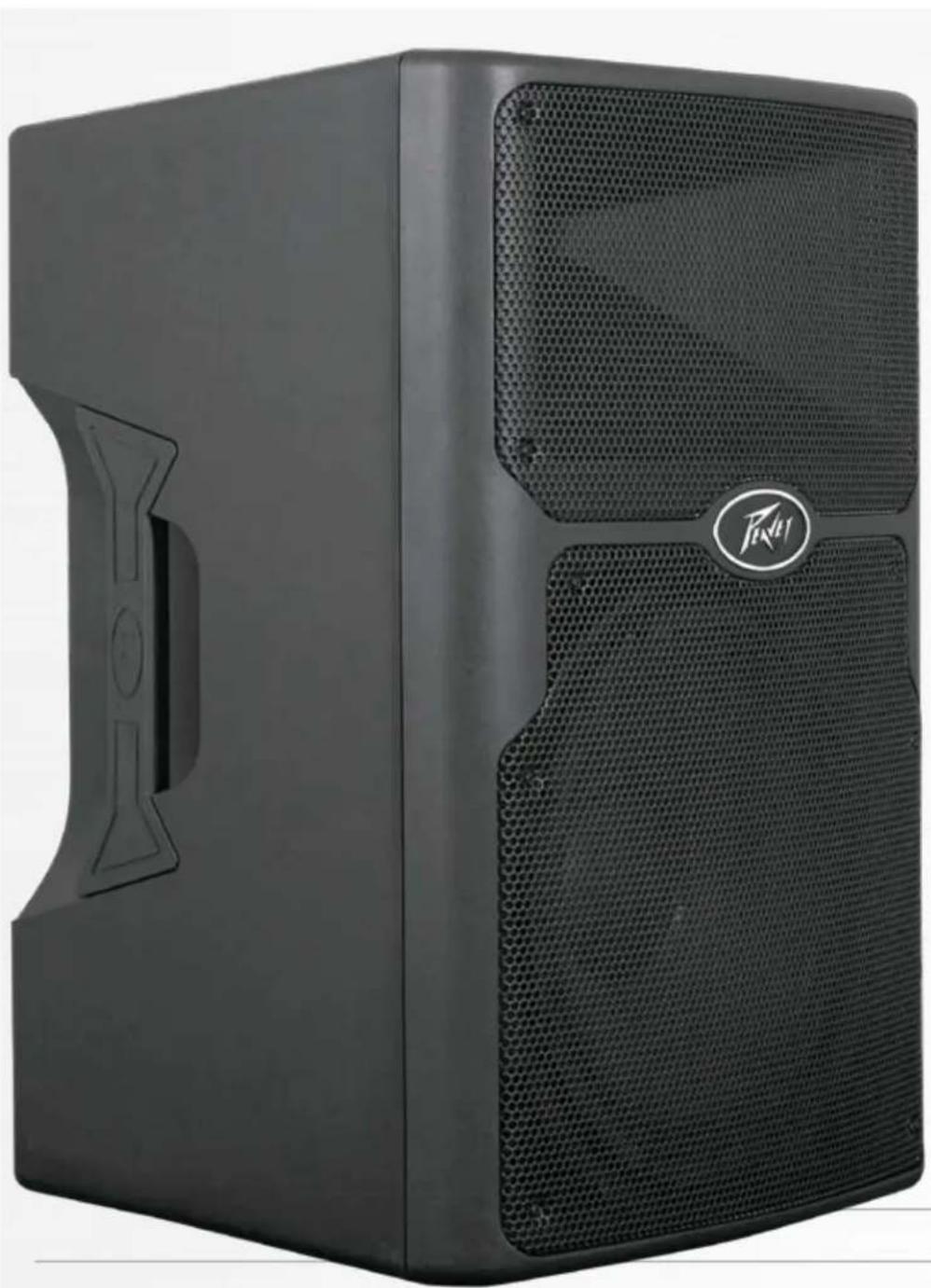
DESCRIPTION
The PVXp 12 is a two-way sound reinforcement system based on a heavy-duty Pro 12" woofer and a RX14 titanium diaphragm dynamic compression driver mounted on a 100 by 50 degree coverage Quadratic Throat Waveguide. Its sleek, modern appearance, coupled with excellent performance, offer an outstanding package. The lightweight-yet-rugged injection-molded plastic enclosure with molded-in stand mount cup facilitates portable use for live music or P.A. sound. The trapezoidal cabinet has three handles for ease of portability, and an extra 45-degree angled section on the right side to allow use as a floor monitor. Five sets of flying/mounting points, two on the top, two on the bottom, and one on the side, with a total of 16 cabinet inserts, provide for the ultimate in installation flexibility. A black, powder-coated, perforated steel grille provides driver protection and a professional appearance.
The heavy-duty 12" woofer has a 2-3/8" voice coil diameter, and a 50 oz. magnet for 200 watts continuous worth of chest-pounding bass. The RX14 compression driver tweeter is coupled to a Quadratic Throat constant directivity waveguide, covered under US patent #6,059,069, with smooth, even response, low distortion and good high frequency dispersion. This horn has an asymmetrical vertical polar response, aiming the main energy lobe down 10 degrees, so it is directed at the audience instead of over their heads. The vertical polar pattern is +15 degrees, -35 degrees. This helps reduce ceiling reflections for greater clarity and gain before feedback.
The PVXp 12 speaker system power amplifiers providing the bi-amplification are low-distortion, ultra-reliable, fan-cooled units providing a total of 800W peak available power for the system. There is 650W peak available power for the woofer, and 150W peak available power for the tweeter. The power supply for both amps is a switchmode type for low weight and high efficiency. Both amplifiers feature our DDT™ compression, which virtually eliminates audible power amplifier clipping. Cooling is provided via a low-noise fan for reliable operation under strenuous conditions.
Input is via a combo female XLR and 1/4 TRS phone jack with balanced input to the preamp/EQ electronics, and a level control. A Thru output has an XLR and a TRS 1/4 phone jack connector. These outputs allow the user to link additional speaker systems, or feed the signal to a powered subwoofer, etc. Included in the input panel is a bay for optional function modules, such as a Wireless Receiver, Digital Audio Input or a 10-band EQ, etc.
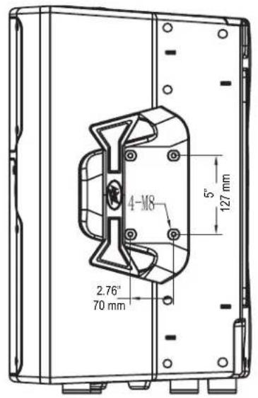
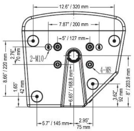
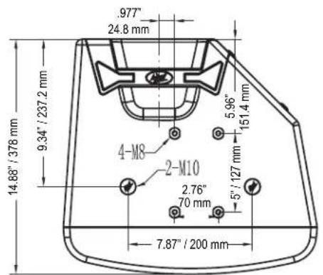
The cabinet of the PVXp™12 speaker system has multiple mounting fly points, providing outstanding versatility in permanent installations. A pair of M10 inserts is molded-in to the top, and a pair on the bottom, while a set of four M8 inserts are available on the top, on the bottom, and on the right side in the handle recess. This is a total of 16 mounting inserts in all. All of these inserts have retaining hardware on the inside of the plastic cabinet, providing a more reliable and safe mode of mounting the cabinet.
APPLICATIONS
The Peavey PVXp 12 has a variety of applications such as sound reinforcement, public address, side fill system, karaoke or musical playback.
A typical signal source for the line-level inputs of the Peavey PVXp 12 would be a sound reinforcement mixing console (mixer) or the output from a CD player, MP3 player or similar device. A high-output dynamic microphone can be connected directly via the XLR input and used, as well.
REAR PANEL
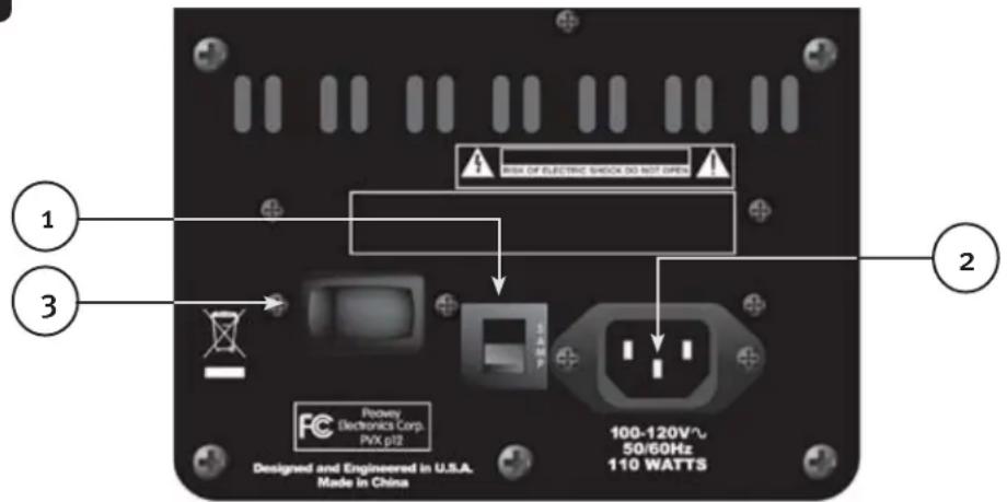

CIRCUIT BREAKER (1)
The unit is AC power line protected from overloads and fault conditions with a 5-amp circuit breaker. This breaker should not trip unless there is a fault in the amplifier circuitry or an abnormal operating condition, which causes excessive mains current to flow. If the breaker trips, set the Power switch (3) to OFF, and after waiting a brief period of time for the breaker to cool, reset the breaker.
If the circuit breaker trips, the center button will pop outward approx. 1 / 4 and can be reset by pushing upward and inward. Under normal (not tripped) conditions, the center button is relatively flat.
If the unit continues to trip the breaker, or trips it immediately after being reset, do not keep resetting it, the system should be taken to a qualified Peavey Service Center for repair.

IEC POWER CORD CONNECTION (2)
This receptacle is for the IEC line cord (supplied) that provides AC power to the unit. It is very important for the user to ensure that the PVXp 12 has the proper AC line voltage supplied. You can find the proper voltage for your PVXp 12 printed next to the IEC line (power) cord on the rear panel of the unit.

Please read this guide carefully to ensure your personal safety as well as the safety of your equipment. Never break off the ground pin on any equipment. It is provided for your safety. If the outlet used does not have a ground pin, a suitable grounding adapter should be used and the third wire should be grounded properly. To prevent the risk of shock or fire hazard, always be sure that the mixer and all other associated equipment are properly grounded.
ON-OFF SWITCH (3)
This rocker switch supplies AC power to the PVXp 12 when switched to the ON position. The ON position is with the left side of the switch pushed "in" or nearly flush with the rear panel.
REAR PANEL TOP
ACCESS PANEL FOR OPTIONAL EXPANSION MODULE
This panel is to be removed ONLY when installing one of a variety of Optional Expansion Modules that will be available soon for the PVXp 12.
These Optional Expansion Modules will either work in conjunction with the input already present on the PVXp 12, or provide an in-line function for the input, such as a 10-band EQ, etc. Check with your Peavey dealer for availability and price.
If you are not installing such an optional Expansion Module, then do not remove this cover. Instructions for installing an optional expansion module will come with each expansion module and will be specific for that module.
TOP - OPERATING CONTROLS, INPUTS & OUTPUTS
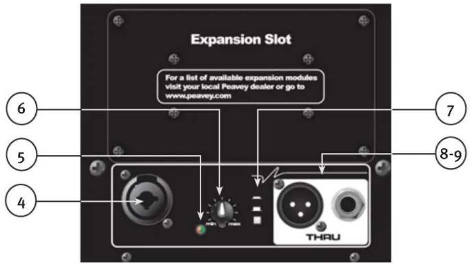

INPUT (4)
The line-level input is of the medium impedance balanced type. The jack is a combo female XLR and 1/4'' TRS connector.
SPECIAL NOTE! The normal input for line level is the 14 TRS jack. It has reduced gain compared to the XLR input, which has enough gain for a high-output microphone to be used with the Level control. Sensitivity of the 14 TRS jack is 0.54 volts for full output, and 0.12 volts for the XLR jack.
LED (5)
Illuminates green when the power switch is On and power is present. It turns red when either of the power amps engages the DDT™ "soft limiting" circuitry.
LEVEL (6)
Controls the gain or output level of the input signal. It is used to directly set the system output level for a given input channel input signal.
CONTOUR (7)
The Contour switch provides a mild boost at the frequency extremes, so that low-level playback can be more pleasing. Do not use the Contour switch when playing sound at loud levels, as the boost is not needed then.
THRU JACKS (8 & 9)
These jacks are intended for the use of linking multiple PVXp™12 enclosures in a line or to provide a feed to a powered subwoofer, or other electronics that needs to receive a full-range version of the input signal. The connectors available are a male XLR jack (8), and a 1/4 TRS phone jack (9).
OPERATING INSTRUCTIONS
CAUTIONS:
The unit must be disconnected from the AC power source before any work is done on it. Refer all servicing to qualified service personnel.
The back plate can become hot to the touch. Do not block or cover the fan or the exhaust louvers from ventilation. There must be a minimum of 4 of space behind the fan. Do not allow the airflow to become blocked by objects such as curtains or drapes, thermal building insulation, etc. It is recommended that the rear of the PVXp 12 not be placed in a closed space or a space that has no fresh, cool airflow.
Be sure to keep the microphone away from the front of the speaker after connecting it to the input, and while setting the microphone level, or very loud feedback will occur! Damage to the system is likely if this occurs!
DO NOT connect the inputs of the PVXp 12 to the output of a power amplifier. The inputs are meant to be driven from a line-level strength signal.
DO NOT remove the protective metal grilles.
WARNING! The PVXp 12 is very efficient and powerful! This sound system can permanently damage hearing! Use extreme care when setting the overall maximum loudness!
The apparent sound level of the PVXp 12 can be deceiving due to its clear, clean sound output. The lack of distortion or obvious distress can make the sound level seem much lower than it actually is. This system is capable of SPLs in excess of 127dB at 1M from the speaker!
FLYING THE PVXP12
IMPORTANT SAFETY INFORMATION FOR THE MOUNTING AND FLYING OF THE PEAVEY PVXp 12
CAUTION: Before attempting to suspend this speaker, consult a certified structural engineer. Speaker can fall from improper suspension, resulting in serious injury and property damage. Other enclosures may NOT be suspended below one, nor should additional weight be suspended from one of these units. Use only the correct mating hardware. All associated rigging is the responsibility of others.
Maximum enclosure angle from vertical hang is 30 degrees.
Always use a suitable safety chain or wire rope, attached to an unused group of fly points or to the cabinet as directed by a certified structural engineer, and firmly attached to a suitable structural member as indicated by a certified structural engineer.
The recommended range of torque for the mounting bolts is 3.5 to 4.0 foot-lbs. (4.75 to 5.42 N-m). DO NOT OVERTIGHTEN! If an insert spins free, it has been damaged, and the cabinet can not be safely flown from that set of inserts!
Never transport the cabinet while mounted on an array bracket or other mounting bracket, as this may unduly stress the mounting inserts.
The use of threadlocker (blue type/medium strength) on the mounting bolts is recommended, as are the appropriate lock washers, to ensure that the mounting hardware will not vibrate loose over time.
GROUPING OF INSERT SETS
Group A
A set of two M10 inserts on the top, designed to hang the cabinet using the proper eyebolts.
Group B
A set of two M10 inserts on the bottom, designed to hang the cabinet using the proper eyebolts.
Group C
A set of four M8 inserts on the top, designed to be used with the Peavey Versamount™ 70+ mounting bracket.
Group D
A set of four M8 inserts on the right side, designed to be used with the Peavey Versamount 70+ mounting bracket.
Group E
A set of four M8 inserts on the bottom, designed to be used with the Peavey Versamount 70+ mounting bracket.
For Group A and B, always use both inserts as a pair; NEVER use just one insert to fly a cabinet!
For Group C, D and E, Always use all four inserts of a given group as a set; NEVER use just one insert to fly a cabinet! The four insert groupings are meant to have all four inserts used at once within a group.
Group E should only be used with the Versamount 70+ oriented beneath the cabinet, and at an angle less than 30 degrees from vertical.
SPECIFICATIONS FOR INSERT MATING HARDWARE
Group A and Group B should use an M10 forged steel shoulder-type lifting eyebolt, which meets the requirements of DIN 580 or ASTM A489. They should only be used in pairs, and in conjunction with the rear most pair of M8 inserts on the same surface as a pull-back/aiming adjustment, using M8 eyebolts of a similar specification. The length of the threaded shank on the eyebolts should not exceed 3 / 4 (approx. 20mm ), so that it does not bottom-out in the insert. Thread pitch: 1.5mm per thread.
Group C and D should use an M8, grade 8.8 or better, 1.25mm per thread, metric bolt, that does not penetrate the cabinet beyond the cabinet surface more than 3/4 (approx. 20mm ). When using a Peavey Versamount 70+ mounting bracket and lock washer, the length of the bolt should not exceed 1.125 (approx. 30mm ).
Group E should use an M8, grade 8.8 or better, 1.25mm per thread, metric bolt, that does not penetrate the cabinet beyond the cabinet surface more than 0.472^ (12 mm). When using a Peavey Versamount 7o+ mounting bracket and lock washer, the length of the bolt should not exceed 3 / 4 approx. 20~mm
WARNING! (note to structural engineer)
The thread insertion depth past the surface of the cabinet of the end of the mounting bolt should not be more than 0.787" (20 mm) for insert groups A, B, C and D, and not more than 0.472" (12 mm) for Group E.
If these thread insertion depths are exceeded, then the inserts may be damaged or unseated from the cabinet, severely compromising the mounting integrity of the cabinet!
For maximum mounting strength, safety and reliability, the bolt threads should engage at least 10 mm of depth for Group A and B, and at least 8 mm of depth for groups C, D and E.
The PVXp™ 12 mounting insert groups C, D and E are designed to be used with the Peavey Versamount 70 Plus mounting bracket (oo45447o black, oo45446o white), as well as the Impulse ® 12" array bracket (oo386920 black, oo38694o white). It can also be used with the Peavey Wall-Mount Speaker Stand (oo92294o black, oo48739o white), which will fit into the built-in stand mount cup on the bottom of the cabinet.
CONNECTING AC POWER TO THE PVXP 12
The PVXp 12 comes with a 6-foot IEC connection AC power cord. If you are using an extension cord or power strip with this powered speaker, make sure it is of good quality and of a sufficient current capacity to maintain safety and maximize the power output capability of the PVXp 12. For maximum undistorted output, do not connect any other device to the same extension cord that the PVXp 12 is connected to. Do not exceed the rated current capacity of the extension cord with the sum total of all units connected to it.
When first plugging in the AC cord, make sure the power switch is in the OFF position, and then turn it ON only once the power cord has been connected. Built-in muting will engage when the proper sequence of steps is taken.
SPECIAL NOTE FOR PERMANENT INSTALLATION
When installing the PVXp 12, AC power runs will be used and a certified electrician should be consulted to be sure that all AC wiring complies with local codes and regulations. It is also advisable to use a cable clip properly affixed

to the cabinet to strain relief the IEC power cord connected to the amplifier module at (2) so the power cord cannot be pulled out or vibrate loose.
USE OF THE PVXP™ 12 WITH A SUBWOOFER POLE TUNNEL
The built-in stand-mount cup allows use with the Peavey SP 118 Sub and the accessory pole that it is designed to use, Peavey part #00326530. The pole used is 51 - 3 / 4 long and has a nominal diameter of 1 - 3 / 8 Always be sure to place the subwoofer used in this manner on a flat, level and stable surface.
USE OF THE PVXP 12 WITH A SPEAKER STAND
The PVXp 12 has a stand=mount cup molded-in so that the system can be stand mounted on a standard 1-3/8" (36mm) diameter stand pole. When using stands or poles, be sure to follow these precautions:
Check the stand or pole specs to make sure that it can support the weight of the PVXp 12 (43 lbs./19.5 kg), and observe all safety precautions stated by the stand manufacturer, including the maximum height the stand is rated for.
Always place the stand on a flat, level and stable surface, and be sure to fully extend the stand legs as per the stand manufacturer's instructions.
Try to make sure that the stand legs are oriented for the least danger of tripping to those in the vicinity of the stand. Never block a doorway or hallway with the legs of a stand.
Try to route cables so that people will not trip over them, or tip the speaker over. Use of duct tape, cable channels or guards, or other appropriate tie-down/cover-up devices should be carefully considered and implemented.
When installing or de-installing the speaker on the stand, it is a good practice to have a helper if possible, as it can be hard to "thread the needle" and mate the stand cup to the stand pole while holding the PVXp 12 speaker system at arm's length. It is also helpful if someone holds the speaker stand and pole down while the PVXp 12 is removed from the stand pole. This prevents the PVXp 12 from pulling the pole up with it.
When using stands outdoors, never attach banners or flags to the stands or the PVXp 12 speaker system, strong winds may cause the speaker to blow over. If there is a possibility of windy conditions, then it may be prudent to consider weighting or locking down the stand legs to prevent the PVXp 12 speaker system from being blown over.
CONNECTING A SIGNAL TO THE PVXP 12
There are a variety of ways to input a signal to the PVXp 12.
The input (4) provides either a balanced mic- or line-level input, allowing the use of a 1/4 TRS (tip-ring-sleeve) type phone plug or a male XLR plug.
Do not connect cables to the jacks while the unit is ON and the Level knob is turned up! While a standard single-ended 1/4'' phone plug-equipped cable will work well and the balanced input circuitry will provide some interference rejection, a balanced cable using either the balanced TRS 1/4'' phone plug or the XLR plug will provide superior interference rejection and performance.
Sometimes, with difficult interference problems, it will be helpful to lift the shield ground ( Pin #1 of an XLR) of a balanced cable at the PVXp 12 end. Check any input changes carefully, always turning the Level control down before plugging and unplugging cables, or lifting the ground.
Use of high-quality, premium cables is recommended for the PVXp 12, as these usually have better shielding and materials and will provide greater long-term reliability. The best option is a shielded, balanced cable no longer than necessary to reach the PVXp 12. It is usually a good idea to leave some slack at the input to the PVXp 12 and also to tape the cables down or run them under a cable guard to avoid anyone tripping over them or pulling the PVXp 12 over when stand mounted.
LEVEL CONTROL ADJUSTMENT
The PVXp 12 is equipped with a Level control (6) on the input to facilitate use in many different applications.
With the Level control adjusted fully clockwise, gain is at maximum and the input sensitivity is 0.54 V RMS for full-rated output with the 1/4 TRS jack, and 0.12 V RMS with the XLR portion of the jack. When driving the PVXp™ 12 from a mixer, it may be advantageous to reduce the input sensitivity by turning the Level control to the halfway point. The PVXp 12 will now more closely match a typical power amp.
If the mixing board indicates clipping of its output signals, then all of the PVXp 12 power capability is not being utilized cleanly. Clipping the signal before it gets to the PVXp 12 is not optimal. Reduce the mixer output level and turn up the Level control on the PVXp 12. The amplifiers in the PVXp 12 are equipped with DDT™, and the LED indicator will show when DDT has engaged. If the sound seems heavily compressed, check these indicators; if it is blinking RED more than occasionally, then the drive level from the mixer (or the Level control on the PVXp 12) needs to be reduced.
When first turning on the sound system, switch on all upstream electronics first, then the PVXp 12 with its Level control fully counterclockwise (all the way down). Begin checking levels with the mixer output level controls all the way down, and bring them up slowly with the PVXp 12 Level control set to the desired setting (one-third recommended to start).
It is not good practice to turn the Level control on the PVXp 12 all the way up and then try to control level only from the mixer; this approach would tend to pick up excess noise. The best practice would be to run a "hot" signal from the mixer down the cable to the PVXp 12, and then turn the PVXp 12 Level control up only as much as necessary to reach the full desired output. With this approach, it is necessary to verify the mixer output is not clipping.
DISCONNECTING AC POWER TO THE PVXP 12
We recommend that the Power switch (3) be used to turn the unit off first, and then the AC power cord can be removed. This minimizes stress to the power amplifiers and the transducers from turn-off transients. The power switch has an arc suppression capacitor to help during turn-off, and tends to make a clean disconnect from the AC power, while the power cord IEC connector can make intermittent contact before finally becoming fully disconnected, e.g., as when wiggling the cord.
TROUBLESHOOTING
No Output at All
First, make sure the unit has AC power and is turned ON. Make sure the LED on the power amp module is illuminated.
If not, make certain the ON/OFF switch (3) is in the ON position and check the IEC power cord connection (2) by ensuring it is fully engaged and seated. Make certain the AC line cord is plugged into a working AC outlet. Finally, check the breaker (1). (See the Rear Panel: Breaker section, for safety instructions.)
Once assured your unit is getting AC power, check that the PVXp 12 is getting a signal. Temporarily disconnect the cable running to its inputs and connect it to some other device capable of reproducing the signal (i.e., a power amp and speaker). If this produces a signal, make sure that all Level controls being used have been turned up to a satisfactory level (one-third to halfway).
If the PVXp 12 has been subjected to direct sunlight or excessive heat, the built-in thermal protection may have been triggered. If so, turn off the PVXp 12 and let it cool for a sufficient amount of time.
If there is still no output, contact your authorized Peavey ^® dealer or the Peavey International Service Center.
Hum or Buzz
If the PVXp 12 is producing a hum or buzz, this can be AC outlet related. Try plugging the PVXp 12 into a different AC outlet. Sometimes, if a different circuit (breaker) is used for the mixer and for the PVXp 12, it can cause hum problems. Unless it is not practical, it is best to use the same wall outlet (breaker) to supply power to both the mixer and the powered speaker.
Ensure that shielded cables have been used to route the signal to the PVXp 12's input. If speaker cables with 1/4'' plugs are used as input cables instead of shielded cables, they will be prone to hum or buzz.
Hum may be ground loop related. It may be helpful to lift the shield ground (Pin #1) on a balanced cable at the PVXp 12 end. Check any input changes carefully by first turning down the Level control, before plugging and unplugging cables, or lifting the shield ground at the speaker end.
Check to make sure light dimers are not on the same circuit as the PVXpTM 12, the mixer or any source devices. If light dimmers are used, then it may be necessary to turn them fully ON or fully OFF to eliminate or reduce hum. This is a typical AC wiring/light dimmer interference problem, not a design flaw of the PVXp 12.
The third wire (ground plug) on the AC plug should NEVER be removed or broken off, as this is a potential safety hazard.
Distorted or Fuzzy Sound
First, ensure the mixer (signal source) is not clipping or being overdriven. Make sure the Level (6) control on the PVXp 12 has not been set too low. Check that the input plug is fully seated in the input jack on the rear panel of the PVXp 12. Ensure that a power amp has not been plugged into the input jack of the PVXp 12. If an extension cord is being used to provide the AC power to the unit, ensure that it is of sufficient current capacity and that it is not also being used to supply power to any other device.
The PVXp 12 has a built-in Contour EQ button to extend and smooth the natural response of the speakers in the system. When the Contour button is engaged, some Bass boost and HF EQ have been applied and the system then has a nominally balanced response for background music, so it should require little, if any, additional EQ. If excessive additional bass boost or HF boost have been added externally to the PVXp 12, it could cause premature overload at high SPL. Reduce the amount of any external (mixer, rack) EQ and see if that clears up the distortion.
Check to make sure that a line level signal is not being input through the XLR jack, this has 13 dB more gain than the 1 / 4 TRS jack, and could be overloading with high mixer output levels.
Finally, realize that even though the PVXp 12 is a powerful and high output unit, it does ultimately have limits, and it may need additional powered units (or a subwoofer) to provide enough sound output or coverage. In this case, try turning the mixer levels down a little to see if that clears things up. If, after checking all the things listed to check and anything else you can think of to check safely, and the system still exhibits problems, carefully note all conditions and check with your Peavey dealer for advice.
CARE AND MAINTENANCE
Your PVXp 12 is a sturdy and durable product and will provide years of reliable use if properly cared for. Use common sense and read the safety warnings to avoid hazardous operating conditions.
The unit must be disconnected from the AC power source before any work is done on it. Refer all servicing to qualified service personnel.
Sunlight/Heat
Avoid prolonged exposure to direct sunlight, as this may cause the unit to overheat and thermally shut off. Excessively hot operating conditions can also cause a thermal shutdown. Do not store in extremely hot or cold conditions or extremely high humidity. Always allow unit to come to room temperature before use.
Cleaning
Never clean the PVXp 12 while plugged in or turned ON! When the unit has been fully disconnected from AC power sources, use a dry cloth to remove soil or other dirt. Never use strong solvents on the PVXp 12, as they could damage the cabinet. Do not allow ANY fluids to drip inside the PVXp 12.
Touchup
For an overall finish enhancement and protective coating, use gloves to apply a plastic finish protector, such as Armor-All® protectant or a similar product, to the surface of the plastic cabinet only. Note that the cabinet will be slippery after these treatments; rub them down vigorously with a dry, lint-free cloth to minimize this.
Check for Secure Hardware
After the first few months of use and periodically thereafter, check the hardware of the PVXp 12 for tightness, including the rear panel screws and the screws that hold the baffle and rear cabinet together. The unit is subject to a great deal of vibration, and this could cause them to loosen with use.
ARCHITECTURAL AND ENGINEERING SPECIFICATIONS
The powered loudspeaker system shall have a frequency response from 60Hz to 20kHz . The peak SPL with inaudible distortion shall reach 127 dB with music as a source, when measured at a distance of 1M and driven to full output capacity. The system shall utilize a Peavey® Pro 12 12" heavy-duty woofer and a Peavey RX™ 14 1.4" titanium diaphragm dynamic compression driver. The nominal radiation pattern shall be 100^ in the horizontal plane, and 50^ in the vertical plane. Axis of the vertical main polar lobe is angled down 10 degrees, resulting in the angular pattern with respect to straight ahead being +15, -35 degrees.
The powered, bi-amplified loudspeaker system shall have an input channel consisting of a medium impedance input connector consisting of one combo female XLR and 1/4 TRS phone jack on the rear panel.
The input section shall have a Contour EQ system activated by a pushbutton that provides for boost at the low and high frequencies of about 5 dB relative to the midrange.
There shall be a group of Thru (output) connectors consisting of a male XLR jack, and a 1/4 TRS phone jack.
The system power amplifiers shall have an unfiltered frequency response of 20Hz to 20kHz which deviates no more than +0, -3 dB up to rated power, a damping factor greater than 100 @ 1 kHz into 8 ohms, hum and noise better than 90 dB below rated power, and THD and IMD of less than 0.5% .
The woofer amplifier shall be capable of 325W continuous before thermal pull-back to into an 8 ohm nominal load, and the tweeter amplifier shall be capable of 75W continuous output into a 8 ohm load, and both shall incorporate independent DDT compression.
The input signal shall be electronically divided into high frequencies and low frequencies by a staggered pole fourth order slope line-level crossover at 2.8kHz . The low frequencies shall be processed to provide bass boost, subsonic filtering and overall response shaping, and the high frequencies shall be equalized for response-shaping.
The enclosure shall be constructed of injection-molded ABS with a UL flame rating, and reinforcing ribs internally. A handgrip shall be incorporated on each side near the woofer and towards the front, and on the right side of the cabinet.
A separate powder-coated metal grille shall be provided for horn and woofer protection. The cabinet shall incorporate a pole mount for speaker stand use, four tall sturdy rubber feet for floor standing use, and a group of four mounting point inserts on the top and bottom each, and on the right side, for flying use.
The outside dimensions shall be: 24.50" (62.2 cm) tall x 16.10" (40.9 cm) wide x 15.00" (38.1 cm) deep, and the weight shall be 43 lbs. Power requirements shall be: 370 Watts nominal, 100-120 VAC, 50/60 Hz Domestic and 220-240 VAC, 50/60 Hz (Export). The loudspeaker system shall be called a Peavey PVXp™ 12.
GENERAL SPECIFICATIONS
Frequency Range, 1 meter on-axis, swept-sine in 12 Space environment: 51 Hz to 20 kHz
Frequency Response, 1 meter on-axis, swept-sine in anechoic environment: 60Hz to 20kHz(± 3dB)
Usable Low Frequency limit (-10 dB point anechoic): 55 Hz
Nominal sensitivity (1W @1M, swept sine input in anechoic environment): 97 dB (average)
Maximum Sound Pressure Level (1 meter): 127 dB SPL peak with music
Radiation Angle measured at -6 dB point of polar response: Nominal: 100 degrees horizontal X 50 degrees vertical (Axis of the vertical main polar lobe is angled down 10 degrees, resulting in the angular pattern with respect to straight ahead being +15, -35 degrees)
Transducer Complement: Heavy-duty 12" woofer with 2-3/8" voice coil & 50 oz. magnet, RX™14 1.4" titanium diaphragm dynamic compression driver
Box Tuning Frequency: 62 Hz
Electroacoustic crossover frequency: 2,800 Hz
Crossover type: Internal Electronic two-way crossover with driver EQ, level matching, bass boost and subsonic filtering.
Crossover Slopes: 24 dB/octave (4th order) low pass, 24 dB/octave (fourth order) high pass, both with staggered poles and driver EQ.
Input Connections:
One combo female XLR and 1/4 " phone jack providing balanced line-level operation from the 1/4 " jack section, and high-output dynamic microphone operation from the XLR section.
Output Connections: One male XLR and one 1/4 phone jack. The Thru jacks are intended for the use of linking multiple PVXp™12 enclosures in a line or to provide a feed to a powered subwoofer, or other electronics that needs to receive a full range version of the input signal.
Enclosure Materials & Finish: Black ABS plastic with textured surface, black powder-coated perforated grille. Also available in white.
Mounting provisions: Unit has two sets of two M10 inserts, one pair on the top, and one pair on the bottom. Additional mounting points are a set of four M8 inserts on the top, and a set of four on the right side in the handle recess, and a set of four on the bottom, which use the Peavey Versamount 70+ mounting bracket. Four rubber feet provide vibration free floor or stage use, and a molded-in stand mounting cup is on the bottom.
Front: 24.50 in. x 16.10 in. x 15.00 in. 622 mm x 409 mm x 381 mm
Rear: 22.75 in. x 8.75 in. x 15.00 in. 578 mm x 222 mm x 381 mm
Net Weight: 43 lbs. (19.5 kg)
ELECTRONICS AND AMPLIFIER SPECIFICATIONS:
Internal power amplifiers (@120 VAC line):
Total of 800 watts peak available power
Woofer - 650 watts peak available power
Continuous Power*: 325 watts @ less than 1% distortion
Tweeter - 150 watts peak available power
Continuous Power: 75 watts @ less than 1% distortion.
- Before thermal pull-back activates.
Electronic Input Impedance (Nominal):
Line: 2.2k ohms balanced (1 / 4^ ) , 10 k ohms unbalanced 1 / 4^
Mic: 2.2 k ohms balanced (XLR) No phantom power available.
Input Sensitivity for Full Output (Level full CW): 1/4" TRS Phone jack - 0.54 V RMS, XLR jack - 0.12 V RMS
Infrasonic filter protection: 36 dB/octave roll-off
Nominal Amplifier Frequency Response: +0, -3 dB from 20 Hz to 20 kHz
Hum and Noise: Greater than 90 dB below rated power
DDT™ Dynamic Range: Greater than 21 dB
THD and IM: Typically less than 0.5%
Damping Factor: Greater than 100 @ 1000 Hz, 8 Ohms
Power requirements of Peavey PVXp 12 System: Nominal 370 Watts, 100-120 VAC 50-60 Hz


Features and specifications are subject to change without notice.
Peavey Electronics Corporation • 5022 Hartley Peavey Drive • Meridian • MS • 39305 (601) 483-5365 • FAX (601) 486-1278 • www.peavey.com • ©2012 Printed in the U.S.A. EX000155
ESPANOL
PVXpTM 12
Avant: 24.50 in. x 16.10 in. x 15.00 in. 622 mm x 409 mm x 381 mm
Arrière: 22.75 in. x 8.75 in. x 15.00 in. 578 mm x 222 mm x 381 mm
Poids net: 43 lbs. (19,5 kg)
SOSPENSIONEL PVXP 12
INFORMAZIONI DI SICUREZZA IMPORTANTI PER IL MONTAGGIO E LA SOSPENSIONE DEL PEAVEY PVXp 12
Effective Date: 09/15/2010
What This Warranty Covers
Your Peavey Warranty covers defects in material and workmanship in Peavey products purchased and serviced in the U.S.A. and Canada.
What This Warranty Does Not Cover
The Warranty does not cover: (1) damage caused by accident, misuse, abuse, improper installation or operation, rental, product modification or neglect; (2) damage occurring during shipment; (3) damage caused by repair or service performed by persons not authorized by Peavey; (4) products on which the serial number has been altered, defaced or removed; (5) products not purchased from an Authorized Peavey Dealer.
Who This Warranty Protects
This Warranty protects only the original purchaser of the product.
How Long This Warranty Lasts
The Warranty begins on the date of purchase by the original retail purchaser. The duration of the Warranty is as follows:
| Product Category Duration | |
| Guitars/Basses, Amplifiers, Preamplifiers, Mixers, Electronic Crossovers and Equalizers 2 years * (+ 3 years) | |
| Drums 2 years * (+ 1 year) | |
| Enclosures 3 years * (+ 2 years) | |
| Digital Effect Devices and Keyboards and MIDI Controllers 1 years * (+ 1 year) | |
| Microphones 2 years | |
| Speaker Components 1 year(incl. Speakers, Baskets, Drivers, Diaphragm Replacement Kits and Passive Crossovers) | |
| Tubes and Meters | 90 Days |
| Cables Limited Lifetime | |
| AmpKit Link, Xport, Rockmaster Series, Strum'n Fun, RetroFire, GT & BT Series Amps | 1 year |
* Denotes additional Warranty period applicable if optional Warranty Registration Card is completed and returned to Peavey by original retail purchaser within 90 days of purchase.
What Peavey Will Do
We will repair or replace (at Peavey's discretion) products covered by Warranty at no charge for labor or materials. If the product or component must be shipped to Peavey for Warranty service, the consumer must pay initial shipping charges. If the repairs are covered by Warranty, Peavey will pay the return shipping charges.
How To Get Warranty Service
(1) Take the defective item and your sales receipt or other proof of date of purchase to your Authorized Peavey Dealer or Authorized Peavey Service Center.
OR
(2) Ship the defective item, prepaid, to Peavey Electronics Corporation, International Service Center, 412 Highway 11 & 80 East, Meridian, MS 39301. Include a detailed description of the problem, together with a copy of your sales receipt or other proof of date of purchase as evidence of Warranty coverage. Also provide a complete return address.
Limitation of Implied Warranties
ANY IMPLIED WARRANTY, INCLUDING WARRANTY OF MERCHANTABILITY AND FITNESS FOR A PARTICULAR PURPOSE, ARE LIMITED IN DURATION TO THE LENGTH OF THIS WARRANTY.
Some states do not allow limitations on how long an implied Warranty lasts, so the above limitation may not apply to you.
Exclusions of Damages
PEAVEY'S LIABILITY FOR ANY DEFECTIVE PRODUCT IS LIMITED TO THE REPAIR OR REPLACEMENT OF THE PRODUCT, AT PEAVEY'S OPTION. IF WE ELECT TO REPLACE THE PRODUCT, THE REPLACEMENT MAY BE A RECONDITIONED UNIT. PEAVEY SHALL NOT BE LIABLE FOR DAMAGES BASED ON INCONVENIENCE, LOSS OF USE, LOST PROFITS, LOST SAVINGS, DAMAGE TO ANY OTHER EQUIPMENT OR OTHER ITEMS AT THE SITE OF USE, OR ANY OTHER DAMAGES WHTHER INCIDENTAL, CONSEQUENTIAL OR OTHERWISE, EVEN IF PEAVEY HAS BEEN ADVISED OF THE POSSIBILITY OF SUCH DAMAGES.
Some states do not allow the exclusion or limitation of incidental or consequential damages, so the above limitation may not apply to you.
This Warranty gives you specific legal rights, and you may also have other rights which vary from state to state.
If you have any questions about this Warranty or services received or if you need assistance in locating an Authorized Service Center, please contact the Peavey International Service Center at (601) 483-5365.
Features and specifications are subject to change without notice.
Optional Product Extended Warranty Registration
Give us some information and put your extended warranty into effect!
Please take a few minutes to fill out this information/survey sheet to help us get to know and serve you better.
To save time, submit your warranty registration online at www.peavey.com/support/warrantyregistration
1.
First Name
Initial Last Name
Street Address
- How did you learn about this Peavey product? (select best answer)
Magazine review
Teacher's recommendation
□ Newspaper review
Catalog or flyer
Radio advertisement
Saw in store
□Advertised special
Use by professional
□ Friend/Relative's recommendation
□Other
Salesperson's recommendation
City
State/Province
Postal Code
( )
Telephone Number
E-mail Address
( )
Fax Number
Date of Birth
Gender
□M
□F
2.

Model
8-Digit Serial Number
Date of Purchase
Price Paid
3.
Name of store where purchased
City
State
- Top two (2) reasons why you purchased from this store/dealer:
Availability of product
Past favorable experience
□ Friend/Relative's recommendation
Best price
Store credit card
Advertised special
Knowledgeable staff
Convenient location
Availability of lessons
Received as a gift
Technical instruction
□ Other
- Where do you most often shop for music and sound products?
□Independent retailer
Newspaper ads
Mass market retailer
Internet/Web sites
Mail order magazines
Other
- What two (2) factors most influenced your purchase of this product?
Peavey brand name
Product appearance
Craftsmanship
Durability
Features for price
Prior experience with Peavey
Bundled accessories
□ Packaging
Sound quality
Other
- How would you describe your level of musicianship/technical expertise?
Beginner - Never played or taken less than one (1) year of lessons
Intermediate-One1to five5years of lessons or playing
Advanced - More than five (5) years of lessons or playing; play professionally
- Education: (select best answer)
High school
Some college
Completed college
Graduate school
- Which best describe your family income? (select best answer)
Under $15,000
□75,000-99,999
□15,000-24,999
□100,000 -149,999
□25,000-34,999
Over - $150,000
□35,000-49,999
□50,000-74,999
- Which of the following is your primary source of information on musical products: (select best answer)
Television
Mail order catalogs
Radio
Direct mail
□Internet
Literature from manufacturer
□ Newspaper
□ Other
Magazines
- What is your main motivation for buying new equipment?
□ Replacing old product
Impulse
Want new and leading edge
Need for improved performance
equipment
New technology
Fullfill a specific need
Availability of product
Supplement existing products
Other.
Value
-
Please list your three most frequently visited Web sites.
-
http://
- http://
-
http://
-
In your opinion, what could Peavey do to improve its products and/or service? Please use the space below to tell us your answer.
Thank you for taking the time to fill out our survey! Don't forget to fold and tape (with
Peavey address facing out), affix postage stamp and drop in the mail!
8019-20E6e SW'ueepw
8019xOg·O'd
Ae
e eae

H
abelsod
oeId