CMX 500VA - Receiver QSC - Free user manual and instructions
Find the device manual for free CMX 500VA QSC in PDF.
User questions about CMX 500VA QSC
0 question about this device. Answer the ones you know or ask your own.
Ask a new question about this device
Download the instructions for your Receiver in PDF format for free! Find your manual CMX 500VA - QSC and take your electronic device back in hand. On this page are published all the documents necessary for the use of your device. CMX 500VA by QSC.
USER MANUAL CMX 500VA QSC
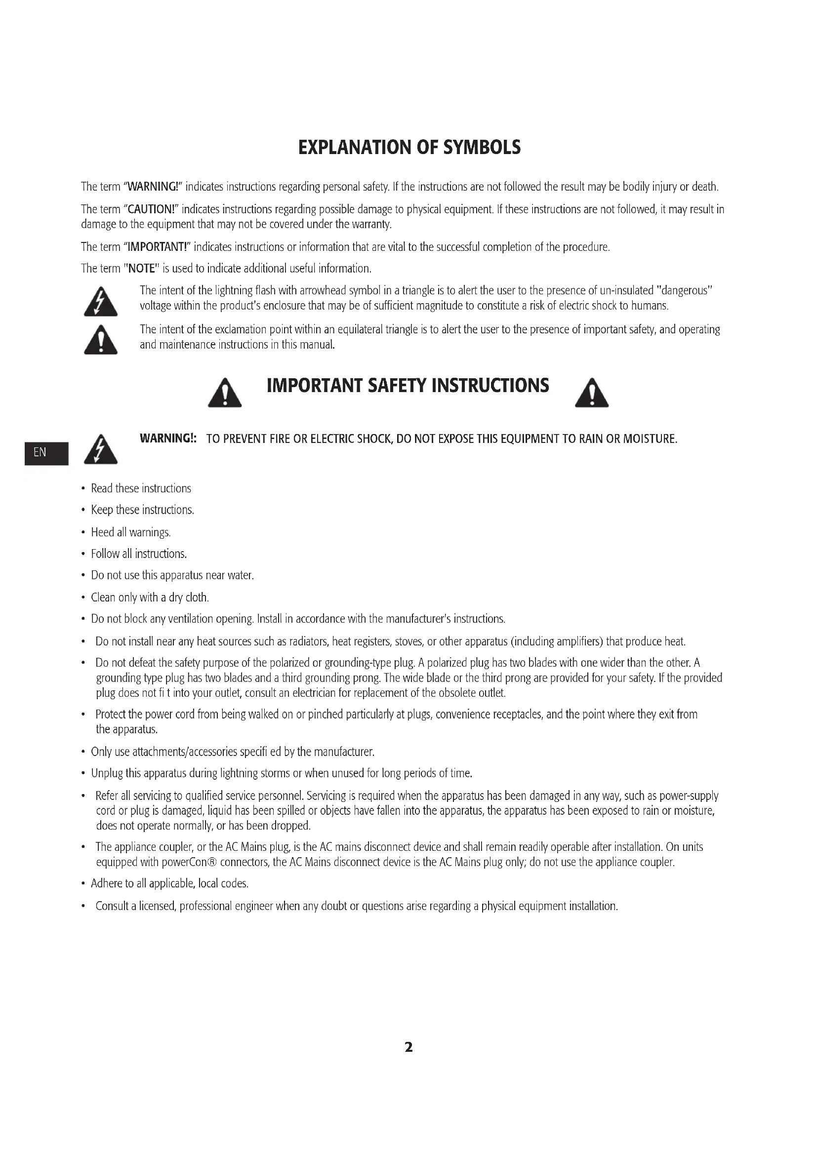
The term "WARNING!" indicates instructions regarding personal safety. If the instructions are not followed the result may be bodily injury or death.
The term "CAUTION!" indicates instructions regarding possible damage to physical equipment. If these instructions are not followed, it may result in damage to the equipment that may not be covered under the warranty.
The term "IMPORTANT!" indicates instructions or information that are vital to the successful completion of the procedure.
The term "NOTE" is used to indicate additional useful information.

The intent of the lightning flash with arrowhead symbol in a triangle is to alert the user to the presence of un-insulated "dangerous" voltage within the product's enclosure that may be of sufficient magnitude to constitute a risk of electric shock to humans.

The intent of the exclamation point within an equilateral triangle is to alert the user to the presence of important safety, and operating and maintenance instructions in this manual.

IMPORTANT SAFETY INSTRUCTIONS


WARNING!: TO PREVENT FIRE OR ELECTRIC SHOCK, DO NOT EXPOSE THIS EQUIPMENT TO RAIN OR MOISTURE.
- Read these instructions
- Keep these instructions.
- Heed all warnings.
- Follow all instructions.
- Do not use this apparatus near water.
- Clean only with a dry cloth.
- Do not block any ventilation opening. Install in accordance with the manufacturer's instructions.
- Do not install near any heat sources such as radiators, heat registers, stoves, or other apparatus (including amplifiers) that produce heat.
- Do not defeat the safety purpose of the polarized or grounding-type plug. A polarized plug has two blades with one wider than the other. A grounding type plug has two blades and a third grounding prong. The wide blade or the third prong are provided for your safety. If the provided plug does not fit into your outlet, consult an electrician for replacement of the obsolete outlet.
- Protect the power cord from being walked on or pinched particularly at plugs, convenience receptacles, and the point where they exit from the apparatus.
- Only use attachments/accessories specified by the manufacturer.
- Unplug this apparatus during lightning storms or when unused for long periods of time.
- Refer all servicing to qualified service personnel. Servicing is required when the apparatus has been damaged in any way, such as power-supply cord or plug is damaged, liquid has been spilled or objects have fallen into the apparatus, the apparatus has been exposed to rain or moisture, does not operate normally, or has been dropped.
- The appliance coupler, or the AC Mains plug, is the AC mains disconnect device and shall remain readily operable after installation. On units equipped with powerCon® connectors, the AC Mains disconnect device is the AC Mains plug only; do not use the appliance coupler.
- Adhere to all applicable, local codes.
- Consult a licensed, professional engineer when any doubt or questions arise regarding a physical equipment installation.
RoHS Statement
The CMX 300Va, CMX 500Va, CMX 800Va and CMX 2000Va amplifiers are in compliance with European Directive 2002/95/EC – Restriction of Hazardous Substances (RoHS).
The CMX 300Va, CMX 500Va, CMX 800Va and CMX 2000Va amplifiers are in compliance with "China RoHS" directives. The following chart is provided for product use in China and its territories:
| CMXa | ||||||
| 部件名称(Part Name) | 有毒有害物质或元素(Toxic or hazardous Substances and Elements) | |||||
| 铅(Pb) | 汞(Hg) | 镉(Cd) | 六价铬(Cr(vi)) | 多溴联苯(PBB) | 多溴二苯醚(PBDE) | |
| 电路板组件(PCB Assemblies) | X | O | X | O | O | O |
| 机壳装配件(Chassis Assemblies) | X | O | X | O | O | O |
| O: 表明这些有毒或有害物质在部件使用的同类材料中的含量是在 SJ/T11363_2006极限的要求之下。O: Indicates that this toxic or hazardous substance contained in all of the homogeneous materials for this part is below the limit requirement in SJ/T11363-2006.X: 表明这些有毒或有害物质在部件使用的同类材料中至少有一种而含量是在 SJ/T11363_2006极限的要求之上。X: Indicates that this toxic or hazardous substance contained in at least one of the homogeneous materials used for this part is above the limit requirement in SJ/T11363-2006. | ||||||
FCC Statement

NOTE: This equipment has been tested and found to comply with the limits for a Class B digital device, pursuant to Part 15 of the FCC Rules.
These limits are designed to provide reasonable protection against harmful interference in a residential installation. This equipment generates, uses and can radiate radio frequency energy and, if not installed and used in accordance with the instructions, may cause harmful interference to radio communications. However, there is no guarantee that interference will not occur in a particular installation. If this equipment does cause harmful interference to radio or television reception, which can be determined by turning the equipment off and on, the user is encouraged to try to correct the interference by one or more of the following measures:
- Reorient or relocate the receiving antenna.
- Increase the separation between the equipment and receiver.
- Connect the equipment into an outlet on a circuit different from that to which the receiver is connected.
- Consult the dealer or an experienced radio/TV technician for help.
Warranty (USA only; other countries, see your dealer or distributor)
QSC Audio Products 3 Year Limited Warranty
QSC Audio Products, LLC ("QSC") guarantees its products to be free from defective material and/or workmanship and will replace defective parts and repair malfunctioning products under this warranty when the defect occurs under normal installation and use, provided the unit is returned to our factory, one of our authorized service stations or an authorized QSC International Distributor via pre-paid transportation with a copy of proof of purchase (i.e., sales receipt). This warranty provides that the examination of the return product must indicate, in our judgment, a manufacturing defect. This warranty does not extend to any product which has been subjected to misuse, neglect, accident, improper installation, or where the date code has been removed or defaced. QSC shall not be liable for incidental and/or consequential damages. This warranty gives you specific legal rights. This limited warranty is freely transferable during the term of the warranty period. The warranty on QSC products is NOT VALID if the products have been purchased from an unauthorized dealer/online e-tailer, or if the original factory serial number has been removed, defaced, or replaced in any way. Damage to, or loss of any software or data residing on the product is not covered. When providing repair or replacement service, QSC will use reasonable efforts to reinstall the product's original software configuration and subsequent update releases, but will not provide any recovery or transfer of software or data contained on the serviced unit not originally included in the product.
Customers may have additional rights, which vary from state to state or from country to country. In the event that a provision of this limited warranty is void, prohibited or superseded by local laws, the remaining provisions shall remain in effect.
The QSC limited warranty is valid for a period of three (3) years from date of purchase in the United States and many (but not all) other countries.
For QSC warranty information in countries other than the United States, contact your authorized QSC international distributor. A list of QSC International distributors is available at www.qsc.com.
To register your QSC product online, go to www.qsc.com and select "Product Registration". Other questions regarding this warranty can be answered by calling, e-mailing or contacting your authorized QSC distributor.
Phone: 1-800-854-4079 within US and Canada, +1-714-754-6175 international, Email: warranty@qsc.com, Website: www.qsc.com.
Introduction
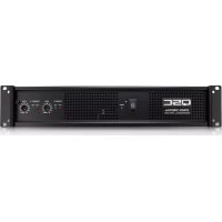
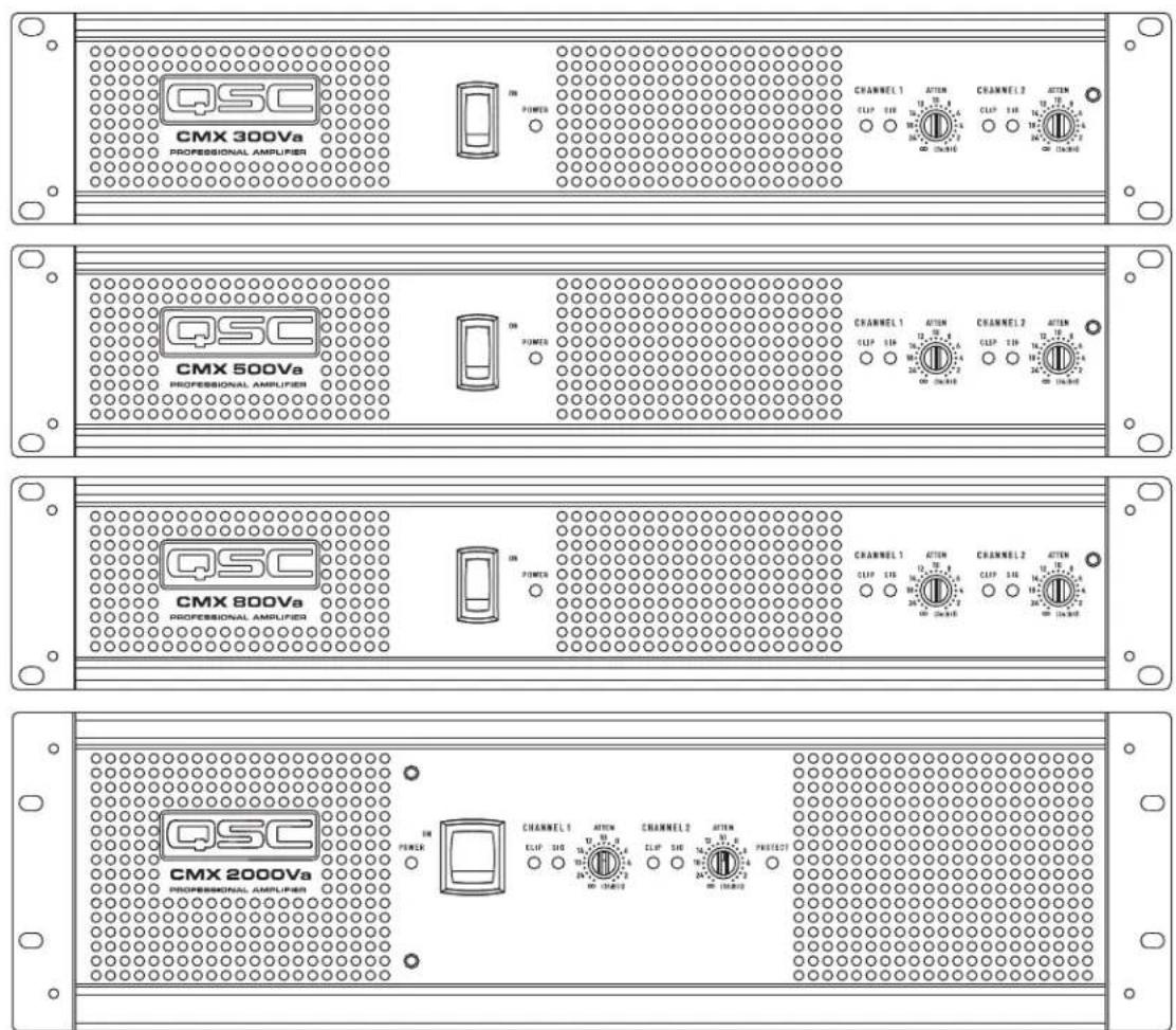
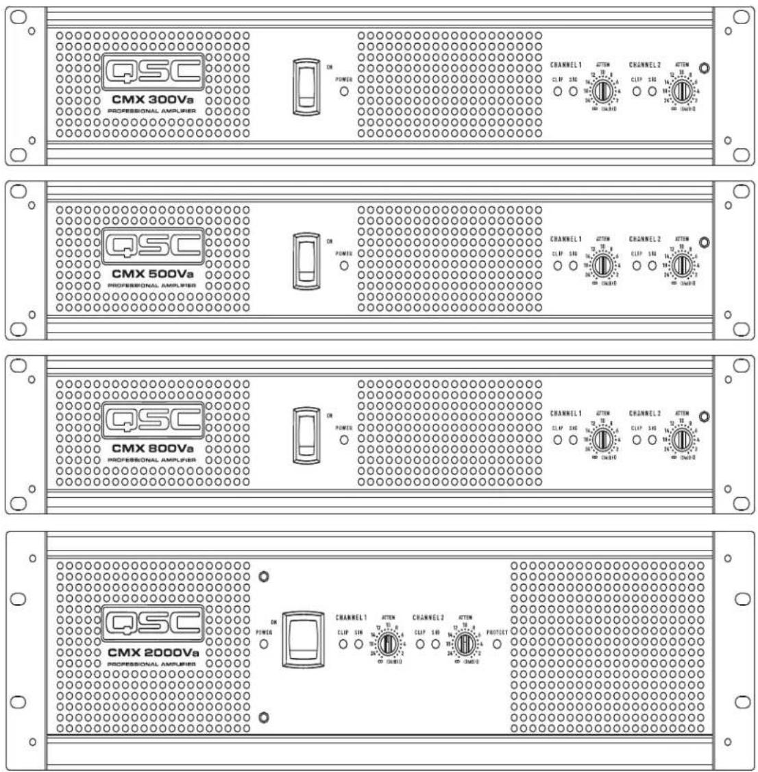
These rugged, fan-cooled, 2-channel, 2RU/3RU amplifiers provide high-value performance and power in a strong, compact chassis. The series comprises four models: the CMX 300Va, CMX 500Va, CMX 800Va and CMX 2000Va.
CMX 300Va CMX 500Va CMX 800Va CMX 2000Va
| Stereo Mode (both channels driven) | ||||
| 8Ω/ FTC 20 Hz - 20 kHz / 0.1% THD | 185 W | 260 W | 450 W | 1050 W |
| 8Ω/ EIA 1 KHZ / 0.1% THD | 200 W | 300 W | 500 W | 1100 W |
| 4Ω/ FTC 20 Hz - 20 KHZ / 0.1% THD | 280W | 400 W | 650 W | 1600 W |
| 4Ω/ EIA 1 KHZ / 0.5% THD | 300 W | 500 W | 800 W | |
| 4Ω/ EIA 1 KHZ / 1% THD | 2000 W | |||
| 2Ω/ EIA 1 KHZ / 1% THD | 430 W | 700 W | 1200 W | 2500 W |
| 70 V - Direct drive / EIA 1 kHz / 1% THD | - | - | 400 W | 2500 W |
| 100 V - Direct drive / EIA 1 kHz / 1% THD | 1000 W | |||
| Bridge Mono Mode | ||||
| 8Ω/ FTC 20 Hz - 20 kHz / 0.1%THD | 530 W | 800 W | 1300 W | 3200 W |
| 8Ω/ EIA 1 kHz / 0.1%THD | 600 W | 900 W | 1500 W | 3600 W |
| 4Ω/ EIA 1 kHz / 1%THD | 830 W | 1400 W | 2400 W | 5000 W |
| 70 V - Direct drive / EIA 1 kHz / 1% THD | 600 W | 1200 W | 2000 W | |
| 100 V - Direct drive / EIA 1 kHz / 1% THD | - | 600 W | 2300 W | 3600 W |
| 140 V - Direct drive / EIA 1 kHz / 1% THD | 5000 W | |||
- Table 1 -
Features
- Independent, user-defeatable clip limiters
- Fully selectable low-frequency fi ltering; choice of 30 or 50 Hz roll-off
- Stereo (dual-channel), parallel-input, or Bridge Mono operating modes
-
Balanced inputs – XLR, 1/4" (6.3 mm) TRS, and barrier strip
-
Pluggable terminal block and NL4 outputs
• 21 detent gain knobs - Front panel LED indicators for signal and clip and power
• Attenuation control security plate
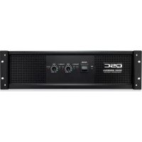
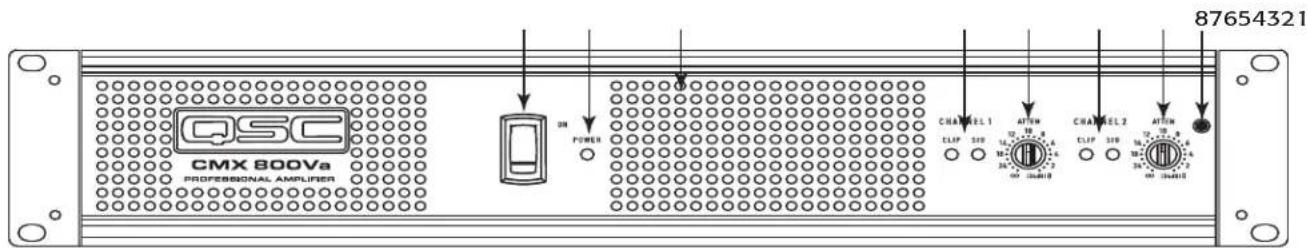
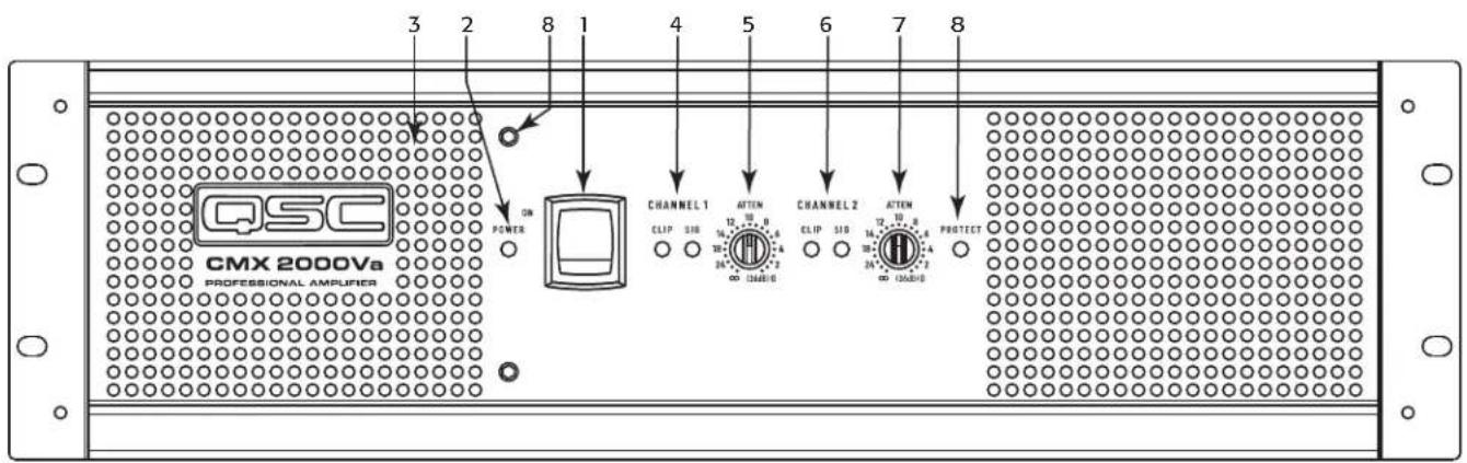
Front Panel
- Power switch
- Power indicator LED
- Cooling vents
-
Clip and Signal indicator LEDs, (Channel 1)
-
Attenuation controls (Channel 1)
- Clip and Signal indicator LEDs, (Channel 2)
- Attenuation control (Channel 2)
- Lockout plate retention screw
text_image
QSC CMX 800Va PROFESSIONAL AMPLIENER 87654321- Figure 1 -
text_image
QSC CMX 2000Va PROFESSIONAL AMPLIFIER POWER CHANNEL 1 ATTEN CHANNEL 2 ATTEN PROTECT 3 2 8 1 4 5 6 7 8 CLIP SID 12, 10, 8 CLIP SID 14, 10, 8 12, 10, 8 14, 10, 8 12, 10, 8 14, 10, 8 12, 10, 8 14, 10, 8 12, 10, 8 14, 10, 8 12, 10, 8 14, 10, 8 12, 10, 7 14, 10, 7 12, 10, 7 14, 10, 7 12, 10, 7 14, 10, 7 12, 10, 7 14, 10, 7 12, 10, 7 14, 10, 7 12, 10, 7 14, 10, 6 12, 10, 6 14, 10, 6 12, 10, 6 14, 10, 6 12, 10, 6 14, 10, 6 12, 10, 6 14, 10, 6 12, 10, 6 14, 10, 6 12, 10, 5 14, 10, 5 12, 10, 5 14, 10, 5 12, 10, 5 14, 10, 5 12, 10, 5 14, 10, 5 12, 10, 5 14, 10, 5 12, 10, 5 14, 10, 4 12, 10, 4 14, 10, 4 12, 10, 4 14, 10, 4 12, 10, 4 14, 10, 4 12, 10, 4 14, 10, 4 12, 10, 4 14, 10, 4 12, 10, 3 14, 10, 3 12, 10, 3 14, 10, 3 12, 10, 3 14, 10, 3 12, 10, 3 PROTECT- Figure 2 -
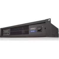
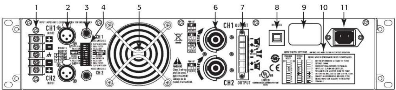
Back Panel
- Barrier strip input
- XLR inputs, Channels 1 and 2
- TRS inputs, Channels 1 & 2
- Configuration dip switches
- Fan
-
NL4 output, Channel 1 and 2
-
Terminal block connector outputs, Channels 1 and 2
- Circuit Breaker
- Serial number label
- Configuration switch chart
- IEC power inlet (power cord connector)
text_image
1 2 3 4 5 6 7 8 9 10 11 INPUT IMPROACH 200 MPV MOUNTED TIN IMPROACHS CH1 INPUT PINFUTS FILTER UP MOMICS FILTER UP FILTER OUT MOMICS FILTER SWITCHES CH2 WARNING Class 2 wiring shall be used. AVENTISSEMENT Cable de la Class 2 sera utiliz. PINFUT PINFUT CH1 OUTPUT CH2 OUTPUT LISTED COMMERCIAL ANDIC SYSTEM DATA MODE SWITCH SETTINGS - AMP INCLUDED NAME TO THE RED OUT OUTPUT INFORMATION FINAL ON: RIGHT ON: 50° RIGHT ON: 50° RIGHT ON: 50° RIGHT ON: 50° RIGHT ON: 50° RIGHT ON: 50° RIGHT ON: 50° RIGHT ON: 50° RIGHT ON: 50° RIGHT ON: 50° RIGHT ON: 50° RIGHT ON: 50° RIGHT ON: 50° RIGHT ON: SELECT SWITCHING INPUTS OR INPUTS FOR PAINING SELECT SWITCHING INPUTS OR INPUTS FOR PAINING SELECT SWITCHING INPUTS OR INPUTS FOR SWITCHING SELECT SWITCHING INPUTS OR INPUTS FOR SWITCHING SELECT SWITCHING INPUTS OR INPUTS FOR SWITCHING SELECT SWITCHING INPUTS OR INPUTS FOR SWITCHING SELECT SWITCHING INPUTS OR INPUTS FOR SWITCHING SELECT SWITCHING INPUTS OR INPUTS FOR SWITCHING- Figure 3 -
Features and Setup
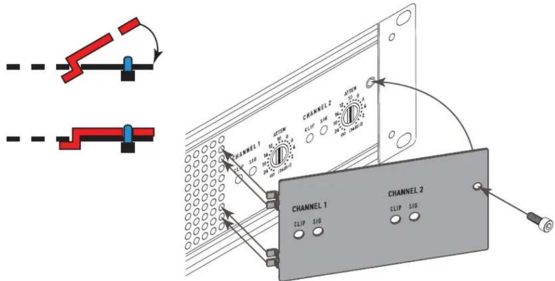
Attenuation Control Security Plate
The Attenuation control security plate (− Figure 4) provides protection against accidentally adjusting the Attenuation controls on the amplifier face.
Attach the plate, after making final adjustments to the Attenuation controls, by sliding the tabs into the installation slots. Secure in place with the attachment screw.
text_image
CHANNEL 1 SIG 24 14 24 32 4 5 6 7 8 9 10 11 12 13 14 15 16 17 18 19 20 21 22 23 24 25 26 27 28 29 30 31 32 33 34 35 36 37 38 39 40 41 42 43 44 45 46 47 48 49 50 51 52 53 54 55 56 57 58 59 60 61 62 63 64 65 66 67 68 69 70 71 72 73 74 75 76 77 78 79 80- Figure 4 -
Setting the Mode Switches
The CMXa has mode switches for STEREO, PARALLEL INPUTS, or BRIDGE MONO modes. Each channel has independent clip limiting and low frequency fi ltering.
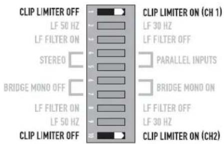
Clip Limiter
What it is
When the audio signal drives the amplifi er's output circuit beyond its power capability, it clips, fl attening the peaks of the waveform. The clip limiter detects this and reduces the gain to minimize the amount of overdrive. To preserve as much of the program dynamics as possible, limiting reduces the average program level until peaks barely clip.
Each channel has its own clip limiter, and you can switch it on or off independently, as shown in – Figure 5.
text_image
CLIP LIMITER OFF LF 50 HZ LF FILTER ON STEREO BRIDGE MONO OFF LF FILTER ON LF 50 HZ CLIP LIMITER OFF CLIP LIMITER ON (CH 1) LF 30 HZ LF FILTER OFF PARALLEL INPUTS BRIDGE MONO ON LF FILTER OFF LF 30 HZ CLIP LIMITER ON (CH2)- Figure 5 -
When to use it (or not)
When driving full-range speakers, clip limiting reduces high-frequency distortion caused by bass overloads. It also protects higher frequency drivers from excess overdrive and harsh clipping harmonics.
When driving subwoofers, some users let the amplifier clip without limiting because it gives extra "punch" to kick drums and similar sounds.

CAUTION: In bi-amp systems, excessive limiting will affect the frequency balance.
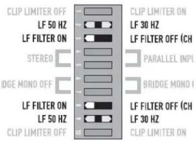
Input Low-Frequency Filter
What it is
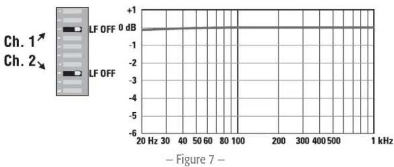
The low-frequency (LF) filter rolls off signals below either 30 Hz or 50 Hz (— Figure 8 and — Figure 9). This improves bass performance by limiting sub-audio cone motion, making more power available for the speakers' rated frequency range.
The filter settings for each channel are controlled individually through the DIP switch settings shown in – Figure 6. When the filter is turned off (– Figure 7), a 5 Hz roll off protects against DC or deep sub-audio inputs.
text_image
CLIP LIMITER OFF LF 50 HZ LF FILTER ON STEREO IDGE MONO OFF LF FILTER ON LF 50 HZ CLIP LIMITER OFF CLIP LIMITER ON LF 30 HZ LF FILTER OFF (CH) PARALLEL INPL BRIDGE MONO I LF FILTER OFF (CH) LF 30 HZ CLIP LIMITER ON- Figure 6 -
When to use it (or not)
As a rule, your speakers will sound better with proper fi Itering. Unless you already have fi Itering in a preceding device, match the setting to the low frequency rating of your speakers. Vented (bass refl ex, ported, etc.) speakers are especially sensitive to cone over-excursion at frequencies below their rated limit.
The 50 Hz fi liter works well with most compact full-range speakers, and has a slight boost at 100 Hz for greater fullness. The 30 Hz fi liter is intended for subwoofers and large full-range cabinets. The "off" position should be used only for applications such as studio playback monitoring, where you need to know if there are unwanted sub-audio signals present in your mix.
line
| Frequency | LF OFF (dB) | | --------- | ----------- | | 20 Hz | +1 | | 30 Hz | +1 | | 40 Hz | +1 | | 50 Hz | +1 | | 60 Hz | +1 | | 70 Hz | +1 | | 80 Hz | +1 | | 90 Hz | +1 | | 100 Hz | +1 | | 200 Hz | +1 | | 300 Hz | +1 | | 400 Hz | +1 | | 500 Hz | +1 | | 1 kHz | +1 |
line
| Frequency | Amplitude (dB) | | --------- | -------------- | | 20 Hz | -6 | | 30 Hz | -5 | | 40 Hz | -4 | | 50 Hz | -2 | | 60 Hz | -1 | | 70 Hz | 0 | | 80 Hz | 0.5 | | 90 Hz | 0.8 | | 100 Hz | 0.9 | | 200 Hz | 0.8 | | 300 Hz | 0.7 | | 400 Hz | 0.6 | | 500 Hz | 0.5 | | 1 kHz | 0.4 |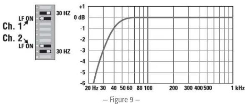
line
| Frequency | Amplitude (dB) | | --------- | -------------- | | 20 Hz | -6 | | 30 Hz | -3 | | 40 Hz | -1 | | 50 Hz | 0 | | 60 Hz | 0 | | 80 Hz | 0 | | 100 Hz | 0 | | 200 Hz | 0 | | 300 Hz | 0 | | 400 Hz | 0 | | 500 Hz | 0 | | 1 kHz | 0 |Parallel Input Mode
What it is
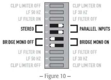
The Parallel Input switches let you operate the amplifi er in Parallel mode, delivering the same signal to both channels without using a Y cable. Each channel drives its own speaker load, with independent gain, fi ltering, and clip limiting.
Set switch positions 4 and 5 to "PARALLEL INPUTS" to couple the inputs together (— Figure 10). Turn the switches to "STEREO" for stereo, bi-amping, or other 2-channel modes.
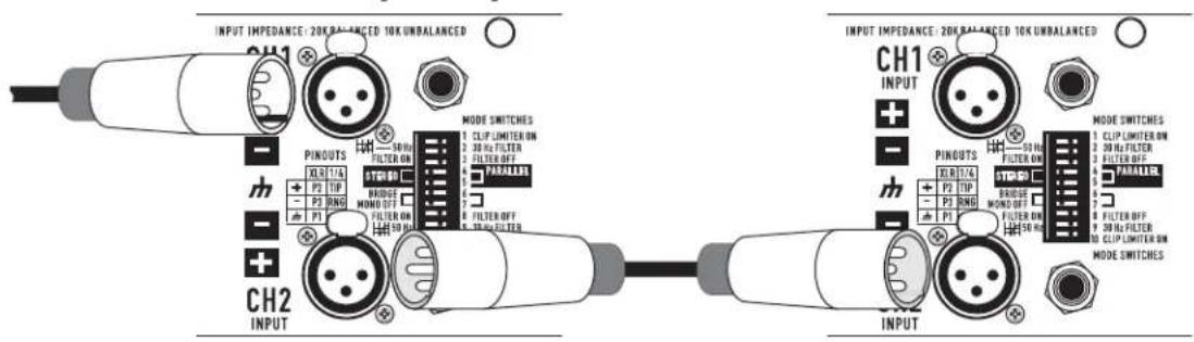
With the inputs in parallel, you can use the other set of input connectors to carry the signal to other amps (- Figure 11). This is often called a "daisy-chain."
text_image
CLIP LIMITER OFF LF 50 HZ LF FILTER ON STEREO BRIDGE MONO OFF LF FILTER ON LF 50 HZ CLIP LIMITER OFF CLIP LIMITER ON LF 30 HZ LF FILTER OFF PARALLEL INPUTS BRIDGE MONO ON LF FILTER OFF LF 30 HZ CLIP LIMITER ON Figure 10 -When to use it
Use the Parallel mode when driving two speakers with one input signal (Parallel mode) while keeping separate control of both channels' gain, filtering, and limiting. Use Parallel mode and Bridge Mono mode to patch the signal to additional amplifiers through the extra input jacks.

NOTE: If you're using a balanced signal, use only balanced patch cables; even one unbalanced cable will unbalance the entire signal chain, possibly causing hum.
Amp 1 Amp 2
text_image
INPUT IMPEDANCE: 20K BALANCED 10K UNBALANCED CH1 PINDUTS XLR TIA + P2 TIP - P3 RNG + P1 MODE SWITCHES 50 Hz FILTER ON 30 Hz FILTER 20 Hz Filter PARALLER 6 FILTER OFF 50 Hz FILTER CH2 INPUT INPUT IMPEDANCE: 20K BALANCED 10K UNBALANCED CH1 PINDUTS XLR TIA + P2 TIP - P3 RNG + P1 50 Hz FILTER ON 30 Hz FILTER OFF 20 Hz FILTER 20 Hz Filter PARALLER 6 FILTER OFF 50 Hz FILTER MODE SWITCHES 1 CLIP LIMITER ON 2 30 Hz FILTER 3 FILTER OFF 4 FILTER OFF 5 CLIP LIMITER ON MODE SWITCHES- Figure 11 -

NOTE: Turn off the "Parallel Inputs" switches when feeding the amp two separate signals.
Bridge Mono Mode
What it is
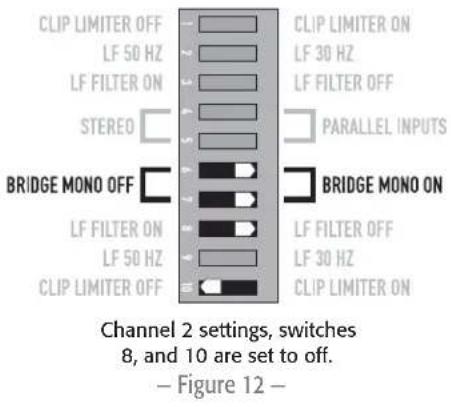
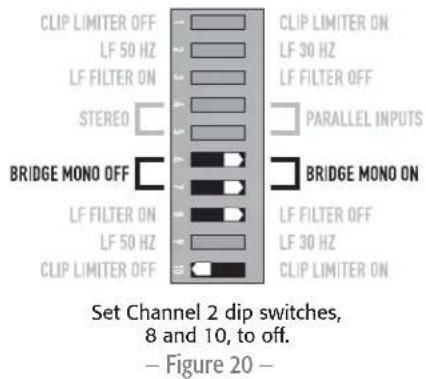
Bridge Mono mode combines the power of both amp channels into one speaker, resulting in twice the voltage swing, four times the peak power, and approximately three times the sustained power of a single channel. This mode uses Channel 1's input, attenuation control, input filter, and clip limiter; Channel 2's dip switch settings should be in the OFF position, the attenuation control should be at maximum attenuation (– Figure 12 and – Figure 13).
When to use it (or not)
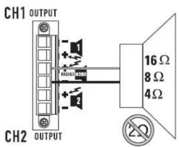
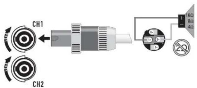
Use Bridge Mono mode to deliver the power of both channels to a single 8 or 4Ω load. Set switch positions 6 and 7 to BRIDGE MONO ON (– Figure 12). Use Channel 1's inputs, and connect the loudspeaker as shown in – Figure 14 or – Figure 15).
Bridge Mono Precautions
This mode puts a high demand on the amplifier and speaker, Excessive clipping may cause protective muting or speaker damage. Be sure the speaker has a sufficient power rating.

WARNING!: Output voltages greater than 100 volts RMS are available between the bridged terminals of the CMXa. CLASS 3 wiring methods (NEC 1999), as specified in accordance with national and local codes, must be used to connect the speaker.
text_image
CLIP LIMITER OFF LF 50 HZ LF FILTER ON STEREO BRIDGE MONO OFF LF FILTER ON LF 50 HZ CLIP LIMITER OFF CLIP LIMITER ON LF 30 HZ LF FILTER OFF PARALLEL INPUTS BRIDGE MONO ON LF FILTER OFF LF 30 HZ CLIP LIMITER ON Channel 2 settings, switches 8, and 10 are set to off. — Figure 12 —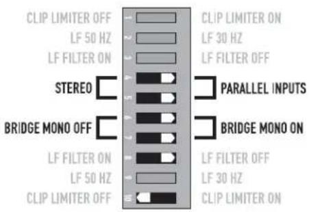
text_image
CLIP LIMITER OFF LF 50 HZ LF FILTER ON STEREO BRIDGE MONO OFF LF FILTER ON LF 50 HZ CLIP LIMITER OFF CLIP LIMITER ON LF 30 HZ LF FILTER OFF PARALLEL INPUTS BRIDGE MONO ON LF FILTER OFF LF 30 HZ CLIP LIMITER ONTo patch the signal to additional amplifiers, use the parallel input switches described under Parallel Input Mode. — Figure 13 —
text_image
CH1 OUTPUT CH2 OUTPUT 1 2 BRIDGE NORD 16 Ω 8 Ω 4 Ω 2Ω- Figure 14 -
text_image
CH1 CH2 16Ω 8Ω 4Ω- Figure 15 -
The Difference Between Modes
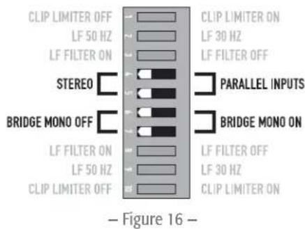
Stereo Mode
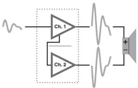
Stereo mode is the typical way of using the amplifier. Each channel is fully independent. Separate signals connect at the inputs, the attenuation knobs control their respective channels, and separate speakers connect to each output. The dip switches are set as shown in — Figure 16, a schematic illustration in — Figure 17.
Examples:
- Two-channel (stereo) playback.
- Two independent mono signals, such as main and monitor mixes.
- Bi-amped operation, with the low frequencies in Channel 1 and the highs in Channel 2.
text_image
CLIP LIMITER OFF LF 50 HZ LF FILTER ON STEREO BRIDGE MONO OFF LF FILTER ON LF 50 HZ CLIP LIMITER OFF CLIP LIMITER ON LF 30 HZ LF FILTER OFF PARALLEL INPUTS BRIDGE MONO ON LF FILTER OFF LF 30 HZ CLIP LIMITER ON Figure 16 -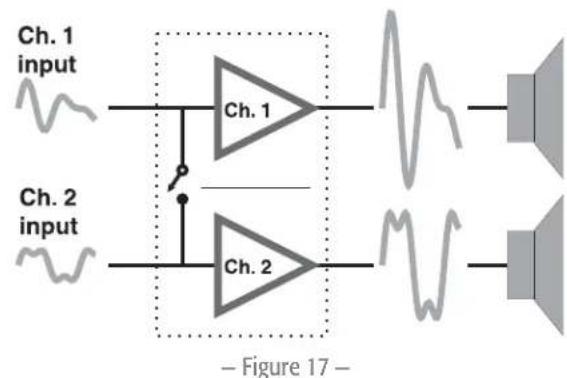
flowchart
graph LR
    A["Ch. 1 input"] --> B["Ch. 1"]
    C["Ch. 2 input"] --> D["Ch. 2"]
    B --> E["Waveform with high-frequency oscillations"]
    D --> F["Waveform with low-frequency oscillations"]
    style A fill:#f9f,stroke:#333
    style C fill:#f9f,stroke:#333
    style B fill:#ccf,stroke:#333
    style D fill:#ccf,stroke:#333
    style E fill:#dfd,stroke:#333
    style F fill:#dfd,stroke:#333
    subgraph Figure 17
        B --> E
        D --> F
    end
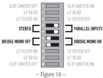
Parallel Input Mode
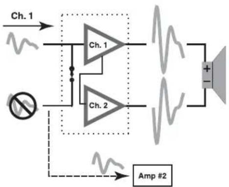
This mode is similar to the Stereo mode, except that the inputs for Channel 1 and Channel 2 are internally connected together. A signal into Channel 1 jack drives both channels directly (— Figure 18). Use Channel 1 Input, do not connect different sources to both channels. Each channel's attenuation control still functions as usual, and each channel feeds its own speaker load. The dip switches are set as shown in — Figure 19.
In Parallel mode, you can patch the input signal on to additional amplifiers by using any of the remaining input jacks. See Ch. 2 in – Figure 18.
Example:
One mono signal driving both channels, with independent attenuation control for each speaker system.
text_image
CLIP LIMITER OFF LF 50 HZ LF FILTER ON STEREO BRIDGE MONO OFF LF FILTER ON LF 50 HZ CLIP LIMITER OFF CLIP LIMITER ON LF 30 HZ LF FILTER OFF PARALLEL INPUTS BRIDGE MONO ON LF FILTER OFF LF 30 HZ CLIP LIMITER ON Figure 18 -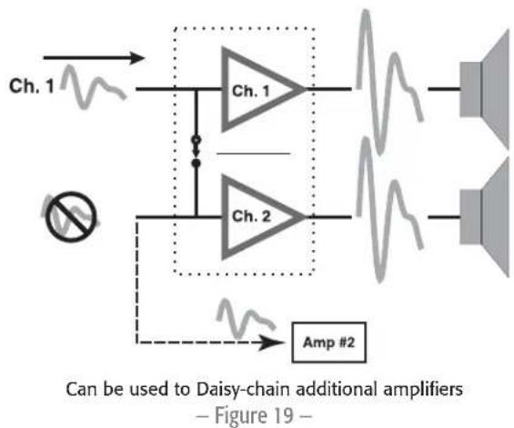
flowchart
graph TD
    A["Ch. 1"] --> B["Ch. 1"]
    C["Ch. 2"] --> D["Ch. 1"]
    E["Amp #2"] --> F["Speaker"]
    style A fill:#f9f,stroke:#333
    style C fill:#f9f,stroke:#333
    style E fill:#ccf,stroke:#333
    note right of C: No noise symbol
    note bottom of E: Can be used to Daisy-chain additional amplifiers — Figure 19 —
Bridge Mono Mode
This mode combines the full power capabilities of both channels into a single speaker system. The amplifi er internally re-confi gures so that both channels operate as a unit. This delivers double the output voltage, resulting in four times the peak power and three times the sustained power into a single 8 or 4Ω speaker load. The Bridge Mono mode section on page 10 describes the special loudspeaker connection used.
Examples:
- Driving a single 8 speaker with the combined 4 power of both channels.
- Driving a single 4 speaker with the combined 2 power of both channels.
Precautions:
- Bridge Mono mode makes it possible to drive thousands of watts into a single speaker. AC current consumption will usually be higher. Avoid excessive signal level, and make sure the wiring and speaker can handle the power.
- If the load is 4Ω or less and prolonged overloads occur, the amplifier will probably mute for several seconds during peaks, and the circuit breaker may trip.
- Do not use 2 loads.
- Ensure Channel 2 dip switches are set to off (– Figure 20), and Channel 2 attenuation control is set to maximum attenuation.
text_image
CLIP LIMITER OFF LF 50 HZ LF FILTER ON STEREO BRIDGE MONO OFF LF FILTER ON LF 50 HZ CLIP LIMITER OFF CLIP LIMITER ON LF 30 HZ LF FILTER OFF PARALLEL INPUTS BRIDGE MONO ON LF FILTER OFF LF 30 HZ CLIP LIMITER ON Set Channel 2 dip switches, 8 and 10, to off. — Figure 20 —
NOTE: See the additional Bridge Mono precautions on page 10.
Distributed Constant Voltage Outputs
Please refer to the above section on Bridge Mono mode for proper setup configuration.
70/100 Volt Operation:
- The CMX 300Va and 500Va must be configured for Bridge Mono mode for 70 Volt operation.
- The CMX 800Va and CMX 2000Va can operate in 70 Volt operation in Stereo mode or Bridge Mono mode.
- The CMX 500Va and CMX 800Va must be configured for Bridge Mono mode for 100 Volt operation. Please refer to the Bridge Mono mode section for proper setup configuration.
The CMX 2000Va can operate in 70 Volt or 100 Volt operation in STEREO mode or BRIDGE MONO mode..
CMX 300Va CMX 500Va CMX 800Va CMX 2000Va
| Stereo Mode (Both Channels Driven) | ||||
| 70 Volt -- 400 W 2500 W | ||||
| 100 Volt --- | 1000 W | |||
| Bridge Mono Mode | ||||
| 70 Volt | 600 W | 1200 W | 2000 W | 5000 W |
| 100 Volt - | 600 W | 2300 W | 3600 W | |
- Table 2 -
flowchart
graph LR
    A["Input Signal"] --> B["Ch. 1"]
    A --> C["Ch. 2"]
    B --> D["Output Signal"]
    C --> D
    D --> E["Speaker"]
Channel 1 Input, Channel 2 Not Used
- Figure 21 -
flowchart
graph TD
    A["Ch. 1"] --> B["Ch. 1"]
    C["No"] --> D["Ch. 2"]
    B --> E["+"]
    D --> F["Amp #2"]
    E --> G["Speaker"]
    F --> G
    style A fill:#f9f,stroke:#333
    style C fill:#ccf,stroke:#333
    style B fill:#cfc,stroke:#333
    style D fill:#fcc,stroke:#333
    style E fill:#ffc,stroke:#333
    style F fill:#cff,stroke:#333
Channel 2 Can Be Used to Daisy-chain to Other Amplifiers.
- Figure 22 -
Installation
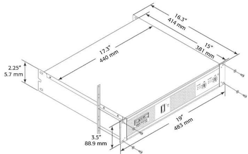
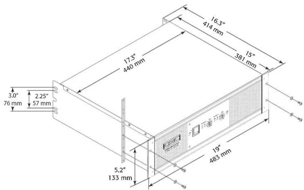
Rack mounting of the amplifier is optional.
Use four screws and washers when mounting the amplifier to the front rack rails.
Support the amp at the rear also, especially in mobile and touring use; rear rack mounting ear kits are available from QSC's technical services department or by special order from your dealer or distributor. Use the dimensions in – Figure 23 and – Figure 24 for planning.
text_image
16.3" 414 mm 15" 381 mm 17.3" 440 mm 2.25" 5.7 mm 3.5" 88.9 mm 19" 483 mm- Figure 23 -
text_image
3.0" 76 mm 2.25" 57 mm 17.3" 440 mm 16.3" 414 mm 15" 381 mm 19" 483 mm 5.2" 133 mm φ-α4 φ-α4- Figure 24 -
Connections
Inputs
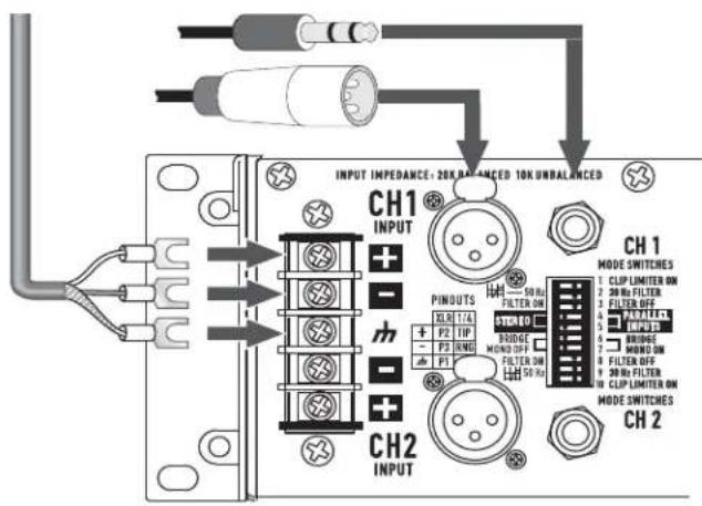
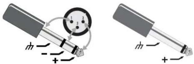
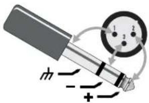
Each channel has active balanced XLR and 14 " (6.3 mm) inputs wired in parallel (- Figure 25). The input impedance is 20 kΩ balanced, 10 kΩ unbalanced.
Balanced signals are less prone to AC hum, but unbalanced signals can be suitable for short cable runs. The signal source's output impedance should be less than 600Ω to avoid high frequency loss in long cables.
Balanced Inputs
Use the XLR or 1/4" (6.3 mm) TRS input jacks, or the barrier strip (- Figure 26 through - Figure 28).
text_image
INPUT IMPEDANCE - 20K UNBALANCED 10K UNBALANCED CH1 INPUT CH2 INPUT PINDUTS 50 Hz FILTER ON STUDIO P2 TIP - P3 RWD BRIDGE MUND OFF FILTER ON 50 Hz CH1 MODE SWITCHES 1 CLIP LIMITER ON 2 20 Hz FILTER 3 FILTER OFF 4 METER 5 INPUTS 6 BRIDGE 7 HAND ON 8 FILTER OFF 9 30 Hz FILTER 10 CLIP LIMITER ON MODE SWITCHES CH2- Figure 25 -
Unbalanced Inputs
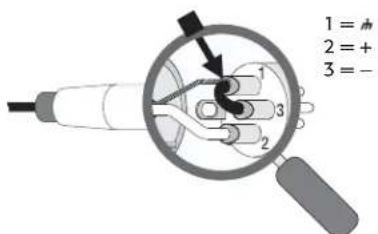
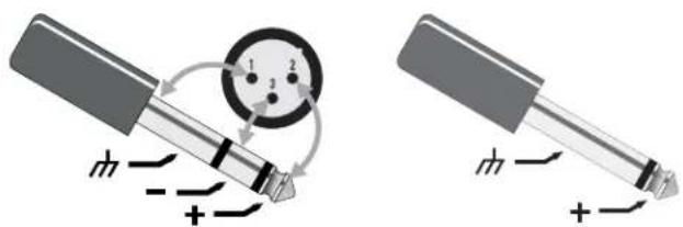
- Connect the unused side (Pin 3) of the balanced input to ground (Pin 1), as shown in – Figure 26.
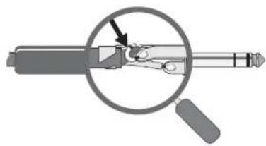
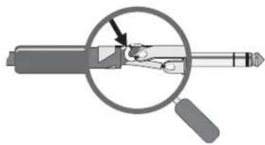
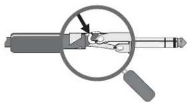
- A tip-sleeve 14 " (6.3 mm) connector will correctly terminate the unused side of the input as shown in - Figure 27.
- For Stereo operation, use the inputs for both Channel 1 and Channel 2. For Parallel or Bridge Mono operation, use the Channel 1 input.
- See the section on operating modes for more information. To patch the audio signal to other amps (Parallel and Bridge Mono modes only), see the instructions for using Parallel Inputs on page 9.
text_image
1 = + 2 = + 3 = -XLR unbalanced Jumper pin 1 to pin 3 — Figure 26 —
natural_image
Diagram of a mechanical device with a magnified inset showing internal components (no text or symbols)TRS unbalanced No modification needed – Figure 27 –
text_image
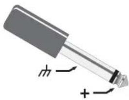
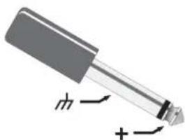
Diagram illustrating a mechanical or electrical setup with labeled components and directional arrows, possibly indicating motion or force.Balanced Unbalanced
- Figure 28 -
Outputs
NL4 Outputs
CMXa amplifiers offer a choice of output connections, with two NL4 jacks and a Terminal Block connector.
The NL4 connector is designed specially for high-power speaker connections. It locks in place, prevents shock hazard, and assures the correct polarity.
The upper NL4 jack has both Channel 1 and Channel 2 outputs, so it is especially useful for Parallel, bi-amp, or Bridge Mono mode operation (see Bridge Mono mode operating precautions on page 10). The other NL4 carries only the output from Channel 2.
For easier insertion, use the NL4FC connectors with quick-lock thumb latches (Not shown).
Speaker Cabling
Larger wire sizes and shorter lengths minimize both loss of power and degradation of damping factor. Do not place speaker cables next to input wiring.

WARNING!: To prevent electric shock, do not operate the amplifier with any of the conductor portion of the speaker wire exposed.
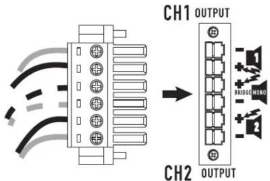
Terminal Block Connector
The terminal block connector requires the following assembly.
- Strip the wires to 7 \~ 8 mm.
- Insert the wires into the male part of the connector according to the Mode you are using. See below.
- Use a fl at-tip screwdriver to secure the wires. Tighten the screws to 6 in.-lbs.
- Insert the plug into the receptacle on the amplifier.
- Use a flat-tip screwdriver to secure the connector. Tighten the screws to 6 in.-lbs.
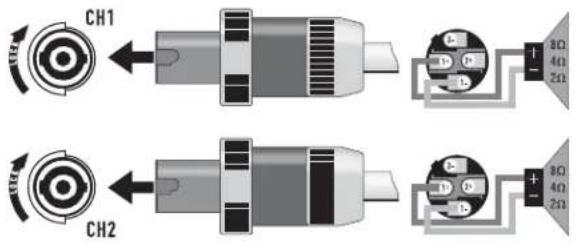
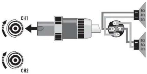
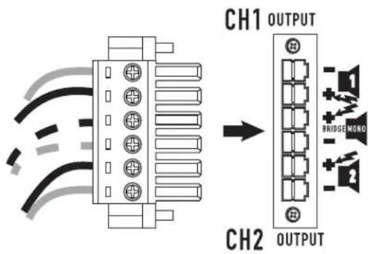
Stereo and Parallel Mode: Connect the wires as shown in — Figure 30, or as shown by the solid wires in — Figure 32.
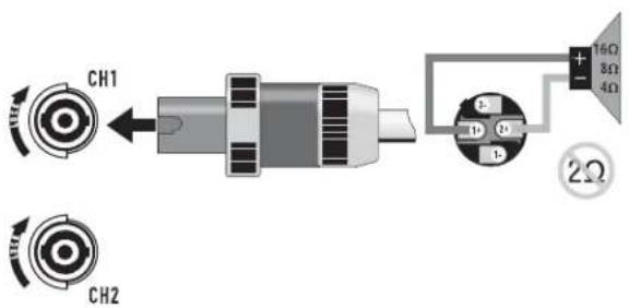
Bridge Mode: Connect the wires as shown in – Figure 31, or as shown by the dashed wires in – Figure 32.
Terminal Block Connector Wiring UL IEC
| Wire range - 6 mm | 2 | |
| Solid wire (AWG) 28 – 10 - | ||
| Stranded wire (AWG/mm ^2 ) 28 – 10 - | ||
| Torque (lb.-in.) | 6 | - |
| Wire strip length | 7 – 8 mm | - |
- Table 3 -
text_image
CH1 CH2Stereo, Bi-amp, or Parallel Mode — Figure 29 —
text_image
CH1 CH2 8Ω 4Ω 2Ω 8Ω 4Ω 2ΩStereo, Bi-amp, or Parallel Mode — Figure 30 —
text_image
CH1 CH2 16Ω 8Ω 4Ω 2ΩBridge Mono Mode — Figure 31 —
text_image
CH1 OUTPUT CH2 OUTPUT BRIDGE MONO- Figure 32 -
Operation
AC Power Switch (AC Mains)
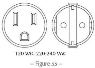
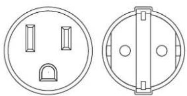
Make sure you connect the amplifi er to the correct AC line voltage, as shown on the serial number label. Connecting to the wrong line voltage is dangerous and may damage the amplifier (— Figure 33).
Before applying power, check all connections and turn the attenuation controls fully counter clockwise to maximum attenuation.
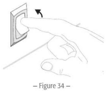
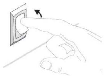
One second of muting is normal when the amp is turned on or off (- Figure 34).
text_image
120 VAC 220-240 VAC — Figure 33 —Attenuation Controls
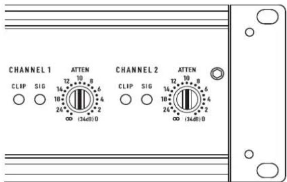
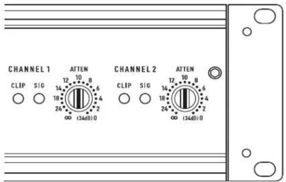
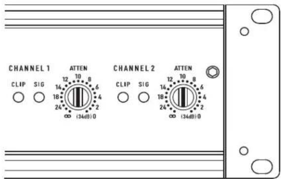
The controls are marked with a scale indicating attenuation. Maximum attenuation is fully counter clockwise, minimum attenuation is fully clockwise. he Attenuation controls are marked in numeric increments from to 0 (clockwise) indicating the amount of attenuation. Settings should normally be made within the lower attenuation range. The range above 14 on the attenuation scale should not be used for normal program levels, as the input headroom could be exceeded, but can be used for testing at reduced gain levels. At the maximum attenuation setting ( ), the signal is completely cut off(— Figure 35).
natural_image
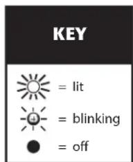
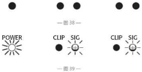
Illustration of hands inserting a wall socket into a socket, labeled as Figure 34 (no text or symbols on the diagram itself)LED Indicators
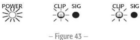
The green SIGNAL LED indicators light at approximately 0.1% of full power.
The red CLIP LED indicator fl ashes during overload (clipping). If the amplifi er's protection circuitry triggers protective muting, the signal and clip LEDs will not light. If this occurs during use, see the Troubleshooting section on page 17.
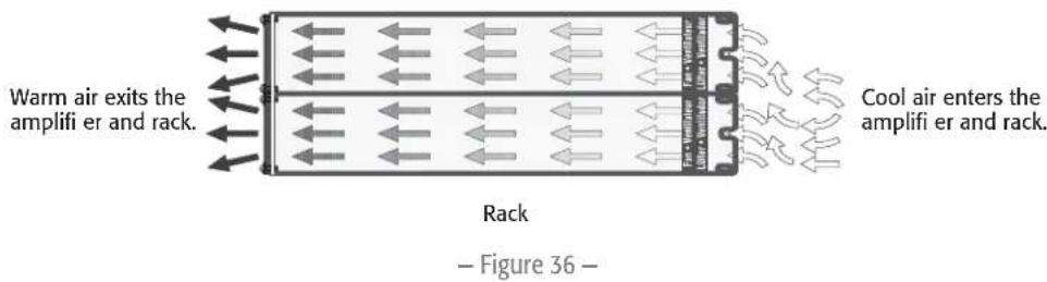
Fan Cooling
The fan speed varies automatically to maintain safe internal temperatures. Keep the front and rear vents clear to allow full air flow. Hot air exhausts out the front of the amp so it does not heat the interior of the rack. Make sure that plenty of cool air can enter the rack, especially if there are other units which exhaust hot air into it.
Safe Operating Levels
The amp's protective muting system guards against excessive internal temperatures. With normal ventilation and 4 - to 8Ω loads, the amplifier will handle any signal level including overdrive-but make sure that the speakers can handle the full power! However, lower load impedances and higher signal levels produce more internal heating. Into 2Ω loads, frequent or prolonged clipping (indicated by constant flashing of the red CLIP LED) may trigger protective muting. Bridged mono mode doubles the output impedance of the amp; 4Ω is the minimum load impedance. Heavy clipping may cause muting. If this happens, see the Troubleshooting section on page 17.
text_image
CHANNEL 1 ATTEN CHANNEL 2 ATTEN CLIP SIG 14 10 8 18 6 24 4 ∞ (34dB) 0 CLIP SIG 14 10 8 18 6 24 4 ∞ (34dB) 0- Figure 35 -
Model Maximum Voltage Gain
| CMX 300Va 31.6 x (30 dB) |
| CMX 500Va 40 x (32 dB) |
| CMX 800Va 46 x (33 dB) |
CMX 2000Va 31.6 x (30 dB)
- Table 4 -
text_image
Warm air exits the amplifier and rack. Rack Cool air enters the amplifier and rack. Figure 36 -Troubleshooting
Problem: No Sound
Indication: POWER indicator not lit
Check the AC plug. Also check the circuit breaker on the rear panel.
Confirm that the AC outlet works by plugging in another device. If too many amplifiers are used on one outlet, the building's circuit breaker may trip and shut off power.
text_image
KEY = lit = blinking = off– Figure 37 –
An overload in Bridged Mono mode may cause the amplifier to click off for several seconds. Check the load impedance (4Ω minimum), or reduce signal level.
An amplifi er which keeps shutting off may have a serious internal fault. Turn it off, remove AC power, and have the amplifi er serviced by a qualifi ed technician.
Indication: SIGNAL LED responding to signal level
If the green SIGNAL indicators are lighting normally, the fault is somewhere between the amp and the speaker. Check the speaker wiring for breaks. Try another speaker and cable.
Indication: SIGNAL LED not lit
If the green POWER indicator LED is lit and the fan is running, yet the signal LEDs indicate no signal, check the input. Make sure the signal source is operating and try another input cable. Connect the source to another channel or amplifier to confirm its operation.
Indication: CLIP LED fl ashing
If the red CLIP indicator fl ashes when signal is applied, the amplifier output may be shorted. Check the speaker wiring for stray strands or breaks in the insulation.
Indication: CLIP LEDs bright and steady
The amplifier is in protective muting.
One second of muting is normal when the amp is turned on or off.
Overheating will cause protective muting. The fan will be running at full speed and the chassis will be hot to the touch; sound should resume within a minute as the amplifi er cools to a safe operating temperature. Check for proper ventilation. If the fan isn't running at all, the amplifi er requires servicing.
Problem: Distorted Sound
Indication: CLIP LED flashing
POWER SIG SIGCLIP CLIP

POWER SIG SIGCLIP CLIP

text_image
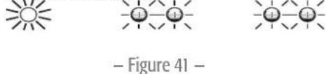
- Figure 39 -POWER SIG SIGCLIP CLIP

text_image
- Figure 40 -POWER SIG SIGCLIP CLIP
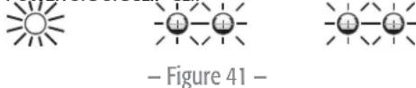
text_image
- Figure 41 -
– Figure 42 –
If the red CLIP indicator flashes before the signal indicator does, the load impedance is abnormally low or shorted. Unplug each speaker one-by-one at the amplifi er. If the CLIP LED goes out when you disconnect a cable, that cable or speaker is shorted. Try another cable and speaker to locate the fault.
Indication: CLIP LED not fl ashing
This could be caused by a faulty speaker or loose connection. Check the wiring and try another speaker.
The signal source may be clipping. Keep the amplifi er attenuation controls at mid point so that the source does not have to be overdriven.

– Figure 43 –

– Figure 44 –
Problem: No channel separation
Check the switch settings on the back of the amplifier. Make sure the "Parallel Input" and "Bridge Mode" switches are OFF in dual-channel, bi-amp, or stereo use where different signals go to each channel.
Make sure other equipment in the signal path, such as mixers, preamps, etc., are set for stereo, not mono.
Problem: Hum
Move cabling and signal sources to identify "hot spots" in the system. Cables with faulty shielding are a frequent entry point for hum.
Problem: Hiss
Unplug the amplifier input to confirm that the hiss is coming from the source or a device upstream; erratic or popping noises indicate an electronic fault in the offending unit.
To keep the normal noise floor low, operate the primary signal source at full level, without clipping, and avoid boosting the signal further between the source and the amplifier.
Problem: Squeals and feedback
Microphone feedback should be controlled with mixer controls. If noise continues to build up with zero mic gain, there is a serious fault in the signal processors or cables. Working in succession from the signal source towards the amplifier, check each device in the signal path by reducing its gain or unplugging it.
Specifications
| Stereo Mode (both channels driven) | ||||
| 8Ω/FTC 20 Hz - 20 kHz / 0.1% THD | 185 W | 260 W | 450 W | 1050 W |
| 8Ω/EIA 1 KHZ / 0.1% THD | 200 W | 300 W | 500 W | 1100 W |
| 4Ω/FTC 20 Hz - 20 KHZ / 0.1% THD | 280W | 400 W | 650 W | 1600 W |
| 4Ω/EIA 1 KHZ / 0.5% THD | 300 W | 500 W | 800 W | |
| 4Ω/EIA 1 KHZ / 1% THD | 2000 W | |||
| 2Ω/EIA 1 KHZ / 1% THD | 430 W | 700 W | 1200 W | 2500 W |
| 70 V - Direct drive / EIA 1 kHz / 1% THD | - | - | 400 W | 2500 W |
| 100 V - Direct drive / EIA 1 kHz / 1% THD | 1000 W | |||
| Bridge Mono Mode | ||||
| 8Ω/FTC 20 Hz - 20 kHz / 0.1%THD | 530 W | 800 W | 1300 W | 3200 W |
| 8Ω/EIA 1 kHz / 0.1%THD | 600 W | 900 W | 1500 W | 3600 W |
| 4Ω/EIA 1 kHz / 1%THD | 830 W | 1400 W | 2400 W | 5000 W |
| 70 V - Direct drive / EIA 1 kHz / 1% THD | 600 W | 1200 W | 2000 W | |
| 100 V - Direct drive / EIA 1 kHz / 1% THD | - | 600 W | 2300 W | 3600 W |
| 140 V - Direct drive / EIA 1 kHz / 1% THD | 5000 W | |||
| Distortion (SMPTE-IM) < 0.02% < 0.01% < 0.01% < 0.01% | ||||
| Signal to Noise (20 Hz - 20 kHz) 8Ω >-100 dB | ||||
| Input Sensitivity 8Ω | 1.15 V (+3.4 dBu) | 1.15 V (+3.4 dBu) | 1.23 V (+4.0 dBu) | 1.42 V (+5.3 dBu) |
| Voltage Gain (8Ω) 30 dB 32 dB 33 dB 36 dB | ||||
| Output Circuitry Class AB Class AB 2-tier Class H | 3-tier Class H | |||
| Power Requirements | ||||
| Typical, 1/8 power, pink noise at 4Ω | ||||
| 120 VAC | 4.4 A | 5.4 A | 6.3 A | 13.9 A |
| 230 VAC | 2.2 A | 2.7 A | 3.2 A | 7 A |
| Severe, 1/3 power pink noise at 4Ω | ||||
| 120 VAC | 6.6 A | 9.6 A | 15.6 A | 26.9 A |
| 230 VAC | 3.3 A | 4.8 A | 7.8 A | 13.5 A |
| Frequency Response | 20 Hz - 20 kHz, +0, -1 dB -3 dB points:5 Hz and 50 kHz (LF filter bypassed / 8Ω) | 20 Hz - 20 kHz, +/- 1 dB dB -3 dB points:5 Hz and 50 kHz (LF filter bypassed / 8Ω) | ||
| Damping Factor >300 at 8Ω | ||||
| Input Impedance (Ω) | 10 kΩ unbalanced / 20 kΩ balanced | |||
| Input Clipping | 10 Vrms (+22 dBu) | 6.4 Vrms (+18 dBu) | ||
| Cooling | Continuously variable speed fan, back-to-front air flow | |||
| Connectors (each channel) | Input: Active balanced; barrier strip, XLR and 1/4" (6.3 mm) TRS tip and XLR (pin 2 positive)Output: Detachable terminal block and NL4 | |||
| Controls | Front: AC Switch, Channel 1 and Channel 2 attenuation knobsRear: 10-position DIP switch | |||
| Indicators | Power-on: Green LED / Signal: Green LED (1 per channel) / Clip: Red LED (1 per channel) | |||
| Amplifier Protection | Stable into reactive or mismatched loads | |||
| Load Protection | On/off muting, AC Coupling | On/off muting, triac crowbar on each channel | ||
| Dimensions (HWD) | 2RU | 3RU | ||
| Inches | 3.5 x 19 x 15 | 5.25 x 19 x 15 | ||
| Millimeters | 89 x 483 x 381 | 133 x 483 x 381 | ||
| Weight | ||||
| Net | 35 lb (15.9 kg) | 40 lb (18.2 kg) | 44.5 lb (20.2 kg) | 75 lb (34 kg) |
| Shipping | 41 lb (18.6 kg) | 46 lb (20.9 kg) | 50.5 lb (23.0 kg) | 87 lb (39.5 kg) |
QSC™
Mailing Address:
QSC Audio Products, LLC
1675 MacArthur Boulevard
Costa Mesa, CA 92626-1468 USA
Telephone Numbers:
Main Number: (714) 754-6175
Sales & Marketing: (714) 957-7100 or toll free (USA only) (800) 854-4079
Customer Service: (714) 957-7150 or toll free (USA only) (800) 772-2834
Facsimile Numbers:
Sales & Marketing FAX: (714) 754-6174
Customer Service FAX: (714) 754-6173
World Wide Web:
www.qsc.com
E-mail:
info@qsc.com
service@qsc.com
Serie CMXa
Manual del usuario
CMX 300Va
CMX 500Va
CMX 800Va
CMX 2000Va
text_image
QSC CMX 300Va PROFESSIONAL AMPLIFIER ON POWER CHANNEL 1 ACTION CHANNEL 2 ACTION CLIP SIB CLIP SIB CHANNEL 1 ACTION CHANNEL 2 ACTION QSC CMX 500Va PROFESSIONAL AMPLIFIER ON POWER CHANNEL 1 ACTION CHANNEL 2 ACTION CLIP SIB CLIP SIB CHANNEL 1 ACTION CHANNEL 2 ACTION QSC CMX 800Va PROFESSIONAL AMPLIFIER ON POWER CHANNEL 1 ACTION CHANNEL 2 ACTION CLIP SIB CLIP SIB CHANNEL 1 ACTION CHANNEL 2 ACTION QSC CMX 2000Va PROFESSIONAL AMPLIFIER ON POWER CHANNEL 1 ACTION CHANNEL 2 ACTION CLIP SIB CLIP SIB CHANNEL 1 ACTION CHANNEL 2 ACTIONtext_image
1 = + 2 = + 3 = -XLR no balanceado Patilla 1 a patilla 3 del puente — Figura 26 —
natural_image
Diagram of a mechanical tool with a magnified inset showing a component (no text or symbols present)text_image
Diagram illustrating a probe tip with labeled parts and electric field lines, likely illustrating a physics or engineering concept.Balanceado
natural_image
Illustration of a pen with a curved arrow indicating motion or force (no text or symbols)No balanceado
- Figura 28 -
Salidas
NL4 Salidas
natural_image
Two technical line drawings of electrical socket or socket components, one circular and one axial view, with no text or symbols present.120 VAC 220-240 VAC
- Figura 33 -

natural_image
Line drawing of a hand pressing a wall socket with an arrow indicating the direction (no text or symbols)- Figura 34 -
text_image
CHANNEL 1 ATTEN CHANNEL 2 ATTEN CLIP SIG 14 10 8 18 6 24 4 ∞ (34dB)0 CLIP SIG 14 10 8 18 6 24 4 ∞ (34dB)0- Figura 35 -
text_image
Diagram illustrating airflow or heat transfer through a multi-layered structure with labeled components and directional arrowsQSC Audio Products, LLC
1675 MacArthur Boulevard
flowchart
graph LR
    A["Ch. 1 input"] --> B["Ch. 1"]
    C["Ch. 2 input"] --> D["Ch. 2"]
    B --> E["Waveform with high-frequency oscillations"]
    D --> F["Waveform with low-frequency oscillations"]
- Figure 17 -
Channel 2 Can Be Used to Daisy-chain to Other Amplifiers. — Figure 22 —
Installation
text_image
1 = south 2 = + - 3 = -natural_image
Diagram of a mechanical tool with a magnified inset showing a component (no text or symbols)text_image
Diagram illustrating a soldering or dislocation process with labeled components and directional arrowséquilibrés
natural_image
Illustration of a mechanical component with a shaft and base, showing no text or symbolsTerminal Block Connector Wiring UL IEC
| Wire range - 6 mm | 2 | |
| Solid wire (AWG) 28 - 10 - | ||
| Stranded wire (AWG/mm2 ) 28 - 10 - | ||
| Torque (lb.-in.) 6 - | ||
| Wire strip length | 7 - 8 mm | - |
- Table 3 -
text_image
CH1 OUTPUT → CH2 OUTPUT BRIDGE MONO 2- Figure 32 -
Tension opératoire
Model Maximum Voltage Gain
| CMX 300Va 31.6 x (30 dB) |
| CMX 500Va 40 x (32 dB) |
| CMX 800Va 46 x (33 dB) |
| — Table 4 — |
natural_image
Two technical line drawings of electrical socket or socket components, one circular and one axial view (no text or symbols)120 VAC 220-240 VAC
- Figure 33 -
natural_image
Hand inserting a wall socket into a socket, with an arrow indicating the direction (no text or symbols present)- Figure 34 -
text_image
CHANNEL 1 ATTEN CHANNEL 2 ATTEN CLIP SIG 12 10 8 14 6 18 4 24" (34dB) 0 ∞ (34dB) 0 CLIP SIG 12 10 8 14 6 18 4 24" (34dB) 0- Figure 35 -
text_image
- Figure 38 -POWER SIG SIGCLIP CLIP

text_image
- Figure 39 -POWER SIG SIGCLIP CLIP

text_image
- Figure 40 -POWER SIG SIGCLIP CLIP
text_image
- Figure 41 -
- Figure 42 -
text_image
POWER CLIP SIG CLIP SIG — Figure 43 —
- Figure 44 -
QSC Audio Products, LLC
1675 MacArthur Boulevard
text_image
1 2 3 4 5 6 7 8 9 10 11 CH1 INPUT CH1 INPUT PENUTS PENUT PENUT PENUT PENUT PENUT PENUT PENUT PENUT PENUT PENUT PENUT PENUT PENUT PENUT PENUT PENUT PENUT PENUT PENUT PENUT PENUT PENUT PENUT PENUT PENUT PENOUT PENOUT PENOUT PENOUT PENOUT PENOUT PENOUT PENOUT PENOUT PENOUT PENOUT PENOUT PENOUT PENOUT PENOUT PENOUT PENOUT PENOUT PENOUT PENOUT PENOUT PENOUT PENOUT PENOUT PENOUT PENUT PENUT PENUT PENUT PENUT PENUT PENUT PENUT PENUT PENUT PENUT PENUT PENUT PENUT PENUT PENUT PENUT PENUT PENUT PENUT PENUT PENUT PENUT PENUT PEN UT U P N T U N T U N T U N T U N T U N T U N T U N T U N T U N T U N T U N T U N T U N T U N T U N T U N T U N T U N T U N T U N T U N T U N T U N T U N T U N T U N T U N T U N T U N T U N T U N T U N T U N T U NT U NT U NT U NT U NT U NT U NT U NT U NT U NT U NT U NT U NT U NT U NT U NT U NT U NT U NT U NT U NT U NT U NT U NT U NT U NT U NT U NT U NT U NT U NT U NT U NT U NT U NT U NT U NT U NT U NT U NT U NT U NT U NT U NT U NT U NT U NT U NT U NT U NT UNTUPT MUSNOSO 1. SET THE UP PENTES 1A TO AND TO 1B TO THE 1C SET THE UP PENTES 1A TO AND TO 1B TO THE 1C SET THE UP PENTES 1A TO AND TO 1B TO THE 1C SET THE UP PENTES 1A TO AND TO 1B TO THE 1C SET THE UP PENTES 1A TO AND TO 1B TO THE 1C SET THE UP PENTES 1A TO AND TO 1B TO THE 1D SET THE UP PENTES 1A TO AND TO 1B TO THE 1C SET THE UP PENTES 1A TO AND TO 1B TO THE 1D SET THE UP PENTES 1A TO AND TO 1B TO THE 1C SET THE UP PENTES 1A TO AND TO 1B TO THE 1D SET THE UP PENTES 1A TO AND TO 1B TO THE 1E SET THE UP PENTES 1A TO AND TO 1B TO THE 1F SET THE UP PENTES 1A TO AND TO 1B TO THE 1G SET THE UP PENTES 1A TO AND TO 1B TO THE 1H SET THE UP PENTES 1A TO AND TO 1B TO THE 1I SET THE UP PENTES 1A TO AND TO 1B TO THE 1J SET THE UP PENTES 1A TO AND TO 1B TO THE 1K SET THE UP PENTES 1A TO AND TO 1B TO THE 1L SET THE UP PENTES 1A TO AND TO 1B TO THE 1M SET THE UP PENTES 1A TO AND TO 1B TO THE 1N SET THE UP PENTES 1A TO AND TO 1B TO THE 20T SETTHE UP PENTES 1A TO AND TO 1B TO THE 20T SETTHE UP PENTES 1A TO AND TO 1B TO THE 20T SETTHE UP PENTES 1A TO AND TO 1B TO THE 20T SETTHE UP PENTES 1A TO AND TO 1B TO THE 20T SETTHE UP PENTES 1A TO AND TO 1B TO THE20T SETTHE UP PENTES 1A TO AND TO 1B TO THE 20T SETTHE UP PENTES 1A TO AND TO 1B TO THE20T SETTHE UP PENTES 1A TO AND TO 1B TO THE20T SETTHE UP PENTES 1A TO AND TO 1B TO THE20T SETTHE UP PENTES 1A TO AND TO 1B TO THE20T SETTHE UP PENTES 1A TO AND TO 1B TO THE20T SETTHE UP PENTES 1A TO AND TO 1B TO THUPT MUSNOSO 2. SET THE UP PENTES AS MARGED BY THE UNLESS MUSNOSO (UNLESS MUSNOSO) (UNLESS MUSNOSO) (UNLESS MUSNOSO) (UNLESS MUSNOSO) (UNLESS MUSNOSO) (UNLESS MUSNOSO) (UNLESS MUSNOSO) (UNLESS MUSNOSO) (UNLESS MUSNOSO) (UNLESS MUSNOSO) (UNLESS MUSNOSO) (UNLESS MUSNOSO)- Abbildung 3 -
text_image
1 = b 2 = + 3 = -XLR unbalanced Jumper pin 1 to pin 3 — Abbildung 26 —
natural_image
Diagram of a mechanical device with a magnified inset showing a tool interacting with a component (no text or symbols present)TRS unbalanced No modification needed — Abbildung 27 —
text_image
Diagram illustrating a mechanical or electrical setup with labeled components and directional arrows, possibly indicating motion or force.- Abbildung 28 -
Ausgänge
NL4 Ausgänge
text_image
KEY = lit = blinking = off— Abbildung 37 —
POWER SIG SIGCLIP CLIP

- Abbildung 38 -
POWER SIG SIGCLIP CLIP

- Abbildung 39 -
POWER SIG SIGCLIP CLIP

- Abbildung 40 -
POWER SIG SIGCLIP CLIP

- Abbildung 41 -
POWER SIG SIGCLIP CLIP

- Abbildung 42 -
POWER SIG SIGCLIP CLIP

- Abbildung 43 -


- Abbildung 44 -
QSC Audio Products, LLC
1675 MacArthur Boulevard
Costa Mesa, CA 92626-1468 USA
Telefonnummern:
service@qscaudio.com
CMXa 系列
用户手册
CMX 300Va
CMX 500Va
CMX 800Va
CMX 2000Va
text_image
QSC CMX 300Va PROFESSIONAL AMPLIFIER ON POWER CHANNEL 1 ATTEN CHANNEL 2 ATTEN CLIP SIO CLIP SIO CLIP SIO CLIP SIO CLIP SIO CLIP SIO CLIP SIO CLIP SIO CLIP SIO CLIP SIO CLIP SIO CLIP SIO CLIP SIO CLIP SIO CLIP SIO CLIP SIO CLIP SIO CLIP SIO CLIP SIO CLIP SIO CLIP Sio CLIP Sio CLIP Sio CLIP Sio CLIP Sio CLIP Sio CLIP Sio CLIP Sio CLIP Sio CLIP Sio CLIP Sio CLIP Sio CLIP Sio CLIP Sio CLIP Sio CLIP Sio CLIP Sio CLIP Sio CLIP Sio CLIP Sio CLIP SIO CLIP Sio CLIP Sio CLIP Sio CLIP Sio CLIP Sio CLIP Sio CLIP Sio CLIP Sio CLIP Sio CLIP Sio CLIP Sio CLIP Sio CLIP Sio CLIP Sio CLIP Sio CLIP Sio CLIP Sio CLIP Sio CLIP SIO CLIP SIO CLIP SIO CLIP SIO CLIP SIO CLIP SIO CLIP SIO CLIP SIO CLIP SIO CLIP SIO CLIP SIO CLIP SIO CLIP SIO CLIP SIO CLIP SIO CLIP SIO CLIP SIO CLIP SIO CLIP SIO CLIP SSO CLIP SSO CLIP SSO CLIP SSO CLIP SSO CLIP SSO CLIP SSO CLIP SSO CLIP SSO CLIP SSO CLIP SSO CLIP SSO CLIP SSO CLIP SSO CLIP SSO CLIP SSO CLIP SSO CLIP SSO CLIP SSO CLIP SSO CLIP SSSO CLIP SSSO CLIP SSSO CLIP SSSO CLIP SSSO CLIP SSSO CLIP SSSO CLIP SSSO CLIP SSSO CLIP TSSO CLIP TSSO CLIP TSSO CLIP TSSO CLIP TSSO CLIP TSSO CLIP TSSO CLIP TSSO CLIP TSSO符号说明
text_image
1 = -h 2 = + 3 = -natural_image
Diagram of a mechanical device with a magnifying glass and tool, no visible text or symbolsTRS非平衡无需任何修改
—图27—
text_image
Diagram illustrating a mechanical or electrical component with labeled parts and motion arrows, possibly indicating movement or force.均衡

natural_image
Illustration of a pen tip with a handle and base, showing no text or symbols不平衡
一图28一
输出
NL4 输出
natural_image
Two technical line drawings of electrical socket or socket components, no text or symbols present120 VAC 220-240 VAC
—图33—
衰减控件
natural_image
Line drawing of a hand inserting a wall socket into a socket (no text or symbols)— 图 34 —
LED 指示灯
text_image
KEY = 指标灯亮着 = 指标灯闪烁 = 该指示灯不亮一图37一
POWER SIG SIGCLIP CLIP
text_image
—图 38— POWER CLIP SIG —图 39— CLIP SIGPOWER SIG SIGCLIP CLIP

text_image
图 40—POWER SIG SIGCLIP CLIP

text_image
—图 41—


一图44
问题:嘶嘶声
QSC Audio Products, LLC
1675 MacArthur Boulevard
Costa Mesa, CA 92626-1468 USA
电话:
总机:(714) 754-6175