
SPA4100 - Receiver QSC - Free user manual and instructions
Find the device manual for free SPA4100 QSC in PDF.
| Product Type | Professional audio power amplifier (receiver) |
| Brand | QSC |
| Model | SPA4100 |
| Number of Channels | 4 channels |
| Output Power (Stereo 8 Ω) | 100 W per channel |
| Output Power (Stereo 4 Ω) | 100 W per channel |
| Bridge Mode Power (8 Ω or 4 Ω) | 200 W per pair |
| Bridge Mode Power 70 V / 100 V | 350 W per pair |
| Frequency Response | 20 Hz - 20 kHz ±0.1 dB |
| Signal-to-Noise Ratio | >100 dB (20 Hz - 20 kHz) |
| Output Circuit | Class D |
| Built-in Protections | Limiter, thermal protection, short circuit, automatic MUTE |
| Operating Modes | Stereo, Bridge 4 Ω/8 Ω, Bridge 70 V/100 V (with 80 Hz high-pass filter) |
| Input Connectors | Euroblock 3.5 mm 10-pin (green) |
| Output Connectors | 2 × Euroblock 5 mm 4-pin (green) |
| Remote Control Connectors | Euroblock 3.5 mm 10-pin (black) for volume and standby |
| Power Supply | 100-240 V~, 50-60 Hz, with active power factor correction |
| Dimensions (H × W × D) | 43 mm × 220 mm × 241 mm (1U) |
| Net Weight | 1.8 kg |
| Gross Weight | 3.0 kg |
| Cooling | Natural convection |
| Operating Temperature | 0 °C to 40 °C |
| Certifications | UL, CE, Energy Star, FCC Class B, RoHS/WEEE, UL 2043 with plenum kit |
| Box Contents | Amplifier, power cord, connectors, 19" rack ears, quick start guide, safety documentation |
| Warranty | Refer to document TD-000453 provided |
Frequently Asked Questions - SPA4100 QSC
User questions about SPA4100 QSC
0 question about this device. Answer the ones you know or ask your own.
Ask a new question about this device
Download the instructions for your Receiver in PDF format for free! Find your manual SPA4100 - QSC and take your electronic device back in hand. On this page are published all the documents necessary for the use of your device. SPA4100 by QSC.
USER MANUAL SPA4100 QSC
System Power Amplifier (SPA)
Installation Guide
SPA2-60 Amplifier SPA4-60 Amplifier
SPA2-200 Amplifier SPA4-100 Amplifier
EXPLANATION OF SYMBOLS
The term "WARNING!" indicates instructions regarding personal safety. If the instructions are not followed the result may be bodily injury or death.
The term "CAUTION!" indicates instructions regarding possible damage to physical equipment. If these instructions are not followed, it may result in damage to the equipment that may not be covered under the warranty.
The term "IMPORTANT!" indicates instructions or information that are vital to the successful completion of the procedure.
The term "NOTE" is used to indicate additional useful information.

The intent of the lightning flash with arrowhead symbol in a triangle is to alert the user to the presence of un-insulated "dangerous" voltage within the product's enclosure that may be of sufficient magnitude to constitute a risk of electric shock to humans.

The intent of the exclamation point within an equilateral triangle is to alert the user to the presence of important safety, and operating and maintenance instructions in this manual.
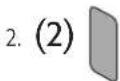
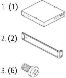
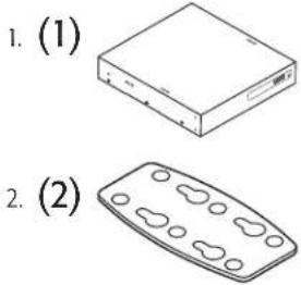
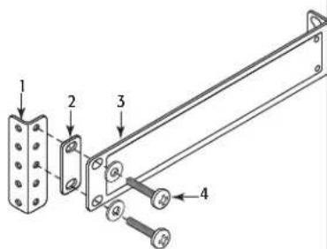
What's in the Box
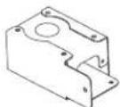
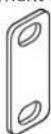
| (1x) | (1x) | (2x) | (2x) | |
| SPA2-60SPA2-200SPA4-60SPA4-100 |  | AC Power Cord,US | Rack EarQSC P/NCH-001344-00 | Joining PlateQSC P/NCH-001345-00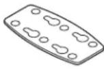 |
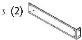
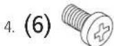
| (2x) | (6x) | (6x) | (4x) | |
| Rack-Ear SpacerQSC P/NCH-001386-00 |  [2DXA] [2DXA] | Phillips Pan HeadM4 x 7 mm[3DX2] | Phillips FlatheadM3 x 6 mm[208T] | Foam SpacerQSC P/NPL-001023-00[1H876] |
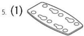
| (1x) | SPA 2-channel (1x)SPA 4-channel (2x) | SPA 2-channel (1x) | SPA 2-channel (1x) | |
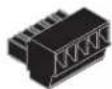
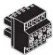
| Rack-Ear Cover LabelQSC P/NLB-001138-00 | 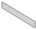 | Euro Plug 3.5 mm,4 pos, grnQSC P/NCO-000646-00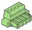 | Euro Plug 3.5 mm,5 pos, grnQSC P/NCO-000644-00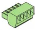 | Euro Plug 3.5 mm,4 pos, blkQSC P/NCO-000645-00 |
| SPA 4-channel (1x) | SPA 4-channel (1x) | (1x) | (1x) | |
| Plug 3.5 mm,10 pos, grnQSC P/NCO-000647-00 |  [233G] [233G] | Plug 3.5 mm,10 pos, grnQSC P/NCO-000648-00 | WarrantyTD-000453 | Safety InformationTD-000337 |
Installation
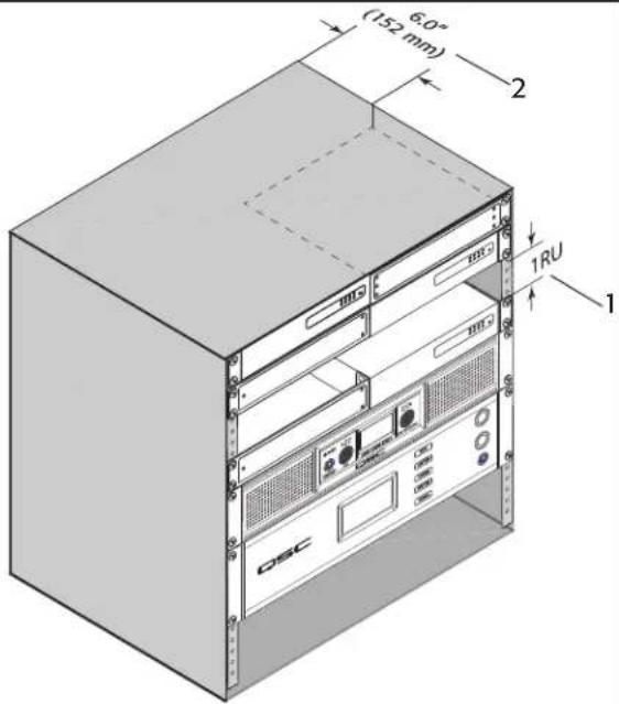
Ventilation
- Recommend 1RU (1.75 in / 44.45 mm) space above the amplifier.
• Minimum open space of 6 inches measured from back of amplifier.

NOTE: QSC System Power Amplifiers contain advanced protection circuitry which allows them to reduce output power in order to maintain safe operating temperatures. Insufficient ventilation may result in the amplifier reducing output power during normal operation (indicated by Limiter/Protect LEDs illuminating red). To reduce the possibility of thermal limiting, and allow proper heat dissipation, we recommend that you keep the space directly above and to the rear of these amplifiers free of obstacles.
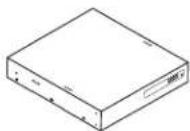
- Figure 1 -
Select the Amplifier Installation Configuration
Choose one of the following configuration options:
A. One Amplifier 19-inch Rack (Left or Right Mount) on page 3 D. Under Table or on Wall on page 4
B. Two Amplifiers 19-inch Rack (Front or Rear Facing Out) on page 3 E. Free-Standing on Desk/Table on page 5
C. One Amplifier Half Rack (Front or Rear Facing Out) on page 4 F. Plenum Installation on page 5
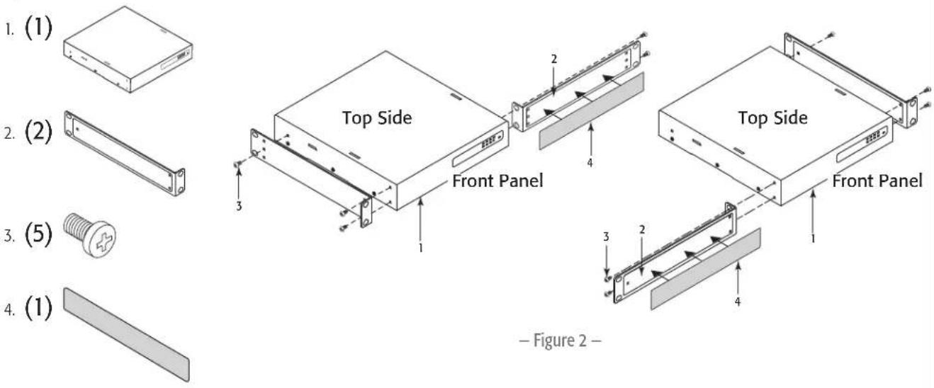
A. One Amplifier 19-inch Rack (Left or Right Mount)
Figure 2
B. Two Amplifiers 19-inch Rack (Front or Rear Facing Out)
Figure 3
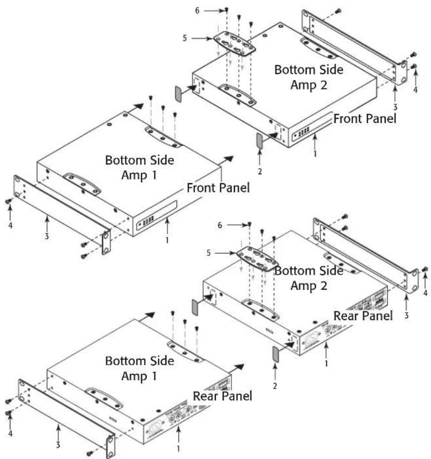
- Figure 3 -
C. One Amplifier Half Rack (Front or Rear Facing Out)
Figure 4
- Figure 4 -
D. Under Table or on Wall
Figure 5.
- (6)
- (4) Not supplied – use appropriate screws for mounting surface.
- Mounting Surface
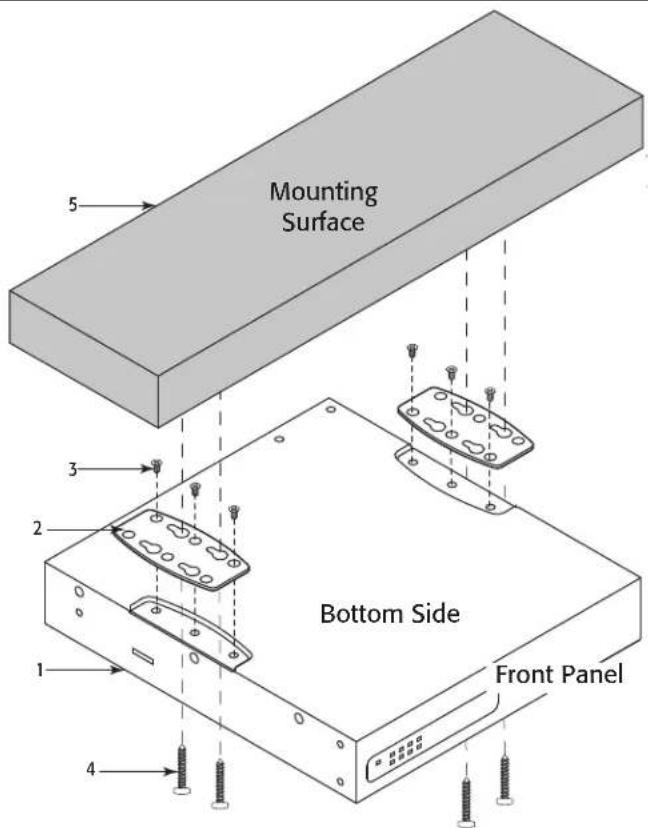
- Figure 5 -
E. Free-Standing on Desk/Table
Figure 6
1. (1)
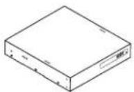
- (4)

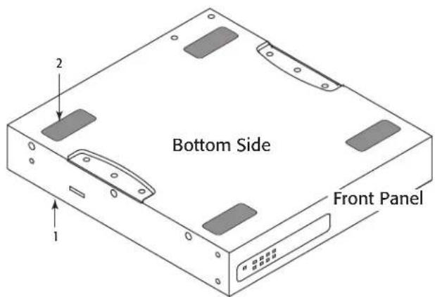
- Figure 6 -
F. Plenum Installation
Configure amplifier per option D Under Table or on Wall.
Figure 7
1. (1)
- (1)
Plenum Kit - Suitable for Air Handling Spaces only when used with optional Plenum Kit (FG-000995-00) sold separately.
- Figure 7 -
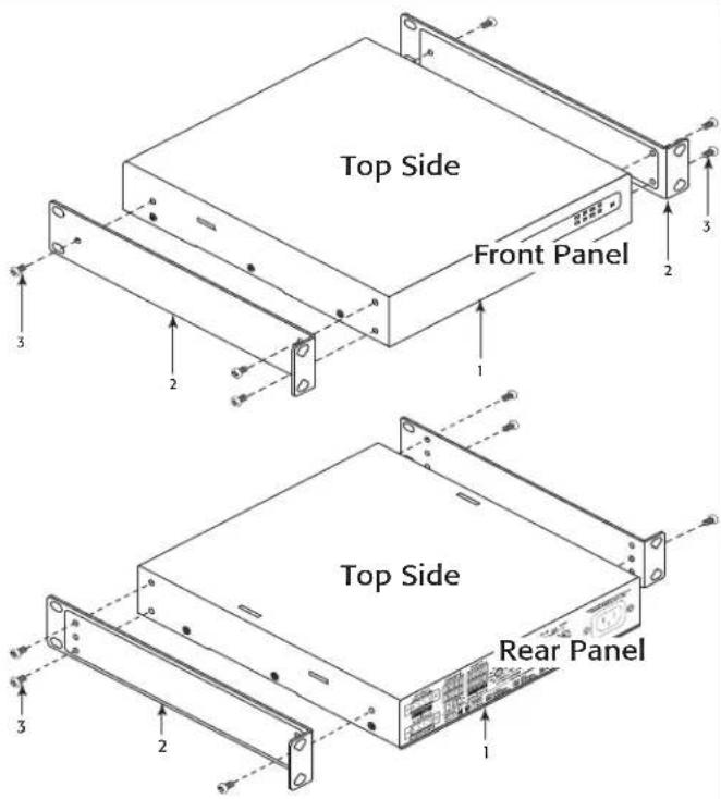
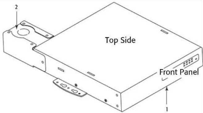
Rack-Mounting Options
All Configurations
Figure 8
Using the examples shown, you can mount any of the amplifier configurations. The example at the lower right of Figure 8 can be flipped to accommodate a single amplifier on the left side.
-
Equipment Rack (not supplied)
-
(2)
Optional – to bring flush with Q-Sys Core 110
-
(2)

-
(4) Rack-Mounting Screws and Washers (not supplied)
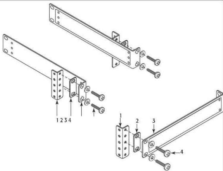
- Figure 8 -
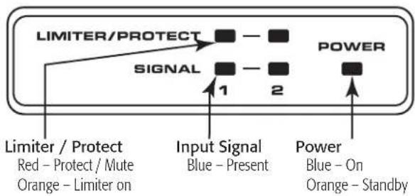
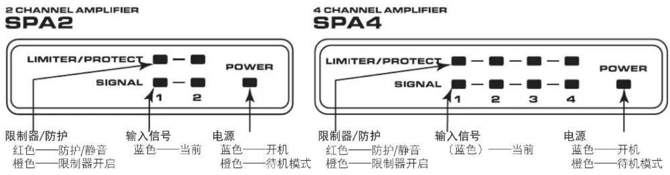
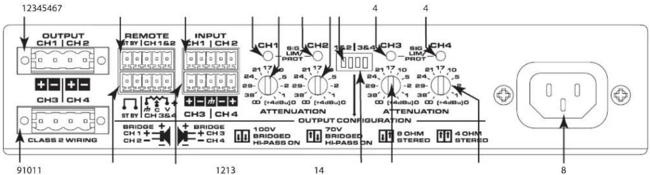
Front Panel
2 CHANNEL AMPLIFIER
SPA2
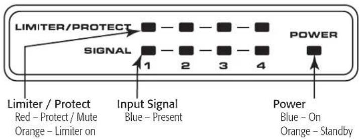
4 CHANNEL AMPLIFIER
SPA4
- Figure 9 -
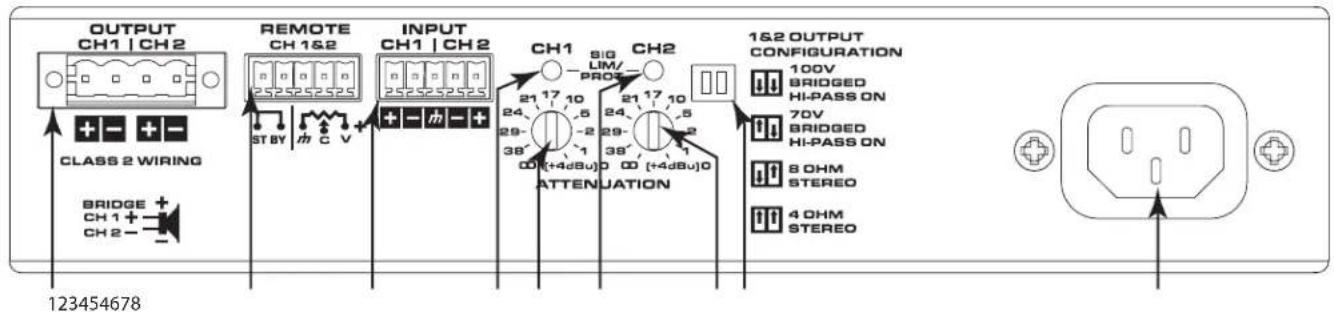
Rear Panel
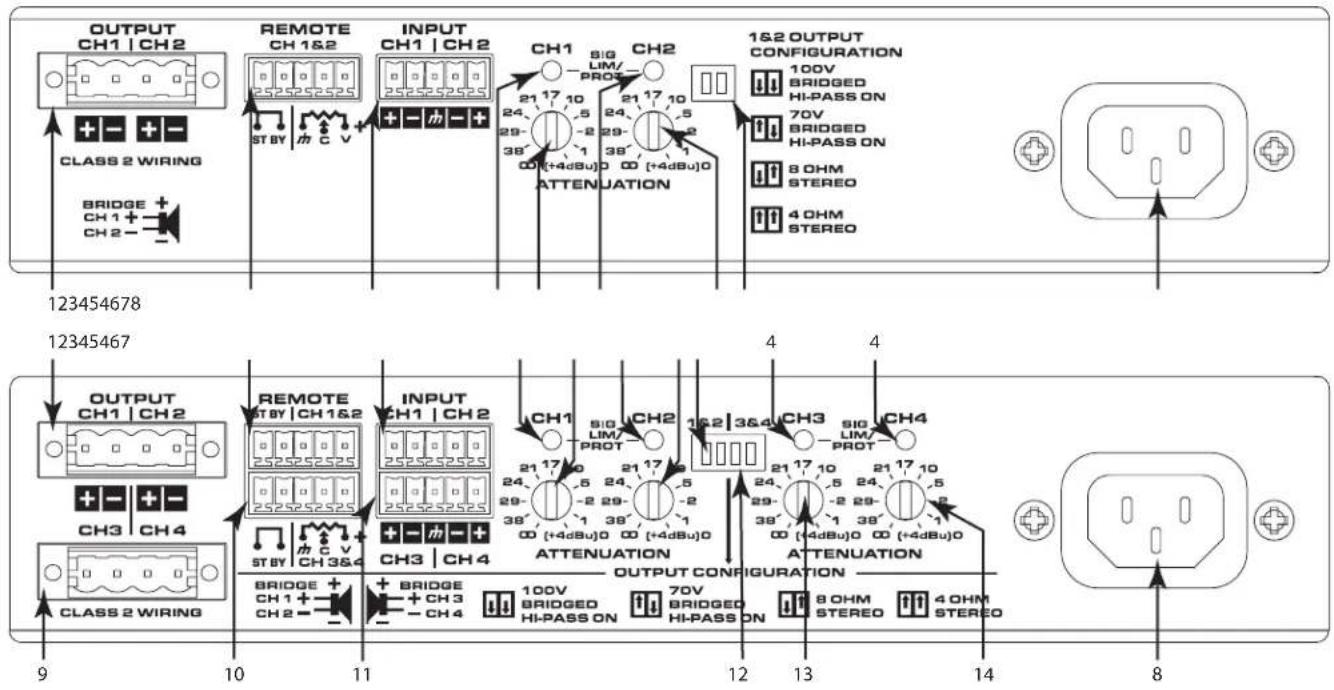
-
Figure 10 -
-
Output Channels 1 & 2
- Remote Control Channels 1 & 2
- Input Channels 1 & 2
-
Channel 1 thru Channel 4 Status LEDs
a. Green - Normal Signal Level
b. Amber - Input or Output Overload/Clipping or Thermal Limiting
c. Red - Limit or Protect Mode
d. Red - Thermal Limit or Protect Mode
e. Red - Mute -
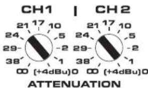
Channel 1 Attenuator Control
- Channel 2 Attenuator Control
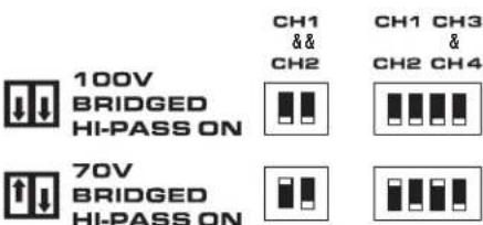
- Mode Configuration Switches Channel 1&2
- AC Power Connection
-
Output Channels 3 & 4
-
Remote Control Channel 3 & 4
- Input Channels 3 & 4
- Mode Configuration Switches Channel 3 & 4
- Channel 3 Attenuator Control
- Channel 4 Attenuator Control
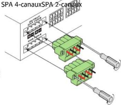
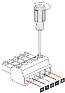
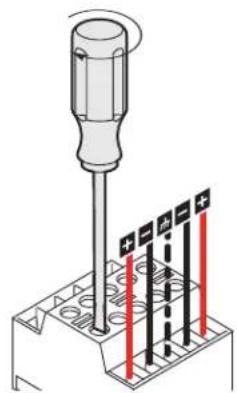
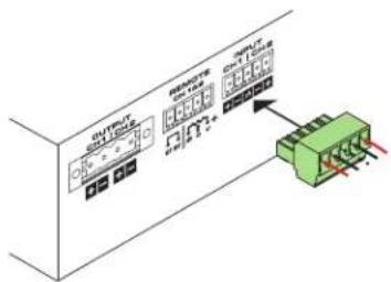
Connections
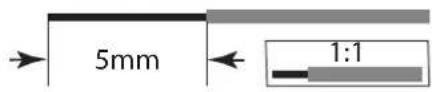
Wire

IMPORTANT: Class 2 Wiring
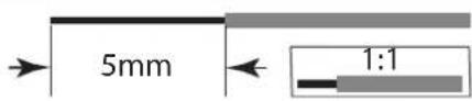
Strip Length = 5mm
DO NOT TIN!
- Figure 11 -
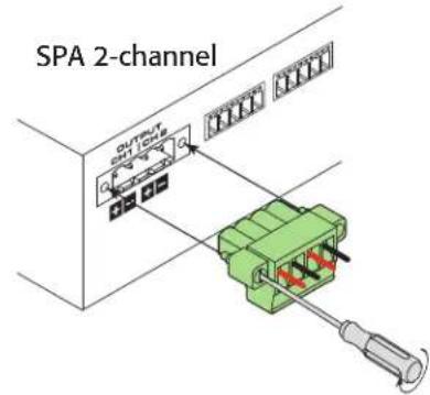
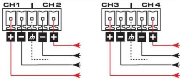
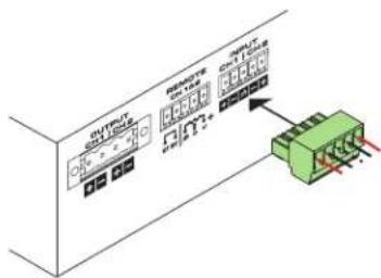
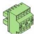
Output Connectors

IMPORTANT: Class 2 Wiring
Figure 12 - Figure 13
SPA 2-channel
(1)
SPA 4-channel
(2)
- Figure 12 -
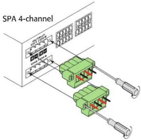
- Figure 13 -
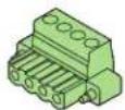
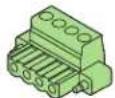
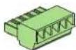
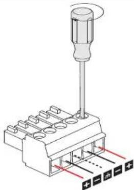
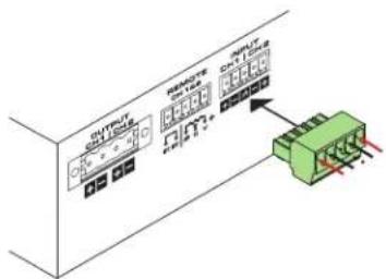
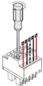
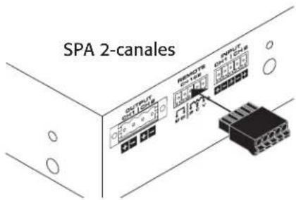
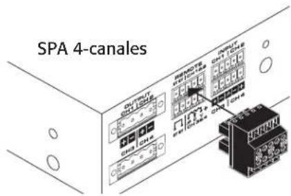
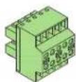
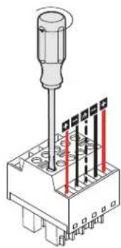
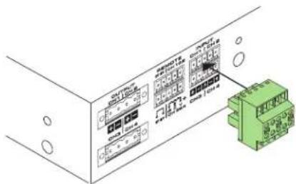
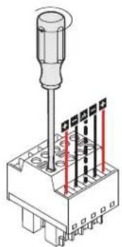
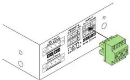
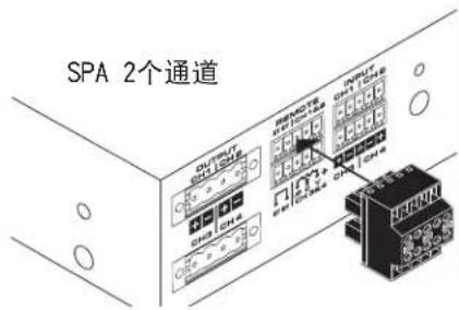
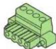
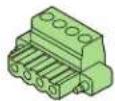
Input Connectors
SPA 2-channel Connector
Figure 14 - Figure 15
(1)
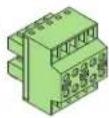
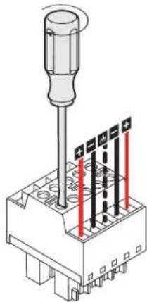
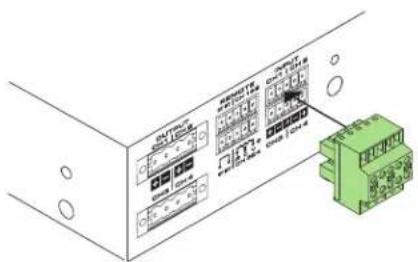
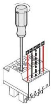
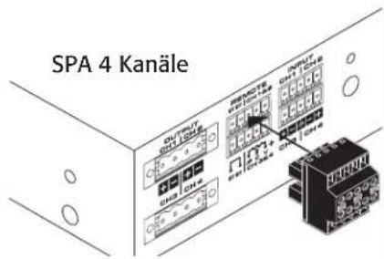
SPA 4-channel Connector
Figure 16 - Figure 17
(1)
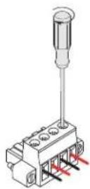
natural_image
Technical diagram of a screwdriver connector with pin layout and wiring (no text or symbols)- Figure 14 -
natural_image
Diagram of a screwdriver inserted into an electrical connector with three red indicator lights (no text or symbols)- Figure 16 -
- Figure 15 -
- Figure 17 -
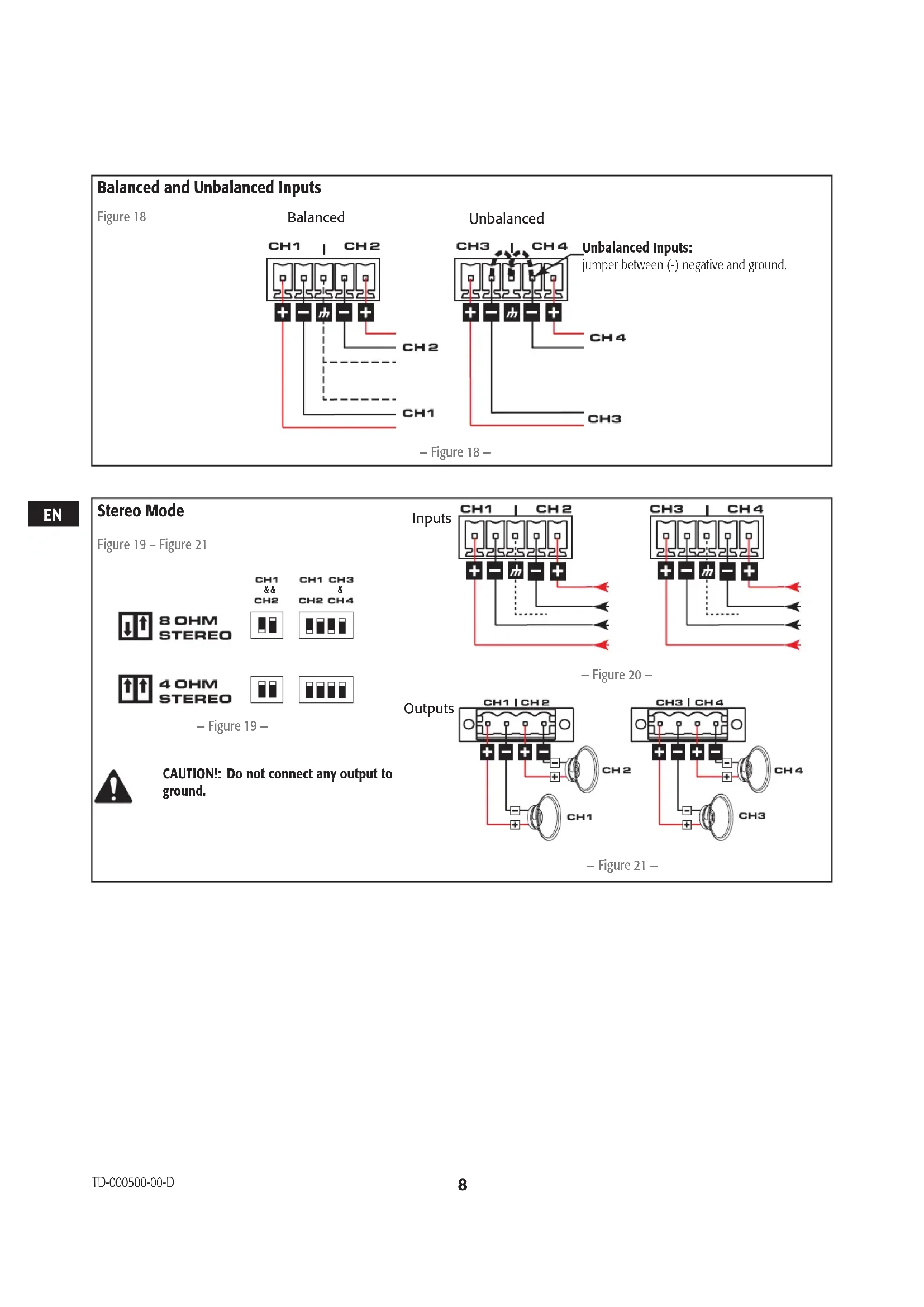
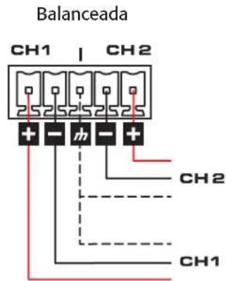
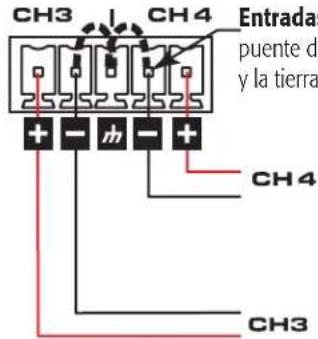
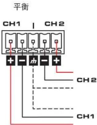
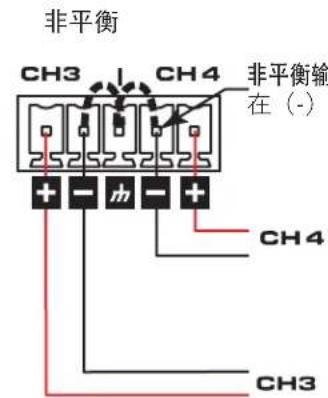
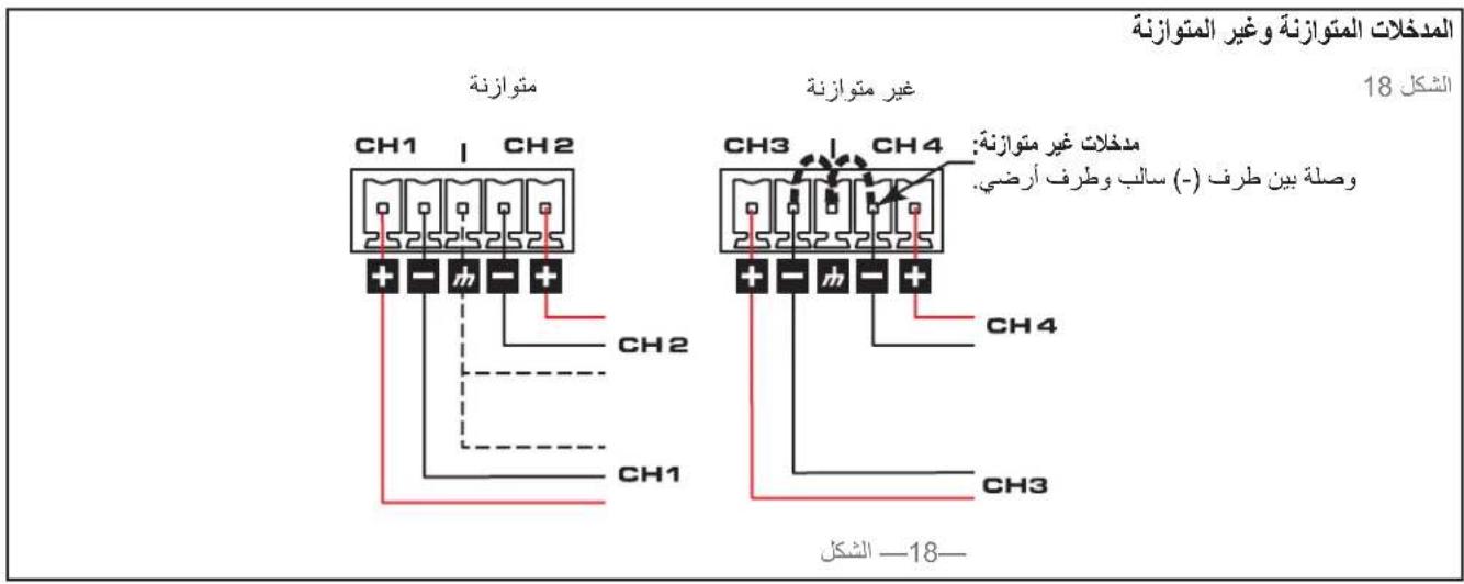
Balanced and Unbalanced Inputs
Figure 18
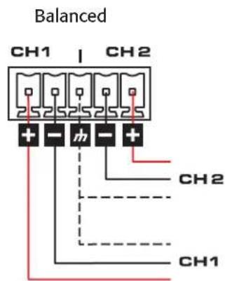
- Figure 18 -
Unbalanced Inputs: jumper between (-) negative and ground.
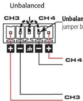
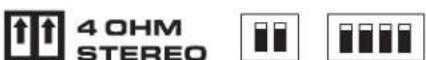
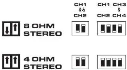
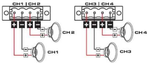
Stereo Mode
Figure 19 – Figure 21
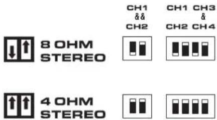
- Figure 19 -
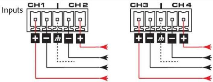
- Figure 20 -

- Figure 21 -

CAUTION!: Do not connect any output to ground.
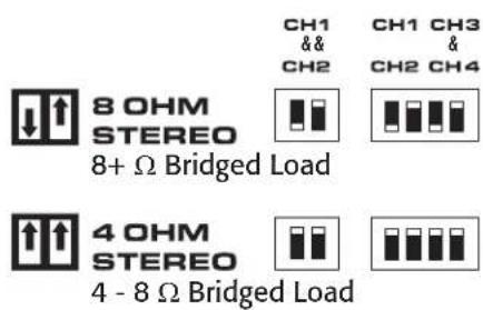
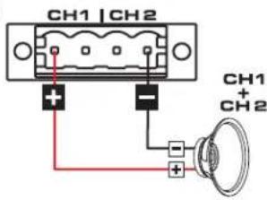
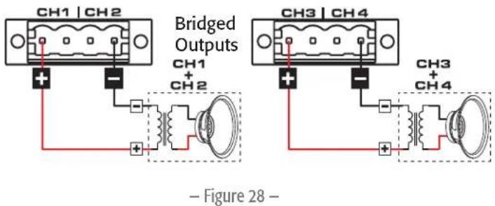
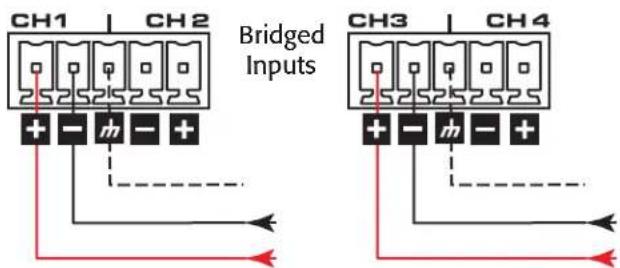
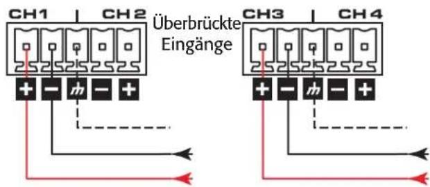
4 or 8-ohm Bridged Mode
Figure 22 - Figure 25
- Figure 22 -
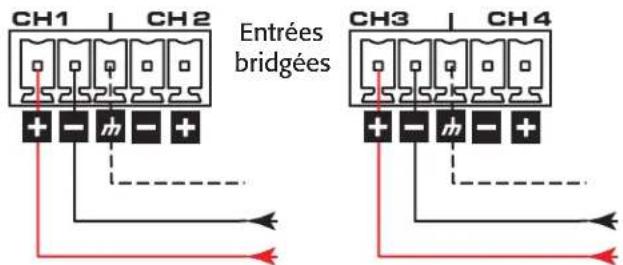
Inputs
- Figure 23 -
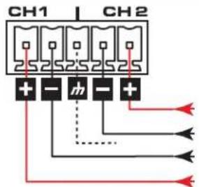
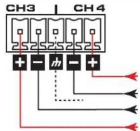
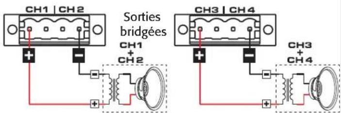
Outputs
- Figure 24 -

CAUTION!: Do not connect any output to ground.

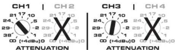
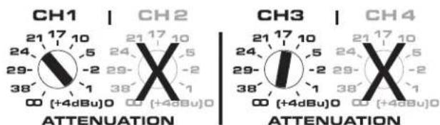
IMPORTANT: When using 4 or 8-ohm Bridged Mode, use both signal inputs of a channel pair (for example parallel CH1&2 inputs and parallel CH3&4 inputs), and set the attenuation for each channel pair to the same level.

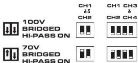
NOTE: 80 Hz (high-pass filter) is auto-engaged in bridged 70 V and 100 V modes
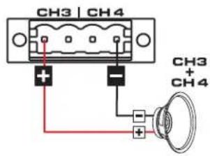
Figure 26 - Figure 29
- Figure 26 -
Minimum Load Impedance:
- 70V Bridged = 16 Ω
- 100V Bridged = 26 Ω
- Figure 27 -
- Figure 29 -
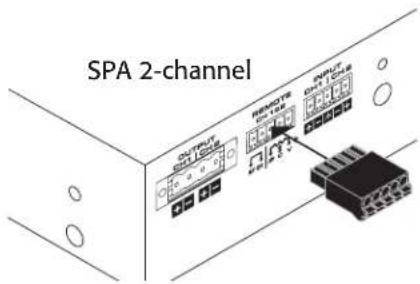
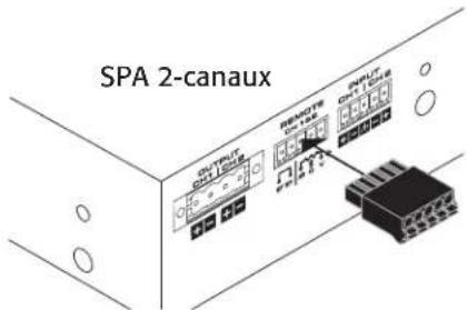
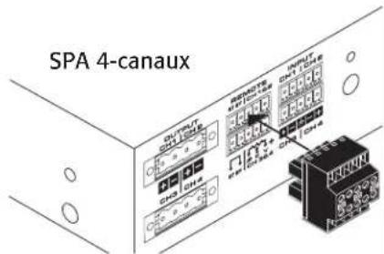
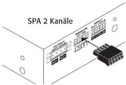
Remote
Figure 30 - Figure 32
SPA 2-channel
(1)
3.5mm, 5-pin
SPA 4-channel
(1)
3.5mm, 10-pin
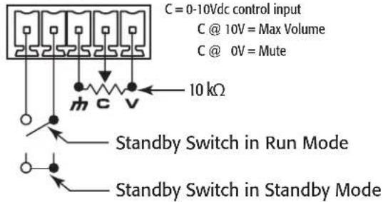
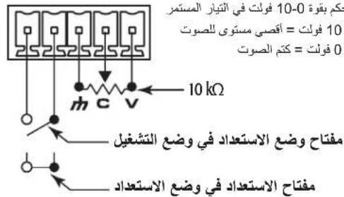
When the potentiometer is at the minimum position, the amplifier goes into Mute mode. On the SPA 4-channel amplifier, the remote level controls for channel 1 & 2 are independent from channels 3 & 4 remote level control.
On the SPA 4-channel model, closing the "Standby Switch" between the first two pins of either Ch1-Ch2 or Ch3-Ch4 causes all four channels to go into Standby.
CH 1&2
- Figure 30 -
V = +10Vdc reference output
C = 0-10Vdc control input C @ 10V = Max Volume C @ 0V = Mute
natural_image
Technical diagram of a screwdriver inserted into an electrical connector housing (no text or symbols visible)- Figure 31 -

- Figure 32 -
Specifications
| SPA2-602 Channels | SPA4-604 Channels | SPA2-2002 Channels | SPA4-1004 Channels | |
| Stereo Mode (all channels driven) | ||||
| 8 Ω 60 W 60 W 200 W 100 W | ||||
| 4 Ω 60 W 60 W 200 W 100 W | ||||
| Bridged Outputs (per bridged output pair) | ||||
| 8 Ω and 4 Ω 200 W 200 W 400 W 200 W | ||||
| 70 V 250 W 250 W | ; | 350 W 350 W | ; | |
| 100 V 250 W 250 W | ; | 350 W 350 W | ; | |
| Frequency Response (4 Ω and 8 Ω) 20 Hz - 20 kHz +/- 0.1 dB | ||||
| Signal to Noise (20 Hz - 20 kHz) >100 dB | ||||
| Input Sensitivity 1.23 V (+4 dBu) | ||||
| Gain at 8 Ω 25 dB 25 dB 30 dB 27 dB | ||||
| Output Circuitry Class D | ||||
| Input Impedance >10k, balanced or unbalanced | ||||
| Maximum Input Level 12.3 V (+24 dBu) | ||||
| Cooling | Convection | |||
| Input Connectors | ||||
| SPA 2-channel | 3.5 mm Euro, 5 pin (green) | |||
| SPA 4-channel | 3.5 mm Euro, 10 pin (green) | |||
| Remote Connectors | ||||
| SPA 2-channel | 3.5 mm Euro, 5 pin (black) | |||
| SPA 4-channel | 3.5 mm Euro, 10 pin (black) | |||
| Output Connectors | ||||
| SPA 2-channel | One 5 mm Euro, 4 pin (green) | |||
| SPA 4-channel | Two 5 mm Euro, 4 pin (green) | |||
| Front Panel Indicators Power, Signal (per channel), Limit/Mute/Protect (per channel) | ||||
| Rear Panel Indicators | Two-colored LED Signal/Limit/Mute/Protect (per channel) | |||
| User-configurable Operating Modes(4-channel or equivalent operating mode can be independently configured per channel pair | Low Impedance 4 Ω and 8 Ω operation, orHigh-impedance bridged direct drive of 70V & 100V distributed audio systems | |||
| General Purpose Inputs (GPI) | Remote Volume, Remote Standby, on 3.5 mm connectors (10k potentiometer is not included) | |||
| Highpass Filter | 80 Hz auto-engaged in Bridged 70 V & 100 V modes | |||
| Dimensions 1.7" x 8.7" x 9.5" (43 mm x 220 mm x 241 mm) | ||||
| Net Weight | 3.5 lb (1.6 kg) | 4.0 lb (1.8 kg) | 3.5 lb (1.6 kg) | 4.0 lb (1.8 kg) |
| Shipping Weight | 6 lb (2.7 kg) | 6.5 lb (3.0 kg) | 6 lb (2.7 kg) | 6.5 lb (3.0 kg) |
| Power Requirements | Universal Power Supply (with active power factor correction), 100 - 240 VAC, 50 - 60 Hz | |||
| Agency Approvals | UL, CE, Energy Star, RoHS/WEEE compliant, FCC Class B (Conducted and Radiated emissions), UL 2043 with PL-KIT | |||
| Carton Contents | IEC Cable, Installation Guide, Connector Pack, Rack Mount Ears, Mounting Brackets | |||
1 Peak Power – dependent on channel loading
QSC™
Mailing Address:
QSC, LLC
1675 MacArthur Boulevard
Costa Mesa, CA 92626-1468 USA
Telephone Numbers:
Main Number: (714) 754-6175
Sales & Marketing: (714) 957-7100 or toll free (USA only) (800) 854-4079
Customer Service: (714) 957-7150 or toll free (USA only) (800) 772-2834
Facsimile Numbers:
Sales & Marketing FAX: (714) 754-6174
Customer Service FAX: (714) 754-6173
World Wide Web:
www.qsc.com
E-mail:
info@qsc.com
service@qsc.com
System Power Amplifier (SPA)
Guía de instalación
- Figura 1 -
natural_image
Technical diagram of a screwdriver inserted into an electrical connector housing (no text or symbols visible)- Figura 14 -
natural_image
Technical diagram of a screwdriver inserted into an electrical connector housing (no text or symbols visible)- Figura 16 -

- Figura 15 -

natural_image
Technical line drawing of an electronic device rear panel with a green connector block attached (no visible text or symbols)- Figura 17 -
Entradas balanceadas y no balanceadas
Figura 18
No balanceada
4 - 8 Ω Bridged Load

chemical
Chemical resonance peaks for CH1 and CH2 molecular orbitals with attenuation values labeled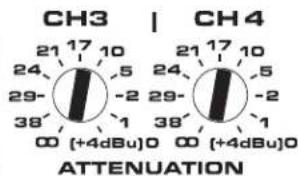
- Figura 25 -
natural_image
Technical diagram of a screwdriver inserted into an electrical connector housing (no text or symbols visible)- Figura 31 -
- Figura 32 -
Especificaciones
- Figure 1 -
- Figure 13 -
Figure 16 – Figure 17
(1)
natural_image
Technical line drawing of a screwdriver connector with pin layout (no text or symbols)- Figure 14 -
natural_image
Technical diagram of a screwdriver inserted into an electrical terminal block with red indicator lights (no text or symbols)- Figure 16 -

- Figure 15 -
natural_image
Technical line drawing of an electronic device rear panel with a green connector base (no visible text or symbols)- Figure 17 -
Figure 19 - Figure 21
- Figure 19 -
Entrées
- Figure 20 -
Sorties
- Figure 21 -
Figure 22 - Figure 25
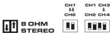
Figure 26 - Figure 29
- Figure 26 -
- Figure 27 -
- Figure 28 -
- Figure 29 -
Impédance minimum:
- 70V Bridge = 16 Ω
- 100V Bridge = 26 Ω
Télécommande
Figure 30 - Figure 32
SPA 2-canaux
(1)
3,5 mm, 5 broches
SPA 4-canaux
(1)
3,5 mm, 10 broches
natural_image
Technical diagram of a mechanical component with red and black vertical lines indicating internal structure (no text or symbols)- Figure 31 -
- Figure 32 -
- Abbildung 1 -
DE
natural_image
Technical diagram of a screwdriver inserted into an electrical connector housing (no text or symbols visible)- Abbildung 14 -
natural_image
Technical diagram of a screwdriver inserted into a terminal block with red indicator lights (no text or symbols)- Abbildung 16 -

- Abbildung 15 -
natural_image
Technical line drawing of an electronic device rear panel with labeled ports and a green connector block (no text or symbols present)- Abbildung 17 -
- Abbildung 26 -
natural_image
Technical diagram of a screwdriver inserted into an electrical terminal block with three vertical slots (no text or symbols)- Abbildung 31 -
- Abbildung 32 -
Technische Daten
一图1一
请选择放大器安装配置
请选择以下其中一个配置方案:
一 图 8 一
前面板
一图9一
后面板
一图10一
natural_image
Technical diagram of a screwdriver inserted into a connector housing (no text or symbols visible)一图14一
natural_image
Diagram of a screwdriver inserted into a base with red and black vertical bars indicating mounting points (no text or symbols present)一 图 16 —
一图15一

一 图 17 —
平衡输入和非平衡输入
图 18
chemical
Chemical resonance diagram showing CH1 and CH2 molecular orbitals with atomic charge distributions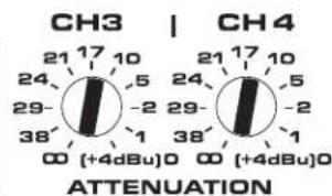
一图25一
70V / 100V 桥接模式
natural_image
Diagram of a screwdriver inserted into a base with three vertical pins, no text or symbols present一图31一

一图32一
规格
natural_image
Technical diagram of a mechanical assembly with a screwdriver and connector housing (no text or symbols)—Рис.14—
—Рис.15—

natural_image
Diagram of a screwdriver inserted into a housing with three vertical pins (no text or symbols present)—Рис.16—

natural_image
Technical line drawing of an electronic device rear panel with internal components and a green connector block (no text or symbols visible)—Рис.17—
—1—
التهوية
الصوت.
LED LED LED LED LED LED LED LED LED LED LED LED LED LED LED LED LED LED LED LED LED LED LED LED LED LED LED LED LED LED LED LED LED LED LED LED LED LED LED LED LED LED LED LED LED LED LED LED LED LED LED LED LED LED LED LED LED LED LED LED LED LED LED LED LED LED LED LED LED LED LED LED LED LED LED LED LED LED LED LED LED LED LED LED LED LED LED LED LED LED LED LED LED LED LED LED LED LED LED LED LED
ال clkقية مطفة.
— 11—
natural_image
Diagram of a screwdriver inserted into a terminal block with red and black vertical bars indicating pins (no text or symbols present)الشكل —16—

الشكل —17—

natural_image
Technical diagram of a mechanical assembly with a screwdriver and connector housing (no text or symbols)الشكل —14—

الشكل —15—
موصلات الإخراج
: هام

$$ 3 1 - 2 1 \text { الشكل } $$
2 قنوات SPA
(1)
4 قتوات SPA
(2)
موصلات الإدخال
قُنوات 2 موصل SPA
$$ 5 1 - 4 1 \text { الشكل } $$

قُنوات 4 موصل SPA
$$ 7 1 - 6 1 \text { الشكل } $$
natural_image
Diagram of a screwdriver inserted into a terminal block with three red vertical bars (no text or symbols)الشكل—31—
CH 1&2
QSC Audio Products, LLC
1675 MacArthur Boulevard
Costa Mesa, CA 926261468 USA
أرقام الهETF:
(714) 754-6175 : الرقمический