
CX404 - Receiver QSC - Free user manual and instructions
Find the device manual for free CX404 QSC in PDF.
| Product Type | 4-channel Power Amplifier |
| Brand | QSC |
| Model | CX404 |
| Output Power (20 Hz - 20 kHz, 0.05% THD) | 4 ohms/channel: 170 W; 8 ohms/channel: 250 W |
| Output Power (1 kHz, 1% THD) | 4 ohms/channel: 450 W; bridged 8 ohms: 900 W |
| Frequency Response | 20 Hz - 20 kHz, ±0.2 dB; -3 dB at 8 Hz and 100 kHz |
| Signal-to-Noise Ratio | -106 dB (unweighted, 20 Hz - 20 kHz) |
| Voltage Gain | 36.5x (31 dB) |
| Input Sensitivity | 1.22 Vrms (+3.9 dBu) for 8 ohms; 1.16 Vrms (+3.5 dBu) for 4 ohms |
| Input Impedance | 12 kΩ balanced, 6 kΩ unbalanced |
| Damping Factor | >500 at 8 ohms |
| Output Circuit Type | Class AB |
| Protection | Short-circuit, open-circuit, thermal, ultrasonic, RF; stable into reactive loads |
| Cooling | Variable speed fan, rear-to-front airflow |
| Input Connectors | 3-pin terminal block (per channel) |
| Output Connectors | Barrier strip with protective cover |
| DataPort Connectors | 2 QSC DataPort connectors (full V1 feature set) |
| Power Supply | 100, 120, or 220-240 V~, 50-60 Hz (factory configured) |
| Current Consumption | Idle 0.7 A; 1/8 power (8 Ω) 8.1 A; 1/3 power 12.2 A; full power 22 A (at 120 V) |
| Dimensions (W x H x D) | 48.3 cm x 8.9 cm x 35.6 cm |
| Weight | 9.5 kg net; 12.3 kg gross |
| Maintenance and Cleaning | Disconnect before cleaning. Use a dry cloth. Do not use aerosols, liquids, or disinfectants. |
| Serviceability | Refer all repairs to a QSC authorized service center. Limited warranty, see QSC website. |
| Supplied Accessories | User manual, safety cover, adhesive feet, input and output connectors, IEC power cord |
Frequently Asked Questions - CX404 QSC
User questions about CX404 QSC
0 question about this device. Answer the ones you know or ask your own.
Ask a new question about this device
Download the instructions for your Receiver in PDF format for free! Find your manual CX404 - QSC and take your electronic device back in hand. On this page are published all the documents necessary for the use of your device. CX404 by QSC.
USER MANUAL CX404 QSC
2-Channel Low-impedance Models:
CX302
CX502
CX702
CX902
CX1102
4-Channel Low-impedance Models:
CX254
CX404
70 Volt Direct Output Models:
CX204V
(4-channel)
CX302V
(2-channel)
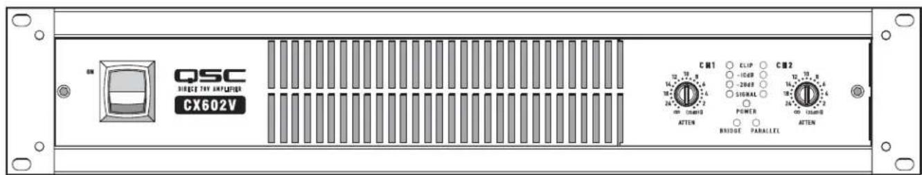
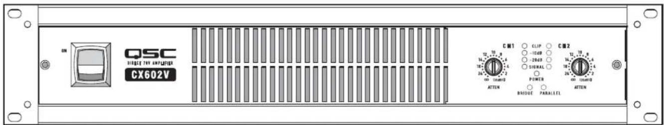
CX602V (2-channel, 8 ohm)
CX1202V (2-channel, 4 and 8 ohm)
EXPLANATION OF SYMBOLS
The term "WARNING!" indicates instructions regarding personal safety. If the instructions are not followed the result may be bodily injury or death.
The term "CAUTION!" indicates instructions regarding possible damage to physical equipment. If these instructions are not followed, it may result in damage to the equipment that may not be covered under the warranty.
The term "IMPORTANT!" indicates instructions or information that are vital to the successful completion of the procedure.
The term "NOTE" is used to indicate additional useful information.


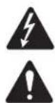
The intent of the lightning flash with arrowhead symbol in a triangle is to alert the user to the presence of un-insulated "dangerous" voltage within the product's enclosure that may be of sufficient magnitude to constitute a risk of electric shock to humans.
The intent of the exclamation point within an equilateral triangle is to alert the user to the presence of important safety, and operating and maintenance instructions in this manual.

IMPORTANT SAFETY INSTRUCTIONS


WARNING: TO PREVENT FIRE OR ELECTRIC SHOCK, DO NOT EXPOSE THIS EQUIPMENT TO RAIN OR MOISTURE.
- Read these instructions.
- Keep these instructions.
- Heed all warnings.
- Follow all instructions.
- Do not use this apparatus near water.
- Do not submerge the apparatus in water or liquids.
- Do not use any aerosol spray, cleaner, disinfectant or fumigant on, near or into the apparatus.
- Clean only with a dry cloth.
- Do not block any ventilation opening. Install in accordance with the manufacturer's instructions.
- Keep ventilation opening free of dust or other matter.
- Do not install near any heat sources such as radiators, heat registers, stoves, or other apparatus (including amplifiers) that produce heat.
- To reduce the risk of electrical shock, the power cord shall be connected to a mains socket outlet with a protective earthing connection.
- Do not defeat the safety purpose of the polarized or grounding-type plug. A polarized plug has two blades with one wider than the other. A grounding type plug has two blades and a third grounding prong. The wide blade or the third prong are provided for your safety. If the provided plug does not fit into your outlet, consult an electrician for replacement of the obsolete outlet.
- Protect the power cord from being walked on or pinched particularly at plugs, convenience receptacles, and the point where they exit from the apparatus.
- Do not unplug the unit by pulling on the cord, use the plug.
- Only use attachments/accessories specified by the manufacturer.
- Unplug this apparatus during lightning storms or when unused for long periods of time.
- Refer all servicing to qualified service personnel. Servicing is required when the apparatus has been damaged in any way, such as power-supply cord or plug is damaged, liquid has been spilled or objects have fallen into the apparatus, the apparatus has been exposed to rain or moisture, does not operate normally, or has been dropped.
- The appliance coupler, or the AC Mains plug, is the AC mains disconnect device and shall remain readily operable after installation.
- Adhere to all applicable, local codes.
- Consult a licensed, professional engineer when any doubt or questions arise regarding a physical equipment installation.
FCC Statement

NOTE: This equipment has been tested and found to comply with the limits for a Class B digital device, pursuant to Part 15 of the FCC Rules.
These limits are designed to provide reasonable protection against harmful interference in a residential installation. This equipment generates, uses and can radiate radio frequency energy and, if not installed and used in accordance with the instructions, may cause harmful interference to radio communications. However, there is no guarantee that interference will not occur in a particular installation. If this equipment does cause harmful interference to radio or television reception, which can be determined by turning the equipment off and on, the user is encouraged to try to correct the interference by one or more of the following measures:
Reorient or relocate the receiving antenna.
- Increase the separation between the equipment and receiver.
- Connect the equipment into an outlet on a circuit different from that to which the receiver is connected.
- Consult the dealer or an experienced radio/TV technician for help.
Maintenance and Repair

WARNING!: Advanced technology, e.g., the use of modern materials and powerful electronics, requires specially adapted maintenance and repair methods. To avoid a danger of subsequent damage to the apparatus, injuries to persons and/or the creation of additional safety hazards, all maintenance or repair work on the apparatus should be performed only by a QSC authorized service station or an authorized QSC International Distributor. QSC is not responsible for any injury, harm or related damages arising from any failure of the customer, owner or user of the apparatus to facilitate those repairs.
Warranty
For a copy of the QSC Limited Warranty, visit the QSC Audio Products website at www.qsc.com
Introduction
Thank you for purchasing this QSC power amplifier. Please read the following directions to obtain the best results.
The CX model line-up features:
- 2 channel and 4 channel low-impedance or transformerless 70V output models
Each channel pair has its own DataPort and Mode Switch
QSC DataPorts connect to the most advanced QSC accessories and monitoring systems
Mode switches for Clip Limit, Low Frequency Filter, Stereo, Bridge Mono, and Parallel Inputs
QSC PowerLight high-performance, compact, and light weight switching power supply - Complete amplifier protection and monitoring
- Barrier strip output connectors
- XLR and terminal block balanced input connectors
- Gain controls are recessed and detented
- Security cover for gain controls prevents tampering
Active inrush current limiting eliminates need for power sequencing
LED indicators for power, parallel or bridge mode, input signal presence, -20dB, -10dB, and clip/protect - Optional front panel handles
- Optional IT-42 isolated output transformer for CX302 for 25V, 70V, and 100V (or 50V, 140V, and 200V bridge mode)
Unpacking
Factory packed carton contains:
CX amplifier
- User's manual
Security cover for gain controls
- Adhesive rubber feet (for non-rack mount applications)
- 3-pin terminal block input connectors
- Spade lug output connectors
IEC-type detachable power cord
Use the same type carton when shipping the amplifier.
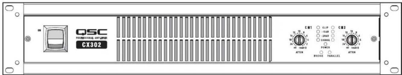
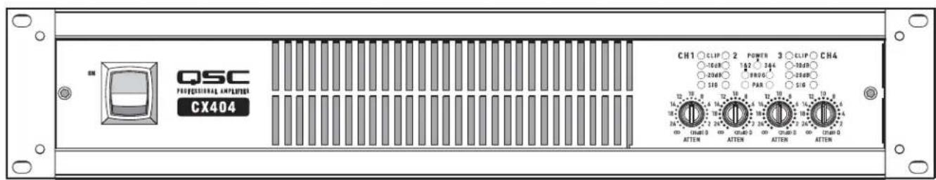
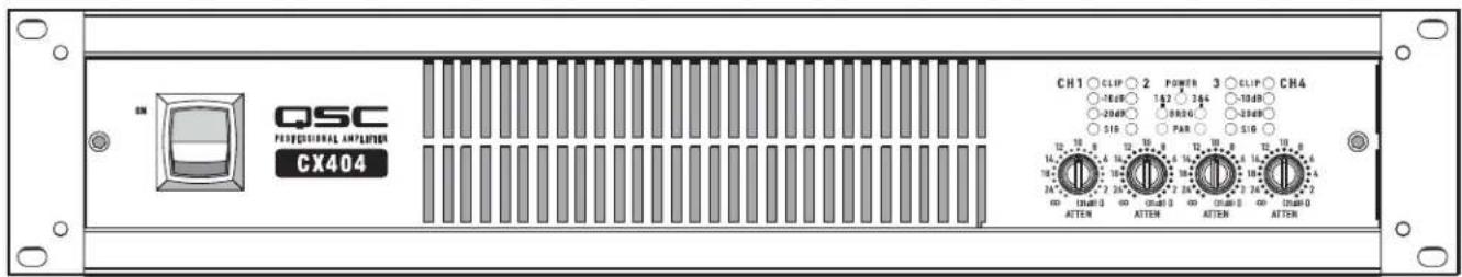
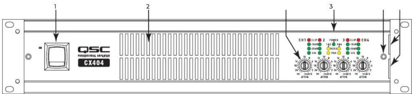
Front Panel
(CX404 shown in Figure 1, other models similar)
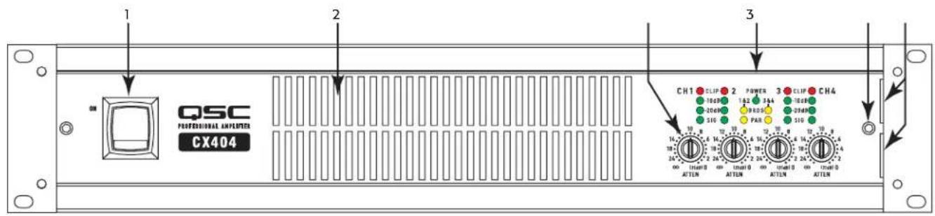
Figure 1
- Power Switch
- LED Indicators
- Cooling Air Exhaust Vents
- Security Panel Retaining Screw
- Gain Controls
- Security Panel Retaining Slots

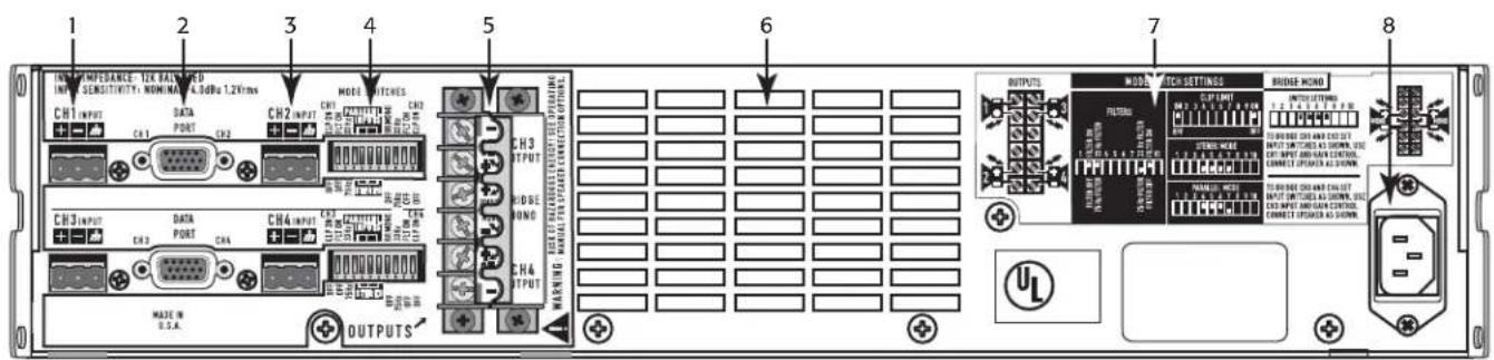
Rear Panel
(CX404 shown Figure 2, other models similar, 2-Ch. models equipped with XLR inputs as well)
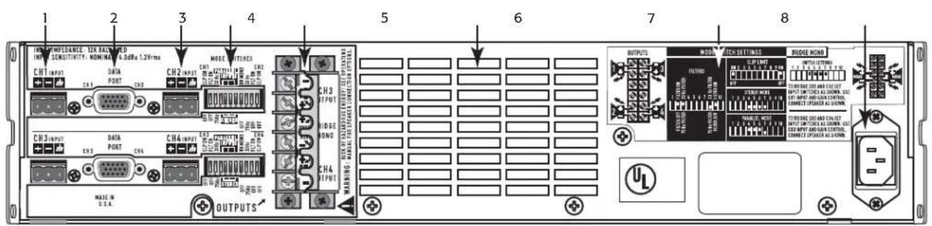
Figure 2
-
CH1 Terminal Block Input Connectors
-
Barrier Strip Output Connectors
-
DataPort Connector
-
Cooling Air Inlet Vents
-
CH2 Terminal Block Input Connectors
-
Mode Switch Setting Diagrams
-
Mode Switches
-
IEC Power Connector
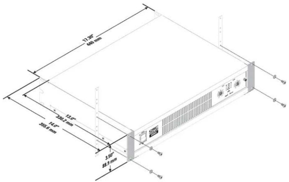
Rack Mounting
Optiona h s t the self-adhesive rubber feet to the bottom. (Figure 3)
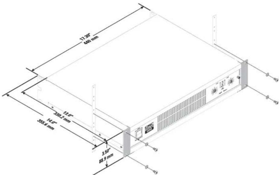
Figure 3
Cooling
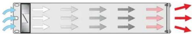
Cool Air flows from the back of the rack, into the back of the amplifier, and out the front. This keeps the rack cool. The fan automatically runs faster when the amp is working hard. (Figure 3)

CAUTION! Do not block the front or rear air vents!
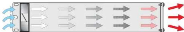
Figure 4
AC Mains Connection
-
Turn off the AC power switch before connecting AC power.
-
Connect AC power to the IEC socket on the back of the amplifier.

NOTE: The AC Switch must be turned on to use remote control systems or the Standby function.

CAUTION: The correct AC line voltage is shown on the serial number label, on the rear panel. Connecting to the wrong line voltage may damage the amplifier or increase the risk of electric shock.
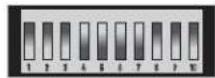
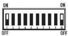
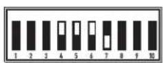
Setting the Mode Switches
Figure 5 is a typical Mode Switch block as seen from the rear of the amplifier (CX404V model shown).
Two-Channel Models: One mode switch controls each channel's independent clip limiting and low frequency (LF) filtering. The switches can set the amplifier's operating mode for Stereo, Parallel, or Bridge operation.
Four-Channel Models: There are two mode switches; one controls the operation of channels 1-2, the other controls the operation of channels 3-4. It is not possible to bridge or parallel channels 1 or 2 with channels 3 or 4.
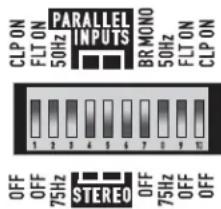
Figure 5

Figure 6
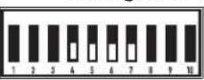
Setting Clip Limiters
Each channel has a clip limiter with its own on-off switch. The limiter only responds to actual clipping, and automatically compensates for load and voltage variations. Clip limiting is generally recommended, especially to protect high frequency drivers. (Figure 6)
- Set switch UP (ON position) to use Clip Limiting.
- Switch 1 controls the first channel.
- Switch 10 controls the second channel.
Selecting Stereo, Parallel, or Bridge Mode
Each of the channel pairs can be set for normal Stereo operation, Parallel Input mode, or Bridge Mono mode. On four-channel models, Ch.1 can be
bridged or paralleled with Ch.2; Ch.3 can be bridged or paralleled with Ch.4.
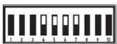
Stereo Mode: Each channel within the pair remains independent, and each may be used for a different signal. Switches 4, 5, 6 and 7 are all set to the DOWN position. (Figure 7)
Parallel Mode: This setting connects both inputs of a pair together. One signal feeds both channels. Do not connect different sources to each input. Each channel's Gain control and speaker connection remain independent. Switches 4, 5, and 6 are set to the UP position. Switch 7 is set to the DOWN position. (Figure 8)
Bridge Mode: This setting combines both channels of a pair into a single channel with twice the output voltage. Use only the first channel's input and Gain control. Set the second channel's Gain control at minimum. Switches 4, 5, 6 and 7 are all set to the UP position. (Figure 9)

NOTE: Do not connect different inputs to each side of a channel pair when operating in parallel or bridge mode.
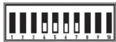
Figure 7
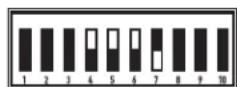
Figure 8

Figure 9
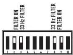
Setting Low Frequency Filters
Each channel has a 12dB per octave Low Frequency filter that can be set on or off. Low impedance models can be set for 33 or 75 Hertz and distributed output ("V" models) for 50 or 75 Hertz to prevent saturation of the 70V speaker transformers. This reduces distortion and prevents amplifier overload. (Figure 10)
- The first channel uses switches 2,3. The second channel uses switches 8,9.
- Switches 3 and 8 turn the LF filter ON or OFF.
- Switches 2 and 9 select 33/75Hz (low Z) or 50/75Hz ("V" models) or 75Hz .
- On four-channel models, the second mode switch has switches for Ch.3 and Ch.4
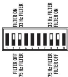
Figure 10
Low Impedance Models: The filter should only be turned off for driving subwooers. The 33Hz setting usually works well with loudspeakers that have large LF drivers (12" or larger). The 75 Hz setting works well with compact (smaller size) loudspeakers. Check the loudspeaker's specifications and select the setting closest to the loudspeaker's low frequency capability.
High Impedance (V^ ) Models: The filter should only be turned off for driving subwoofoers with special low frequency transformers. The 50Hz setting usually works well with high quality speaker transformers. The 75Hz setting works well with speech-grade speakers and transformers.
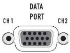
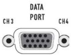
DataPort
Refer to Figure 11.
Two-channel models have one DataPort, four-channel models have two DataPorts (one Ch.1-2, one for Ch.3-4). The DataPort connects to optional QSC accessories and processing devices. DataPort devices provide remote Standby control, monitoring, DSP processing, filter and crossover functions. The CX's DataPort supports the full "V1" DataPort feature set. Two-channel models support directly-mounted DSP "modules". Four channel models require remote mounting of accessory modules connected with DataPort cables.
Each DataPort connects to its respective channel pair; Ch.1-2 or Ch.3-4. Each channel pair may use its DataPort or the Terminal Block inputs. When using the DataPort, do not connect to that channel's Terminal Block inputs. Amplifier Standby is controlled only by the Ch.1-2 DataPort.
DataPort Tips:
- DataPort 1-2 controls Standby for the entire amplifier. The AC switch must be turned ON before the DataPort can control the power.
- Each DataPort controls and monitors the signals to its respective channel pair (Ch.1-2, Ch.3-4).
- Do not use the Bridge Mono or Parallel mode switches when using DataPort Inputs. The signal level may be reduced. For more information, see the Owner's Manual for the DataPort device.
- A DataPort device is normally used to control the signal gain before entering the amplifier. Set the front panel Gain controls at maximum after confirming correct operation. If desired, install the protective cover to prevent tampering.
- Each channel uses a separate internal heat sink. The heat sink temperatures are reported on that pair's DataPort.
- Consult your QSC dealer or the QSC web site for the latest DataPort products.
Inputs
Each channel has a balanced 3-pin terminal block input. Two channel models also feature XLR inputs. The input impedance is 12k ohm balanced or 6k ohm unbalanced. A set of terminal block connectors is included in the carton. Terminal block wiring is connected with simple hand tools, and inputs can be changed quickly. XLR inputs are connected with standard cables and can be changed quickly. Pinouts are marked on the rear panel.
Balanced connections are recommended to reduce AC hum and interference, especially with long cable runs. Unbalanced connections may be suitable for short cables. The signal's source impedance should be less than 600 ohms. If the DataPort is being used for input signals, do not connect cables to the terminal blocks.
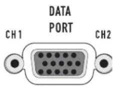
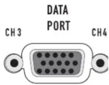
Figure 11
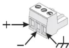
Figure 12
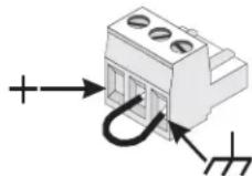
Figure 13
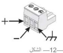
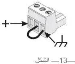
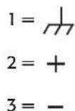
Terminal Block Connectors
Balanced inputs: Strip the wires 14 inch (6mm) and connect to the plug as shown. Be sure to tighten the screws firmly. (Figure 12)
Unbalanced inputs: Strip the wires 14 inch (6mm) and connect to the plug as shown. The middle pin must be connected to the shield pin as shown. Be sure to tighten the screws firmly. (Figure 13)
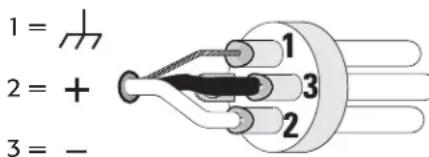
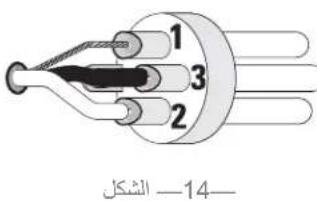
Figure 14
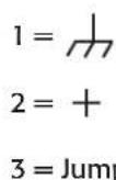
XLR Inputs (2-Ch. models only)
Balanced inputs: Connect to the plug as shown. (Figure 14)
Unbalanced inputs: Connect to the plug as shown. Pin 3 and pin 1 must be connected with a jumper as shown. (Figure 15)
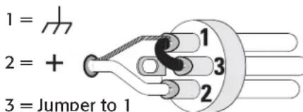
Figure 15
Outputs
Wiring connections are shown on the back of the chassis. Carefully note the polarity marks, which are arranged to make Bridge Mode connections easier. Four-channel models are shown in the examples; two-channel models are similar.

WARNING!: Do not touch output terminals while amplifier power is on. Make all connections with amplifier turned off. Risk of hazardous energy!
Low Impedance Outputs
Stereo and Parallel Mode: Connect each loudspeaker to its own channel of the amplifier, as shown on the chassis label. The mode configuration switches must be set for Stereo or Parallel mode. (Figure 16)
Bridge Mode: Bridge mode configures the channel pair to drive a single high-power loudspeaker load. The mode configuration switches must be set for Bridge mode. Use only the first channel's input and Gain control. Set the second channel's Gain control at minimum. (Figure 17)
Distributed Outputs ("V" models, 70V/140V)
Stereo and Parallel Mode: Connect each 70V circuit to its own channel of the amplifier, as shown on the chassis label. The mode configuration switches must be set for Stereo or Parallel mode. (Figure 18)

WARNING!: 70V Output- Risk of hazardous energy! Use Class 2 wiring for 70V outputs.
Bridge Mode: Bridge mode configures the channel pair to drive a single 140V audio circuit. The mode configuration switches must be set for Bridge mode. Use only the first channel's input and Gain control. Set the second channel's Gain control at minimum. Connect the load as shown on the chassis label. (Figure 19)
140V BRIDGE MODE PRECAUTIONS:

NOTE: Class 3 Wiring shall be used for bridged mono 140V outputs.

NOTE: Connect only 140V distributed audio circuits in bridged mode. Do not use 70V loads in bridge mode! Use Stereo or Parallel mode channels to drive 70V loads. 140V is the minimum for bridge mode operation.
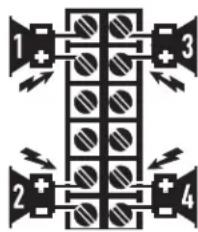
Figure 16
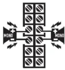
Figure 17
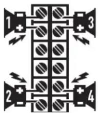
Figure 18
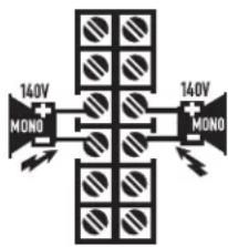
Figure 19
Loads Rated by Model
-Table1-
| Load | CX254 CX3 | 02 CX404 | CX502 CX702 | CX902 CX1 | 102 CX204 | CX302V CX602V CX12 | 02V | |||||||||||||||
| S/P | Br. S/P | Br. S | P Br. | S/P | Br. S/P | Br. S | P Br. | S/P | Br. S/P | Br. S/P | S/P Br. | S/P Br. | S/P Br. | |||||||||
| 2Ω * | * | * | * | * | * | |||||||||||||||||
| 4Ω * | * | * | * | * | * | * | * | * | * | * | * | * | * | |||||||||
| 8Ω * | * | * | * | * | * | * | * | * | * | * | * | * | * | * | * | * | ||||||
| 16Ω | * | * | * | * | * | * | * | * | * | * | * | * | * | * | * | * | * | |||||
| 70 Volt | * | * | * | * | * | |||||||||||||||||
| 140 Volt | * | * | * | * | ||||||||||||||||||
Be sure the model amplifier you are using is rated for the load!
An asterisk (*) indicates the model is rated for the load.
(S / P) = Stereo/Parallel mode (Br.) = Bridge mode
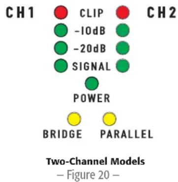
LED Indicators
The LED indicators can be used to monitor system operation and identify common problems. (Figure 20 and Figure 21)
POWER: GREEN, above the BRIDGE (BRDG) and PARALLEL (PAR) indicators.
Normal indication: AC switch ON: LED will illuminate.
If no indication: Check AC power cord and AC outlet. Confirm that DataPort 1-2 is not holding the amp in 'Standby' mode.
CLIP: RED, adjacent the channel number markings.
Normal indication: illuminates whenever the amplifier is driven beyond full power. The resulting distortion corresponds to the brightness of the LED. Distortion that causes only brief flashing may not be audible.
- During muting, the LED fully illuminates. This occurs during normal "On-Off" muting.
Abnormal indication:
- Bright red illumination while the amp is being used indicates either thermal muting or a shorted output.
- If the amplifier overheats, the fan will run at full speed, and operation should resume within one minute. Allow the fan to run, and make sure the amplifier ventilation is adequate.
- A shorted or overloaded output circuit will cause excessive Clip flashing and possible overheating.
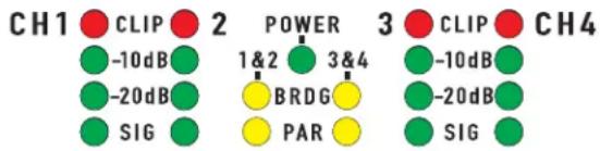
Four-Channel Models
Figure 21
If distortion is audible without a Clip indication, the problem is either before or after the amplifier. Check for damaged speakers or overloaded signal source. The amplifier Gain control should be in the upper half of its range to prevent input overload.
SIGNAL, -20dB, -10dB: GREEN, under each Clip LED.
Normal indication: The SIGNAL indicator illuminates when the input signal exceeds -35 dB, the -20dB indicator illuminates when the signal exceeds -20dB, and the -10dB indicator illuminates when the signal exceeds -10dB.
If no indication: check Gain settings and increase gain if necessary. Check input connections and audio source for signal. If the Clip LED illuminates with little or no Signal indication, check the output wiring for shorts.
Abnormal indication: If the SIGNAL (SIG), -20dB, or -10dB LED illuminates with no signal input, there may be system oscillations or some other malfunction. Disconnect the load and fully reduce the gain. If the LED remains on, the amp may need servicing.
BRDG and PAR (Bridged and Parallel):
Each channel pair has a YELLOW LED for Bridge Mode, and an ORANGE LED for Parallel mode. These show how the rear panel switches are set (see Setting the Mode Switches). In Stereo mode, both LEDs should be OFF.
Gain Controls
Refer to Figure 22 and Figure 23.
The Gain controls are recessed and can be adjusted with a small screwdriver or flat tool. If desired, the Gain Control Security Cover can be installed to prevent changes to the installer's settings.
Turn the gain controls clockwise to increase gain and counter clockwise to decrease gain. The maximum voltage gain of the amplifier varies depending on the model designation. Maximum voltage gain for each model is shown on the front panel label in parentheses adjacent the 0dB attenuation setting.
The Gain controls are marked in dB of attenuation. There are 21 detents for repeatable adjustments. The upper 14 steps are about 1 dB each, and settings should normally be made within this range. The range below -14 dB should not be used for normal program levels, as the input headroom could be exceeded, but can be used for testing at reduced levels. At the minimum setting, the signal is completely cut off.
Gain Control Security Plate
The cover blocks access to the Gain settings. The LED indicators are still visible to monitor the system's operation.
- Use a 9/64" or 3.5mm hex driver to loosen the screw several turns. Do not remove it completely.
- Slide the right end of the cover under the loosened screw.
- Insert the left end tabs into the last row of ventilation slots, and slide the panel fully to the right. It should lock into the slots.
- Confirm that the LED's are visible through the cover. Tighten the hex screw carefully.
Two-Channel Models
Figure 22
Four-Channel Models
Figure 23

Figure 24
Thermal Loss Table
Table 2 provides typical thermal loss in BTU/hr. and kcal/hr. for each model as a function of load and output power level.
- 1/8 power (pink noise) represents typical program with occasional clipping. Use this rating for most applications.
1/3 power (pink noise) represents severe program with heavy clipping.
Full power (sine) are continuous sine wave driven at 1% clipping. - Thermal or overcurrent cutback limits duration of full power 2 Ohm operation.
Idle 1/8 Power
1/3 Power
(pink noise)
(pink noise)
Full Power
(sine)
-Table 2-
| Model Load | BTU/Hr kcal/hr BTU/Hr kcal/hr BTU/Hr kcal/hr kcal/hr kcal/hr | ||||||||
| CX204V 70V (x4) 140 35 1740 440 2605 655 1355 340 | |||||||||
| CX254 | 8 Ω (x2) | 115 | 30 | 1135 | 285 | 1450 | 365 | 1340 | 340 |
| 4 Ω (x2) | 115 | 30 | 1810 | 455 | 2380 | 600 | 2235 | 565 | |
| 2 Ω (x2) | 115 | 30 | 3085 | 780 | 4435 | 1120 | 5265 | 1325 | |
| CX302 | 8 Ω (x2) | 200 | 50 | 565 | 145 | 720 | 180 | 715 | 180 |
| 4 Ω (x2) | 200 | 50 | 995 | 250 | 1245 | 315 | 1295 | 325 | |
| 2 Ω (x2) | 200 | 50 | 1740 | 440 | 2255 | 570 | 2425 | 610 | |
| CX302V 70V (x2) 200 | 50 1125 285 1295 325 | 108 270 | |||||||
| CX404 | 8 Ω (x2) | 120 | 30 | 1570 | 395 | 2145 | 540 | 1975 | 495 |
| 4 Ω (x2) | 120 | 30 | 2560 | 345 | 3370 | 850 | 4060 | 1025 | |
| CX502 | 8 Ω (x2) | 165 | 40 | 910 | 230 | 1130 | 285 | 1090 | 275 |
| 4 Ω (x2) | 165 | 40 | 1570 | 395 | 1945 | 490 | 1875 | 475 | |
| 2 Ω (x2) | 165 | 40 | 2560 | 645 | 3470 | 875 | 3585 | 905 | |
| CX602V 70V (x2) 165 40 1785 450 2260 570 2055 520 | |||||||||
| CX702 | 8 Ω (x2) | 200 | 50 | 790 | 200 | 1080 | 275 | 1245 | 315 |
| 4 Ω (x2) | 200 | 50 | 1310 | 330 | 1910 | 480 | 2230 | 585 | |
| 2 Ω (x2) | 200 | 50 | 2255 | 570 | 3190 | 805 | 4610 | 1160 | |
| CX902 | 8 Ω (x2) | 220 | 55 | 900 | 225 | 1415 | 335 | 1705 | 430 |
| 4 Ω (x2) | 220 | 55 | 1525 | 385 | 2560 | 645 | 3070 | 775 | |
| 2 Ω (x2) | 220 | 55 | 2305 | 580 | 4265 | 1075 | 5385 | 1470 | |
| CX1102 | 8 Ω (x2) | 225 | 57 | 1195 | 300 | 1760 | 445 | 2050 | 515 |
| 4 Ω (x2) | 225 | 57 | 2135 | 540 | 2335 | 590 | 3755 | 945 | |
| 2 Ω (x2) | 225 | 57 | 3975 | 1000 | |||||
| CX1202V 70V (x2) 200 | 200 | 50 | 2175 | 550 | 2605 | 655 | 4230 | 1065 | |
Current Draw Table (in Amperes)
Table 3 provides typical current draw for each model as a function of load and output power level. Units of measurement are Amperes r.m.s.

NOTE: Current draw shown is for 120 VAC line. For 230 VAC models, multiply values shown by 0.5 .
- 1/8 power (pink noise) represents typical program with occasional clipping. Use this rating for most applications.
1/3 power (pink noise) represents severe program with heavy clipping.
Full power (sine) is continuous sine wave driven at 1% clipping. - Thermal or overcurrent cutback limits duration of full power 2 Ohm operation.
-Table3-
| Model Load Idle | 1/8 Power (pink noise) | 1/3 Power (pink noise) | Full Power (sine) | |
| CX204V 70V (x4) | 0.8 7.7 12.1 14.0 | |||
| CX254 8 Ω (x2) | 0.7 | 5.8 | 8.8 | 14.8 |
| 4 Ω (x2) | 0.7 | 9.2 | 14.2 | |
| 2 Ω (x2) | 0.7 | 14.3 | 24.0 | |
| CX302 8 Ω (x2) | 0.8 | 3.8 | 5.4 | 8.4 |
| 4 Ω (x2) | 0.8 | 6.0 | 8.9 | |
| 2 Ω (x2) | 0.8 | 9.6 | 14.3 | |
| CX302V 70V (x2) | 0.8 5.7 8.0 16.0 | |||
| CX404 8 Ω (x2) | 0.7 | 8.1 | 12.2 | 22.0 |
| 4 Ω (x2) | 0.7 | 12.4 | 19.3 | |
| CX502 8 Ω (x2) | 0.9 | 5.6 | 8.0 | 12.5 |
| 4 Ω (x2) | 0.9 | 9.0 | 13.3 | |
| 2 Ω (x2) | 0.9 | 14.0 | 21.0 | |
| CX602V 70V (x2) | 0.9 8.7 13.0 21.0 | |||
| CX702 8 Ω (x2) | 0.9 | 5.0 | 8.4 | 15.8 |
| 4 Ω (x2) | 0.9 | 7.9 | 13.5 | |
| 2 Ω (x2) | 0.9 | 11.8 | 22.0 | |
| CX902 8 Ω (x2) | 0.9 | 6.0 | 11.0 | 20.0 |
| 4 Ω (x2) | 0.9 | 9.5 | 17.0 | |
| 2 Ω (x2) | 0.9 | 14.0 | 27.0 | |
| CX1102 | 8 Ω (x2) | 0.9 | 7.6 | 13.1 |
| 4 Ω (x2) | 0.9 | 11.6 | 20.0 | |
| 2 Ω (x2) | 0.9 | 16.6 | ||
| CX1202V | 70V (x2) 0.9 | 12.0 19.0 39.0 | ||

Specifications
4-Channel Low-Impedance Models
CX254 CX404
| Output Power (Watts) | ||
| 20 - 20k Hz, 0.03% THD, 8 Ohms/Ch. 170 250 | ||
| 20 - 20k Hz, 0.05% THD, 4 Ohms/Ch. 250 | ||
| 1k Hz, 1.0% THD (EIA), 8 Ohms/Ch. | ||
| 1k Hz, 1.0% THD (EIA), 4 Ohms/Ch. 450 | ||
| 1k Hz, 1.0% THD (EIA), 2 Ohms/Ch. 450 | ||
| Bridge Mono, 20 - 20k Hz, 0.1% THD, 16 Ohms 340 500 | ||
| Bridge Mono, 20 - 20k Hz, 0.1% THD, 8 Ohms 500 | ||
| Bridge Mono, 1k Hz, 1.0% THD, 8 Ohms 900 | ||
| Bridge Mono, 1k Hz, 1.0% THD, 4 Ohms 900 | ||
| Distortion, SMPTE-IM <0.01% <0.01% | ||
| Frequency Response | 20 - 20k Hz, ±0.2dB at 10dB below rated output power, all models (-3dB points: 8 Hz and 100 kHz) | |
| Signal To Noise, Unweighted, 20 - 20K Hz | -106 dB -106 dB | |
| Voltage Gain | 29.0x (29dB) | 36.5x (31dB) |
| Input Sensitivity, Vrms | ||
| For Rated Power Into 8 Ohms | 1.28 (+4.4dBu) | 1.22 (+3.9dBu) |
| For Rated Power Into 4 Ohms | 1.08 (+2.9dBu) | EIA: 1.16 (+3.5dBu) |
| Output Circuit Type | AB | AB |
| Input Impedance | 6k ohms unbalanced, 12k ohms balanced, all models | |
| Dynamic Headroom | 2 dB at 4 Ohms, all models | |
| Damping Factor | >500 at 8 Ohms, all models | |
| Amplifier Protection | Short circuit, open circuit, thermal, ultrasonic and RF protection. Stable into reactive or mismatched loads | |
| Cooling Continuously variable speed fan; back-to-front air flow through heat sink tunnel | ||
| Controls | ||
| Front | AC POWER switch, gain controls (1 control per channel, 21 detents) | |
| Back | 10-position DIP switch (1 per channel pair) with Clip Limiter (1 per Ch.), LF Filter on/off (1 per Ch.) LF filter select: 33 or 50 Hz (1 per Ch.), Stereo/Parallel/Bridge mode selection switches (1 set per Ch. pair) | |
| Led Indicators | POWER (green, 1 each), SIGNAL, -10dB, -20dB (green, 1 each per Ch.), CLIP (red, 1 each per channel), BRDG and PAR (yellow, 1 each per Ch. pair) | |
| Connectors | ||
| Input | 3-pin terminal block ("euro" or "Phoenix" type) | |
| Output | barrier strip connectors with protective shroud, one barrier trip per Ch. pair | |
| Other | two QSC DataPort connectors (supports full "V1" feature set), one DataPort per Ch. pair | |
| Load Protection | Turn-on/turnoff muting, AC coupling (DC fault blocking), Clip limiting. | |
| Power Requirements | Refer to rear panel serial number label. Configured at factory for 100, 120 or 220-240 VAC, 50- 60 Hz. | |
| Dimensions | 19.0" (48.3 cm) W, 3.5" (8.9 cm) H, 14" (35.6 cm) D (from front mounting rails, including rear support ears) | |
| Weight | 21 pounds (9.5 kg) net; 27 pounds (12.3 kg) shipping | |
2-Channel Low-Impedance Models
CX302 CX502 CX702 CX902 CX1102
| Output Power (Watts) | |||||
| 20 - 20k Hz, 0.03% THD, 8 Ohms/Ch. 200 300 425 550 700 | |||||
| 20 - 20k Hz, 0.05% THD, 4 Ohms/Ch. 325 500 700 900 1100 | |||||
| 1k Hz, 1.0% THD (EIA), 8 Ohms/Ch. 215 325 475 625 | |||||
| 1k Hz, 1.0% THD (EIA), 4 Ohms/Ch. 375 550 825 1050 | |||||
| 1k Hz, 1.0% THD (EIA), 2 Ohms/Ch. 600 800 1200 1500 1700 | |||||
| Bridge Mono, 20 - 20k Hz, 0.1% THD, 16 Ohms 400 600 850 1100 1400 | |||||
| Bridge Mono, 20 - 20k Hz, 0.1% THD, 8 Ohms 700 1000 1500 2000 | |||||
| Bridge Mono, 1k Hz, 1.0% THD, 8 Ohms | |||||
| Bridge Mono, 1k Hz, 1.0% THD, 4 Ohms 1200 1600 2400 3000 3400 | |||||
| Distortion, SMPTE-IM | <0.01% | <0.01% | <0.02% | <0.02% | <0.02% |
| Frequency Response | 20 - 20k Hz, ±0.2dB at 10dB below rated output power, all models (-3dB points: 8 Hz and 100 kHz) | ||||
| Signal To Noise, Unweighted, 20 - 20K Hz | -106 dB | -107 dB | -106 dB | -104 dB | -106 dB |
| Voltage Gain | 31.5x (30dB) | 40.0x (32dB) | 50.5x (34dB) | 56.6x (35dB) | 56.6x (35dB) |
| Input Sensitivity, Vrms | |||||
| For Rated Power Into 8 Ohms | 1.26 (+4.2dBu) | 1.23 (+4.0dBu) | 1.16 (+3.5dBu) | 1.17 (+3.6dBu) | 1.35 (+4.8dBu) |
| For Rated Power Into 4 Ohms | 1.14 (+3.4dBu) | 1.12 (+3.2dBu) | 1.05 (+2.6dBu) | 1.06 (+2.7dBu) | 1.17 (+3.6dBu) |
| Output Circuit Type | AB | AB | H | H | H |
| Input Impedance | 6k ohms unbalanced, 12k ohms balanced, all models | ||||
| Dynamic Headroom | 2 dB at 4 Ohms, all models | ||||
| Damping Factor | >500 at 8 Ohms, all models | ||||
| Amplifier Protection | Short circuit, open circuit, thermal, ultrasonic and RF protection. Stable into reactive or mismatched loads | ||||
| Cooling | Continuously variable speed fan; back-to-front air flow through heat sink tunnel | ||||
| Controls | |||||
| Front | AC POWER switch, gain controls (1 control per channel, 21 detents) | ||||
| Back | 10-position DIP switch with Clip Limiter (1 per Ch.), LF Filter on/off (1 per Ch.) LF filter select: 33 or 50 Hz (1 per Ch.), Stereo/Parallel/Bridge mode selection switches | ||||
| Led Indicators | POWER (green, 1 each), SIGNAL, -10dB, -20dB (green, 1 each per Ch.), CLIP (red, 1 each per channel), BRDG and PAR (yellow, 1 each) | ||||
| Connectors | |||||
| Input | 3-pin terminal blocks ("euro" or "Phoenix" type) and XLRs (pin 2 positive) | ||||
| Output | barrier strip connectors with protective shroud | ||||
| Other | QSC DataPort connector (supports full "V1"feature set) | ||||
| Load Protection | Turn-on/turnoff muting, AC coupling (DC fault blocking), Clip limiting. | ||||
| Power Requirements | Refer to rear panel serial number label. Configured at factory for 100, 120 or 220-240 VAC, 50-60 Hz. | ||||
| Dimensions | 19.0" (48.3 cm) W, 3.5" (8.9 cm) H, 14" (35.6 cm) D (from front mounting rails, including rear support ears) | ||||
| Weight | 21 pounds (9.5 kg) net; 27 pounds (12.3 kg) shipping | ||||
2- and 4-Channel Distributed 70V Line Models
CX204V CX302V CX602V CX1202V
| Output Power (Watts) | |||
| 20 - 20k Hz, 0.03% THD, 70V/Ch. 200 200 400 800 | |||
| 20 - 20k Hz, 0.03% THD, 8 Ohms/Ch. 550 700 | |||
| 20 - 20k Hz, 0.05% THD, 4 Ohms/Ch. 1100 | |||
| 1k Hz, 0.05% THD (EIA), 70V/Ch. 220 250 440 1000 | |||
| 1k Hz, 0.1% THD (EIA), 70V/Ch. 300 600 1200 | |||
| 1k Hz, 1.0% THD (EIA), 70V/Ch. 300 | |||
| Bridge Mono, 140V, 20 - 20k Hz, 0.1% THD 400 400 800 850 | |||
| Bridge Mono, 140V, 1k Hz, 0.1% THD 440 600 1200 2400 | |||
| Bridge Mono, 1k Hz, 0.1% THD, 16 Ohms 1200 1400 | |||
| Bridge Mono, 1k Hz, 0.1% THD, 8 Ohms 2300 | |||
| Distortion, SMPTE-IM <0.02%, all models | |||
| Frequency Response 20 - 20k Hz, ±0.2dB at 10dB below rated output power, all models (-3dB points: 8 Hz and 100 kHz) | |||
| Signal To Noise, Unweighted, 20 - 20K Hz | -106 dB. all models | ||
| Voltage Gain | 56.6x (35dB) all models | ||
| Input Sensitivity, Vrms | 1.26V (+4.2dBu) for rated power at 70.7V | ||
| Output Circuit Type | AB AB AB H | ||
| Input Impedance | 6k ohms unbalanced, 12k ohms balanced, all models | ||
| Dynamic Headroom | 2 dB at 4 Ohms, all models | ||
| Damping Factor | >500 at 8 Ohms, all models | ||
| Amplifier Protection | Short circuit, open circuit, thermal, ultrasonic and RF protection. Stable into reactive or mismatched loads | ||
| Cooling | Continuously variable speed fan; back-to-front air flow through heat sink tunnel | ||
| Controls | |||
| Front | AC POWER switch, gain controls (1 control per channel, 21 detents) | ||
| Back | 10-position DIP switch with Clip Limiter (1 per Ch.), LF Filter on/off (1 per Ch.) LF filter select: 33 or 50 Hz (1 per Ch.), Stereo/Parallel/Bridge mode selection switches | ||
| Led Indicators | POWER (green, 1 each), SIGNAL, -10dB, -20dB (green, 1 each per Ch.), CLIP (red, 1 each per channel), BRDG and PAR (yellow, 1 each) | ||
| Connectors | |||
| Input | 3-pin terminal blocks ("euro" or "Phoenix" type)and XLRs (pin 2 positive) | ||
| Output | barrier strip connectors with protective shroud | ||
| Other | QSC DataPort connector (supports full "V1"feature set) | ||
| Load Protection | Turn-on/turnoff muting, AC coupling (DC fault blocking), Clip limiting. | ||
| Power Requirements | Refer to rear panel serial number label. Configured at factory for 100, 120 or 220-240 VAC, 50- 60 Hz. | ||
| Dimensions | 19.0" (48.3 cm) W, 3.5" (8.9 cm) H, 14" (35.6 cm) D (from front mounting rails, including rear support ears) | ||
| Weight | 21 pounds (9.5 kg) net; 27 pounds (12.3 kg) shipping | ||
Specifications are subject to change without notice.
QSC
Mailing Address:
QSC Audio Products, LLC
1675 MacArthur Boulevard
Costa Mesa, CA 92626-1468 USA
Telephone Numbers:
Main Number: (714) 754-6175
Sales & Marketing: (714) 957-7100 or toll free (USA only) (800) 854-4079
Customer Service: (714) 957-7150 or toll free (USA only) (800) 772-2834
Facsimile Numbers:
Sales & Marketing FAX: (714) 754-6174
Customer Service FAX: (714) 754-6173
World Wide Web:
www.qscaudio.com
E-mail:
info@qscaudio.com
service@qscaudio.com
Serie CX
Guía del usuario
QSC Audio Products, LLC
1675 MacArthur Boulevard
service@qscaudio.com
QSC Audio Products, LLC
1675 MacArthur Boulevard
service@qscaudio.com
Serie CX
Bedienungsanleitung
QSC Audio Products, LLC
1675 MacArthur Boulevard
Costa Mesa, CA 92626-1468 USA
Telefonnummern:
service@qscaudio.com
CX系列
用户指南
2通道低阻抗型:
CX302
CX502
CX702
CX902
CX1102
4通道低阻抗型:
CX254
CX404
70伏直接输出型:
CX204V(4通道)
CX302V(2通道)
CX602V(2通道,8欧姆)
CX1202V(2通道,4和8欧姆)
符号说明
QSC Audio Products, LLC
1675 MacArthur Boulevard
Costa Mesa, CA 92626-1468 USA
电话号码:
总机:(714) 754-6175
service@qscaudio.com
70 1
(4) CX204V
(204V CX204V
(8.8.12) CX602V
(8.4CX1202V
Cglggejagallagellaaia
CX254
CX404
yjbjg jbjg jbjg jbjg
CX302
CX502
CX702
CX902
CX1102

AR
jg 2
y 1
aallll lll lss sdd aad aagaae aae aee aee aee aee aee aee aee aee
1
aagall aalil yllglal gai (la) "NOTE" glaae pia
g 111111111111111111111111111111
Jg 10000000000000000000000000000000000000000000

aL

y 1

Lulukill 0j
:!
Jie 11
.
aaii aiee aee aie
A
sall (gsslll) gai jai gai gai gai gai gai gai gai gai gai
y j 1 1 1 1 1 1 1 1 1 1 1 1 1 1 1 1 1 1 1 1 1 1 1 1 1 1
a
a 1
aill 1
a 1
J 1
Aa
a a a a a a a a a a a a a a a a a a a a a a a a a a a a
jog 100000000000000000000000000000000000000000000000000000000000000
y
aallll allll g k jy jy glk y k l jn aai ai ay d s i ay d s i ay d s i ay
(FCC)
a 15e aaiy
NOTE :

g jy 1 y 1 1 1 1 1 1 1 1 1 1 1 1 1 1 1 1 1 1 1 1 1 1 1 1 1 1
A
aill gylg yol j
aiall jalll jaiilall aaiail lalil
aall juaall ait g sji jjia jia jia jia
www.qsc.com Jc aagall UgauuQSC aJU gagall oju jq QSCjolalgdoaall jao
U
L 1
J 1
Cgge Lxaggl xalalj j 100000000000000000000000000000QSC, QSC J
y 1
y.
a
daii daii g jnssll aaiil lalai i 10 QSC s s
:CX jlll
70 1 j 1 1 1 1 1 1 1 1 1 1 1 1 1
A. julalai, 12iag iiai ci gaii j s
QSCJ 1 aaii aaiia iaiia iaiia iaiia iaiia iaiia iaiia
yjglalldxallgdsll jall jil jaiia jaiai jaoaai aai
jllg jglg jglg QSC 1
.
XLR
.
aalal gaii aal alil
10-20 20- g jg jg jg jg jg jg jg jg jg jg
A
(204 100,70,25 CX302JJLIT-42 J
#
.CX 1
.
.(Jolalgai aaiai jut ciaibil)aaii aaijallao
3 15 yai aegay gao jia Lua
aaii
y 1
gall sJiaie gaiwll gaii
1-1
aall aaiial ayilil caiail ai jia 4
- · = 0
J 5
2
J 6
3
aai 1
(xLR 2CX404)
1-2
jolaljoljoljoljoljolj.5
CH1 jbjj 2000
2yjllc0gJzJzJzJz.6
caliliiisia Jua 2
zgl zlaa jaiy jgj.7
CH2i jbi aie gaojia 32jia Jiu
a 8
E
gall gall jalal jalal jalal jalal jalal jalal jalal jalal jalal jalal jalal jalal jalal jalal jalal jalal jalal jalal jalal jalal jalal jalal jalal jalal jalal jalal jalal j
3
J 1 J 1 J 1 J 1 J 1 J 1 J 1 J 1 J 1 J 1 J 1 J 1 J 1 J 1 J 1 J 1 J 1 J 1 J 1 J 1 J 1 J 1 J 1 J 1 J 1 J 1 J 1 J 1 J 1 J 1 J 1 J 1 J 1 J 1 J
1 1

AR
JS : QJ - 4 -
a
1.
2
Jbllg aagab g 2e gacal abai paaill jll
NOTE :

i j k l m n o p q r s t
y


OFF OFF 75Hz STEREO OFF 75Hz OFF
5
6-11 6
e
(CX404V jbrjg) 5
(LF) 2ill aiaiaiaiaiaai, ai j Sj glaall jnaalll gai aliaiaiaiaiaiaiaai:
sall s jlll gll l 1
Jae jaiy Saiy lai 21 giall Jae gai Laiy saiy liaiia y: ciig qiy dojg all jil
4,32,1j jjj j j j 4,3
cblall 1220 b
a 6
aal 1 (jaiy) aaiy jaiy g aiay
10
Jg j g j g j g j g j g j g j g j g
J.S.7-7
J. 31 8
J-9
FILER OFF FILER OFF 54 HZ FILTER
PONNNNNE
F 5545
10
j 4 1
7,6,5,4 1 j k b u p i. kia o jy I gio Jp suiu Juy, aiaa o j y jia 8i (7)
a 6,5,4 10
J 74.56
y jil y jil jil jil jil jil jil jil jil jil jil jil jil jil jil jil jil jil jil jil jil jil jil jil jil jil jil jil jil jil jil jil jil jil jil jil jil jil jil jil jil jil jil jil
j

23 1
12 50 75 33 (10)
9,8 12 2 1
LF 83
75(“V"c1aill) 7550 (uasszll Z) 7533 92 jallal
331 331 331 331 331 331 331 331 331 331 331 331 331 331 331 331 331 331 331 331 331 331 331 331 331 331
50
$$ j _ {k - 1} - 1 1 - $$
Lilil jia
11.5.11 2^n · p^n - 1
1-2 111111111111111111111111111111111111111111
aalal aalal alalal qacgall galsgall 6
#
JxL 12 1
y 600 600
iJbI JIe gao 1
a a a a a a a a a a a a a a a a a a a a a a a a a a a a a a a a a a a a a a a a a a a a a a a a a a a a a a
21 1 14 14 14 14 14 14 14 14 14 14 14 14 14 14 14 14 14 14 14 14
a
gail aill aylll lalall jn ski, gill cie! gialld eall qin
JedSly lee jn 3.5 64/9 1
aill 2
3
a 4
24
s
j 2
181
J31
% 1
2 1
A
()
a1131
(a+b)
(a+b)lll
Jalee jaealal 819
BTU/Hrkcal/hrBTU/Hrkcal/hrkcal/hrkcal/hrBTU/Hrkcal/hr
| 340 | 1340 | 365 | 1450 | 285 | 1135 | 30 | 115 | CX254(2x) Ω 8 |
| 565 | 2235 | 600 | 2380 | 455 | 1810 | 30 | 115 | (2x) Ω 4 |
| 1325 | 5265 | 1120 | 4435 | 780 | 3085 | 30 | 115 | (2x) Ω 2 |
| 180 | 715 | 180 | 720 | 145 | 565 | 50 | 200 | CX302(2x) Ω 8 |
| 325 | 1295 | 315 | 1245 | 250 | 995 | 50 | 200 | (2x) Ω 4 |
| 610 | 2425 | 570 | 2255 | 440 | 1740 | 50 | 200 | (2x) Ω 2 |
| (2x)1425280296836208270 | ||||||||
| 495 | 1975 | 540 | 2145 | 395 | 1570 | 30 | 120 | CX404(2x) Ω 8 |
| 1025 | 4060 | 850 | 3370 | 345 | 2560 | 30 | 120 | (2x) Ω 4 |
| 275 | 1090 | 285 | 1130 | 230 | 910 | 40 | 165 | CX502(2x) Ω 8 |
| 475 | 1875 | 490 | 1945 | 395 | 1570 | 40 | 165 | (2x) Ω 4 |
| 905 | 3585 | 875 | 3470 | 645 | 2560 | 40 | 165 | (2x) Ω 2 |
| CX602V(2x) Φ 701654017854502260 | ||||||||
| 315 | 1245 | 275 | 1080 | 200 | 790 | 50 | 200 | CX702(2x) Ω 8 |
| 585 | 2230 | 480 | 1910 | 330 | 1310 | 50 | 200 | (2x) Ω 4 |
| 1160 | 4610 | 805 | 3190 | 570 | 2255 | 50 | 200 | (2x) Ω 2 |
| 430 | 1705 | 335 | 1415 | 225 | 900 | 55 | 220 | Ω 8 CX902(2x) |
| 775 | 3070 | 645 | 2560 | 385 | 1525 | 55 | 220 | (2x) Ω 4 |
| 1470 | 5385 | 1075 | 4265 | 580 | 2305 | 55 | 220 | (2x) Ω 2 |
| 515 | 2050 | 445 | 1760 | 300 | 1195 | 57 | 225 | CX1102(2x) Ω 8 |
| 945 | 3755 | 590 | 2335 | 540 | 2135 | 57 | 225 | (2x) Ω 4 |
| 1000 | 3975 | 57 | 225 | (2x) Ω 2 |
CX1202V(x2)7020050217555026656
.0.5 230 120 1

aill piall aill pial l. jy jy cie bai y gai kai (ayr jll claiyall) aiall 811
311
% 1
2 1 jll jll jll jll
| الإستعمال(الترجمة) | الإستعمال 311(الترجمة) | الإستعمال 811(الترجمة) | الإستعمال 700.87.712.114.0 | ||
| CX204V(4x) †‡‡ 700.87.712.114.0 | |||||
| 14.8 | 8.8 | 5.8 | 0.7 | (2x) Ω 8 | CX254 |
| 24.0 | 14.2 | 9.2 | 0.7 | (2x) Ω 4 | |
| 38.0 | 24.0 | 14.3 | 0.7 | (2x) Ω 2 | |
| 8.4 | 5.4 | 3.8 | 0.8 | (2x) Ω 8 | CX302 |
| 14.0 | 8.9 | 6.0 | 0.8 | (2x) Ω 4 | |
| 23.0 | 14.3 | 9.6 | 0.8 | (2x) Ω 2 | |
| 16.0 | CX302V(2x) †‡‡ 700.85.7 | ||||
| 22.0 | 12.2 | 8.1 | 0.7 | 8 Ω (x2) | CX404 |
| 38.0 | 19.3 | 12.4 | 0.7 | 4 Ω (x2) | |
| 12.5 | 8.0 | 5.6 | 0.9 | (2x) Ω 8 | CX502 |
| 21.0 | 13.3 | 9.0 | 0.9 | (2x) Ω 4 | |
| 34.0 | 21.0 | 14.0 | 0.9 | (2x) Ω 2 | |
| CX602V(2x) †‡‡ 700.98.713.021.0 | |||||
| 15.8 | 8.4 | 5.0 | 0.9 | (2x) Ω 8 | CX702 |
| 26.0 | 13.5 | 7.9 | 0.9 | (2x) Ω 4 | |
| 42.0 | 22.0 | 11.8 | 0.9 | (2x) Ω 2 | |
| 20.0 | 11.0 | 6.0 | 0.9 | (2x) Ω 8 | CX902 |
| 33.0 | 17.0 | 9.5 | 0.9 | (2x) Ω 4 | |
| 50.0 | 27.0 | 14.0 | 0.9 | (2x) Ω 2 | |
| 25.0 | 13.1 | 7.6 | 0.9 | (2x) Ω 8 | CX1102 |
| 39.0 | 20.0 | 11.6 | 0.9 | (2x) Ω 4 | |
| 16.6 | 0.9 | (2x) Ω 2 |
19.039.0 CX12V(2x) 700.9
g 8 g j 8 g j 8 g j 8 g j 8 g j 8 g j
QSC Audio Products, LLC
1675 MacArthur Boulevard
Costa Mesa, CA 92626-1468 USA
=
(714) 754-6175:
aall (714) 957-7100:
(800) 854-4079 (
dai (714) 957-7150:
(800) 772-2834 (
:
(714) 754-6174:
(714) 754-6173:
:
www.qscaudio.com
1
info@qscaudio.com
service@qscaudio.com