
SPA460 - Receiver QSC - Free user manual and instructions
Find the device manual for free SPA460 QSC in PDF.
| Product Type | Audio Power Amplifier (Receiver) |
| Brand | QSC |
| Model | SPA460 |
| Number of Channels | 4 channels (pair-configurable) |
| Output Power (Stereo) | 60 W per channel at 8 Ω, 60 W at 4 Ω (SPA4-60) |
| Bridge Mode Power | 200 W per pair at 8/4 Ω, 250 W at 70 V, 250 W at 100 V |
| Output Circuit | Class D |
| Frequency Response | 20 Hz - 20 kHz ±0.1 dB |
| Signal-to-Noise Ratio | >100 dB |
| Input Impedance | >10 kΩ (balanced or unbalanced) |
| Input Sensitivity | 1.23 V (+4 dBu) |
| Gain (8 Ω) | 27 dB (SPA4-100) / 25 dB (SPA4-60) |
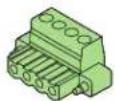
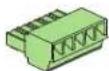
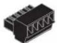
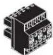
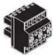
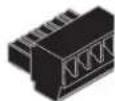
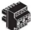
| Input Connectors | Euroblock 3.5 mm, 10-pin (green) |
| Output Connectors | Euroblock 5 mm, 4-pin (green), x2 |
| Remote Control | Euroblock 3.5 mm, 10-pin (black) for 10 kΩ potentiometer and standby |
| Indicators | Power, Signal (green), Limiter/Mute/Protect (red/orange) per channel |
| Power Supply | 100-240 V~, 50-60 Hz, universal with active power factor correction |
| Power Consumption | Not specified, but Energy Star compliant |
| Dimensions (H x W x D) | 43 mm x 220 mm x 241 mm |
| Net Weight | 1.8 kg (4.0 lb) |
| Cooling | Natural convection |
| Operating Temperature | Not specified, but ventilation required |
| Certifications | UL, CE, Energy Star, RoHS/WEEE, FCC Class B, UL 2043 with plenum kit |
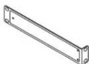
| Box Contents | IEC cable, quick start guide, connectors, 19" rack ears and hardware |
| Maintenance and Cleaning | Clean with a dry, lint-free cloth. Do not use liquids or aerosols. |
| Safety | Observe warning symbols. Do not open the enclosure. Risk of electric shock. |
| Repairability | Contact QSC customer service or an authorized technician. Spare parts available through after-sales service. |
Frequently Asked Questions - SPA460 QSC
User questions about SPA460 QSC
0 question about this device. Answer the ones you know or ask your own.
Ask a new question about this device
Download the instructions for your Receiver in PDF format for free! Find your manual SPA460 - QSC and take your electronic device back in hand. On this page are published all the documents necessary for the use of your device. SPA460 by QSC.
USER MANUAL SPA460 QSC
System Power Amplifier (SPA)
Installation Guide
SPA2-60 Amplifier SPA4-60 Amplifier
SPA2-200 Amplifier SPA4-100 Amplifier
EXPLANATION OF SYMBOLS
The term "WARNING!" indicates instructions regarding personal safety. If the instructions are not followed the result may be bodily injury or death.
The term "CAUTION!" indicates instructions regarding possible damage to physical equipment. If these instructions are not followed, it may result in damage to the equipment that may not be covered under the warranty.
The term "IMPORTANT!" indicates instructions or information that are vital to the successful completion of the procedure.
The term "NOTE" is used to indicate additional useful information.

The intent of the lightning flash with arrowhead symbol in a triangle is to alert the user to the presence of un-insulated "dangerous" voltage within the product's enclosure that may be of sufficient magnitude to constitute a risk of electric shock to humans.

The intent of the exclamation point within an equilateral triangle is to alert the user to the presence of important safety, and operating and maintenance instructions in this manual.
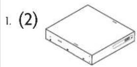
What's in the Box
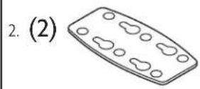
| (1x)SPA2-60SPA2-200SPA4-60SPA4-100 | (1x)AC Power Cord,US | (1x)Rack EarQSC P/NCH-001344-00 | (2x)Joining PlateQSC P/NCH-001345-00 | (2x) |
| (2x)Rack-Ear SpacerQSC P/NCH-001386-00 | (6x)Phillips Pan HeadM4 x 7 mm | (6x)Phillips FlatheadM3 x 6 mm | (6x)Foam SpacerQSC P/NPL-001023-00 | (4x) |
| (1x)Rack-Ear Cover LabelQSC P/NLB-001138-00 | SPA 2-channel (1x)SPA 4-channel (2x)Euro Plug 3.5 mm,4 pos, gmQSC P/NCO-000646-00 | SPA 2-channel (1x)Euro Plug 3.5 mm,5 pos, gmQSC P/NCO-000644-00 | Euro Plug 3.5 mm,4 pos, blkQSC P/NCO-000645-00 | SPA 2-channel (1x)Euro Plug 3.5 mm,4 pos, blkQSC P/NCO-000645-00 |
| SPA 4-channel (1x)Plug 3.5 mm,10 pos, gmQSC P/NCO-000647-00 | SPA 4-channel (1x)Plug 3.5 mm,10 pos, gmQSC P/NCO-000648-00 | WarrantyTD-000453 | (1x)Safety InformationTD-000337 | (1x) |
Installation
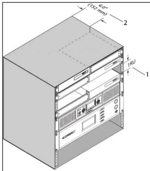
Ventilation
- Recommend 1RU (1.75 in / 44.45 mm) space above the amplifier.
- Minimum open space of 6 inches measured from back of amplifier.

NOTE: QSC System Power Amplifiers contain advanced protection circuitry which allows them to reduce output power in order to maintain safe operating temperatures. Insufficient ventilation may result in the amplifier reducing output power during normal operation (indicated by Limiter/Protect LEDs illuminating red). To reduce the possibility of thermal limiting, and allow proper heat dissipation, we recommend that you keep the space directly above and to the rear of these amplifiers free of obstacles.
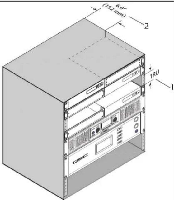
Figure 1
Select the Amplifier Installation Configuration
Choose one of the following configuration options:
A. One Amplifier 19-inch Rack (Left or Right Mount) on page 3 D. Under Table or on Wall on page 4
B. Two Amplifiers 19-inch Rack (Front or Rear Facing Out) on page 3 E. Free-Standing on Desk/Table on page 5
C. One Amplifier Half Rack (Front or Rear Facing Out) on page 4 F. Plenum Installation on page 5
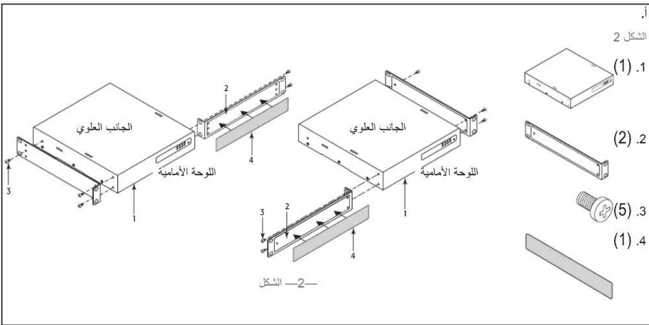
A. One Amplifier 19-inch Rack (Left or Right Mount)
Figure 2
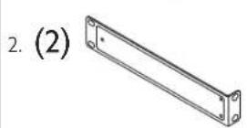
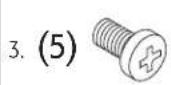
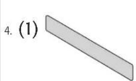
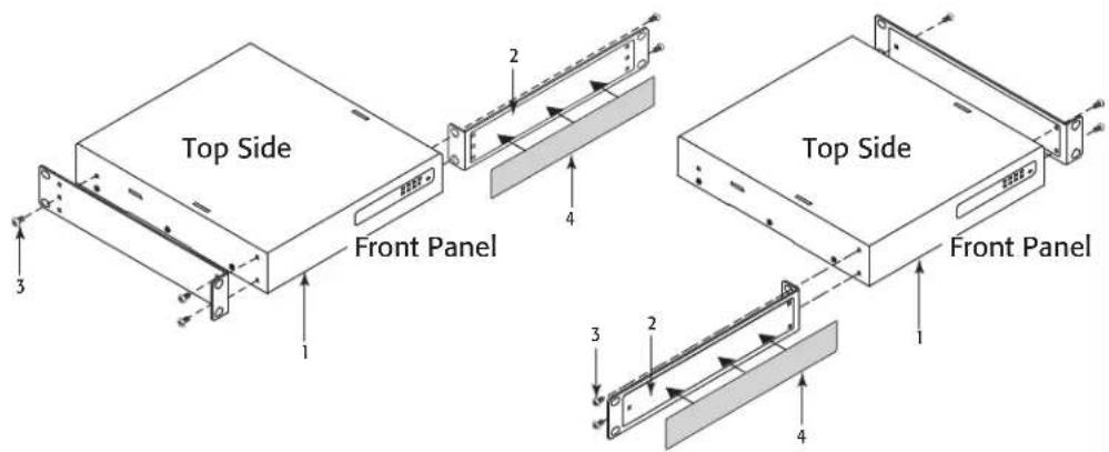
Figure 2
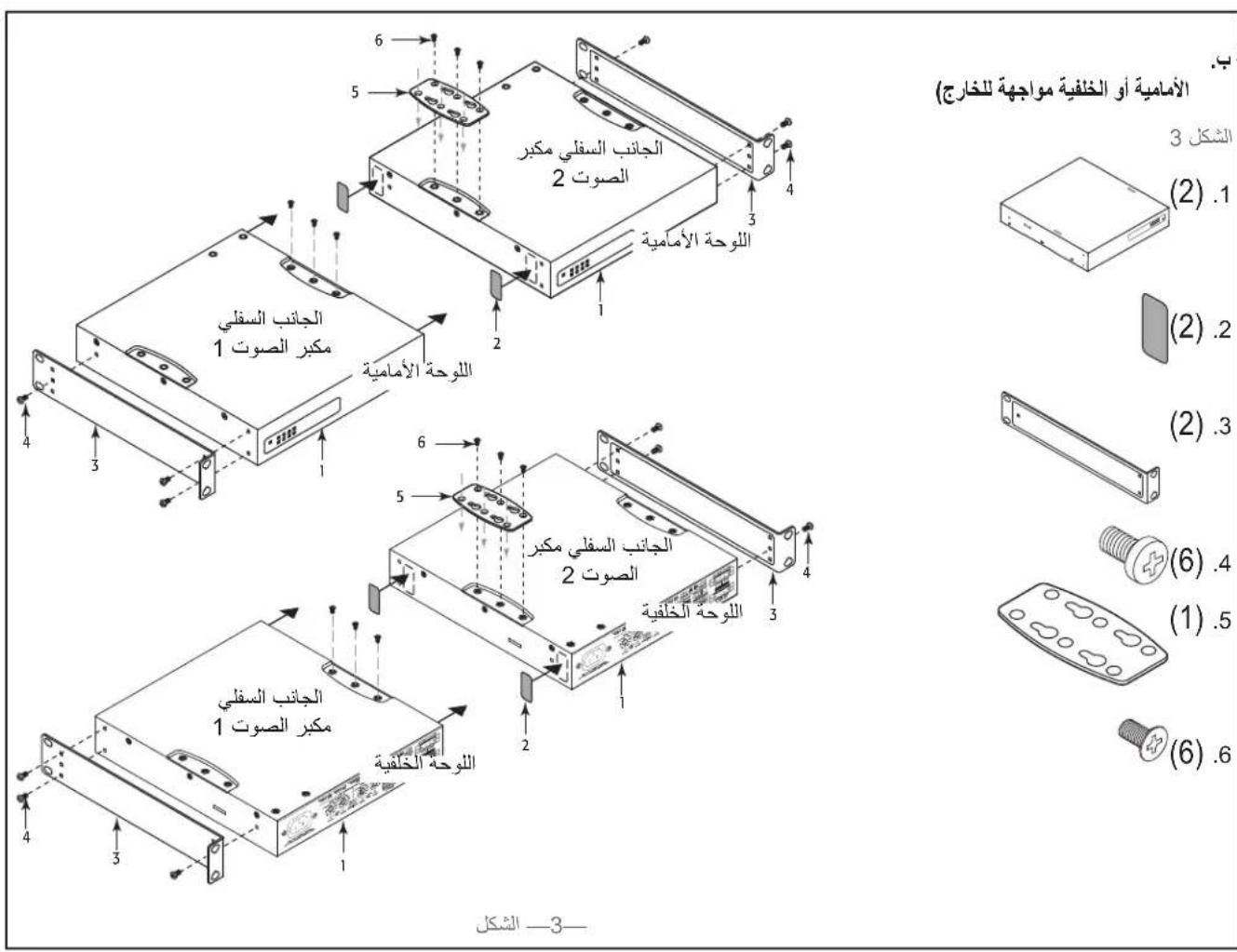
B. Two Amplifiers 19-inch Rack (Front or Rear Facing Out)
Figure 3

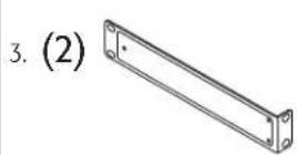
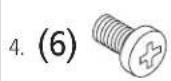
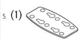
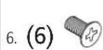
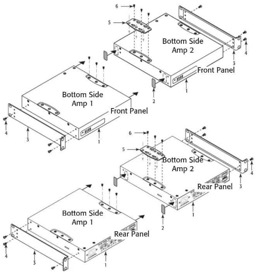
Figure 3

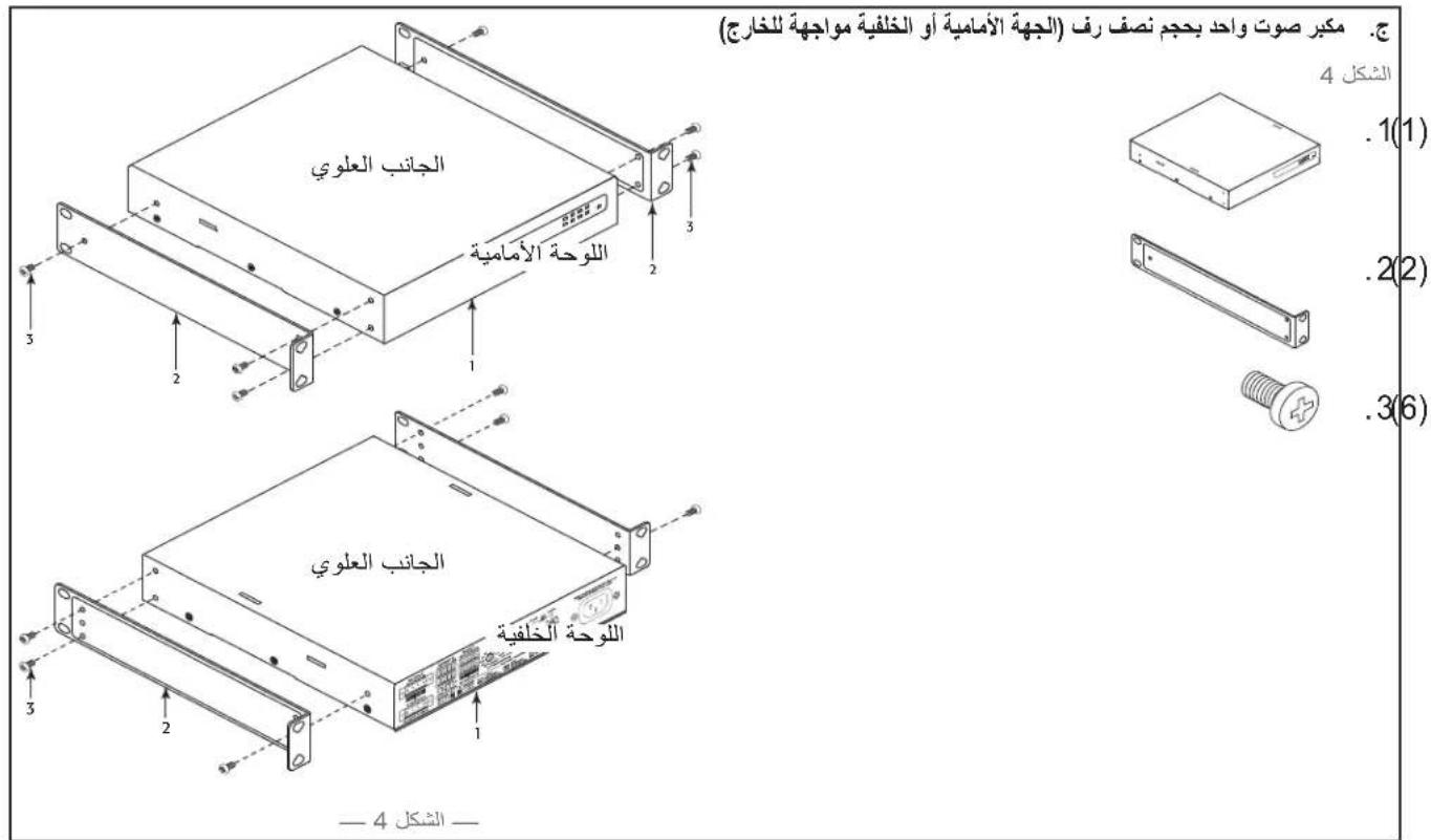
C. One Amplifier Half Rack (Front or Rear Facing Out)
Figure 4
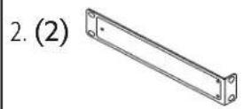
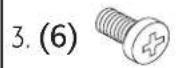
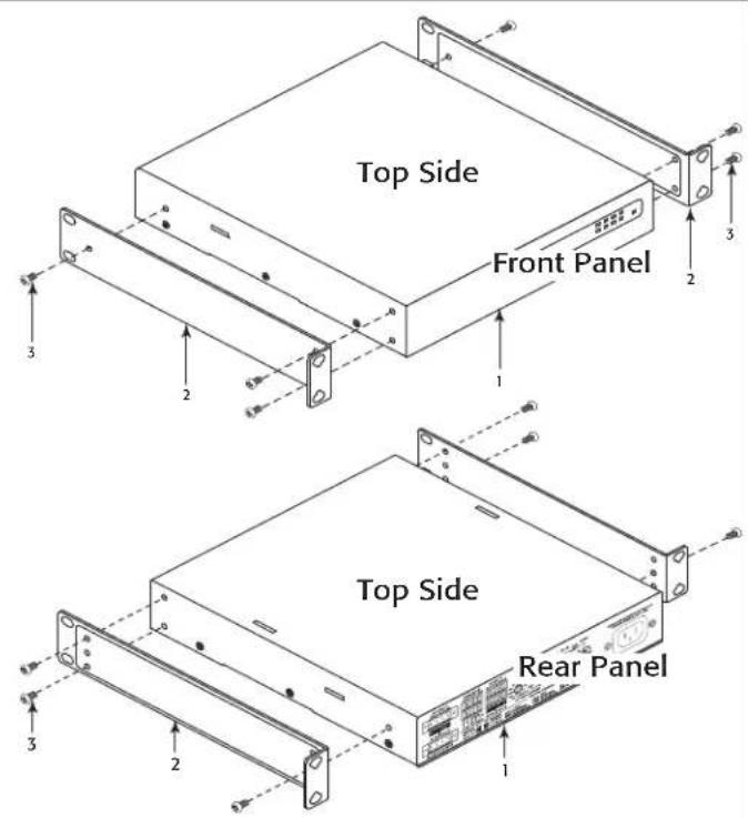
Figure 4
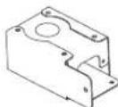
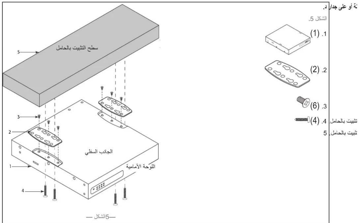
D. Under Table or on Wall
Figure 5.
4. (4) Not supplied - use appropriate screws for mounting surface.
5. Mounting Surface
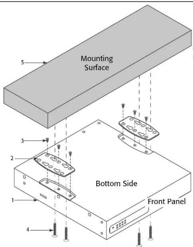
Figure 5
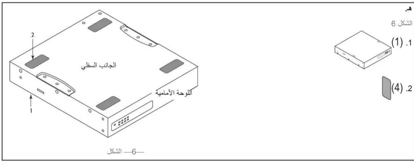
E. Free-Standing on Desk/Table
Figure 6
1. (1)

2. (4)
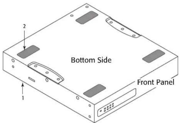
Figure 6
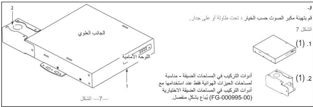
F. Plenum Installation
Configure amplifier per option D Under Table or on Wall.
Figure 7
1. (1)
2. (1)
Plenum Kit - Suitable for Air Handling Spaces only when used with optional Plenum Kit (FG-000995-00) sold separately.
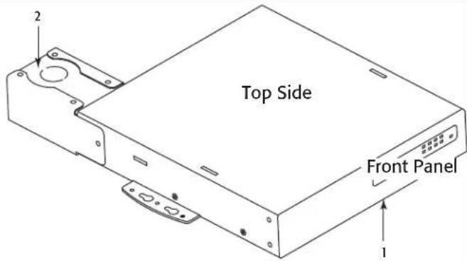
Figure 7
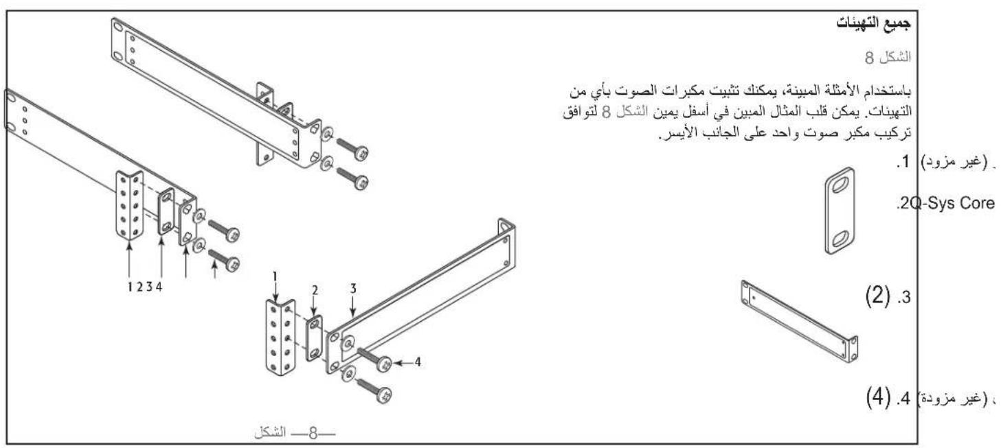
Rack-Mounting Options
All Configurations
Using the examples shown, you can mount any of the amplifier configurations. The example at the lower right of Figure 8 can be flipped to accommodate a single amplifier on the left side.
- Equipment Rack (not supplied)
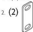
Figure 8
Optional - to bring flush with Q-Sys Core 110
3. (2)
- (4) Rack-Mounting Screws and Washers (not supplied)

Figure 8
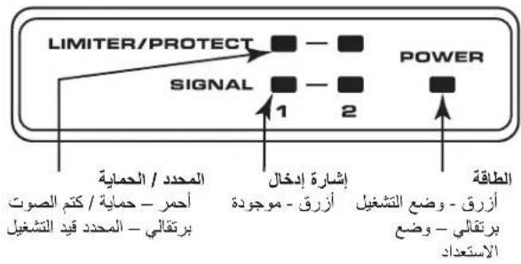
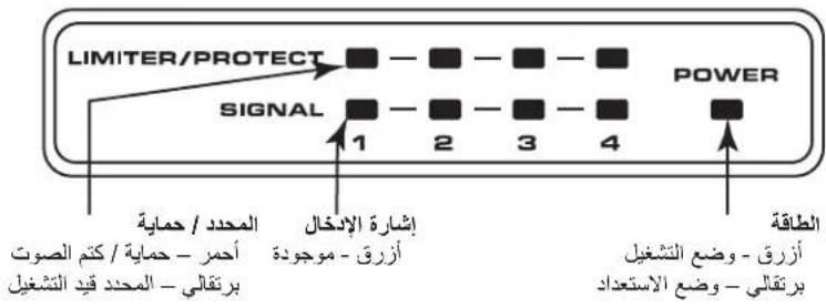
Front Panel
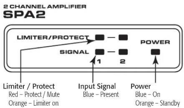
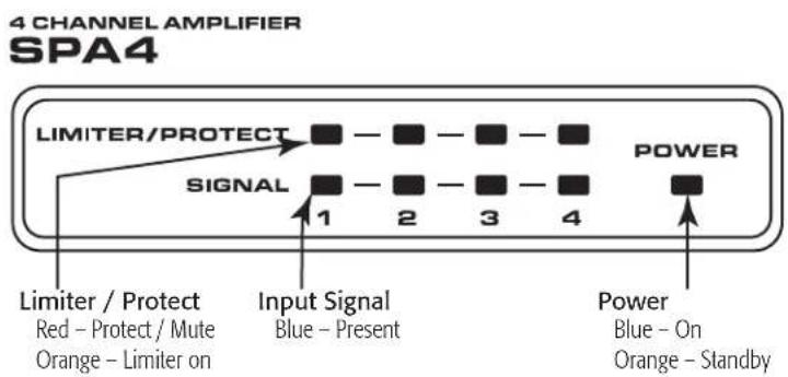
Figure 9
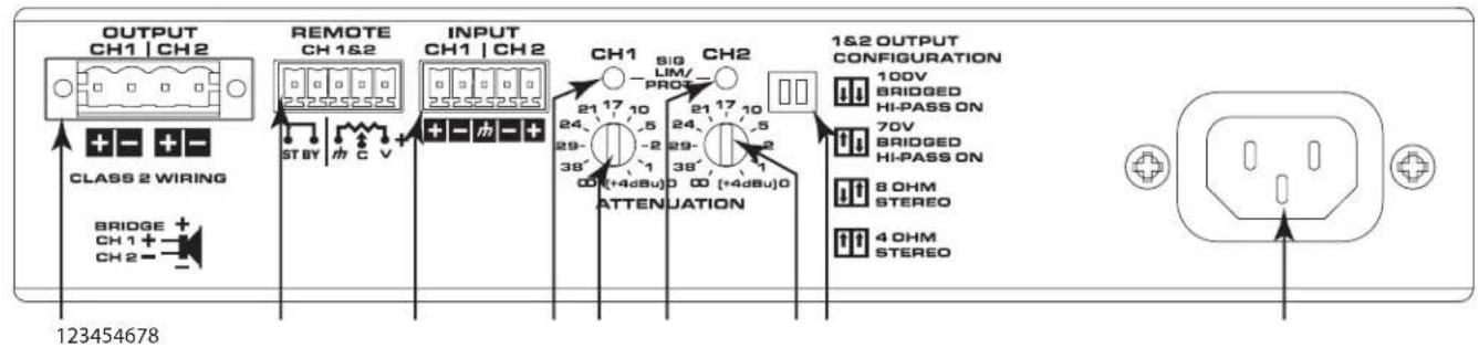
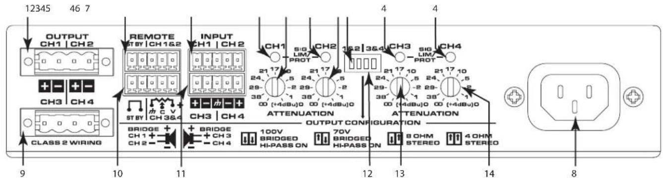
Rear Panel
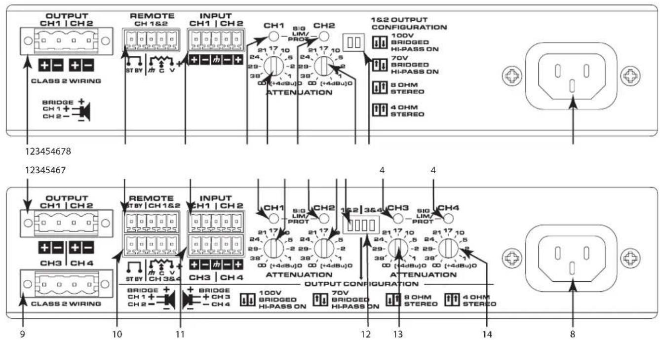
Figure 10
- Output Channels 1 & 2
- Remote Control Channels 1 & 2
- Input Channels 1 & 2
- Channel 1 thru Channel 4 Status LEDs
a. Green - Normal Signal Level
b. Amber - Input or Output Overload/ Clipping or Thermal Limiting
c. Red - Limit or Protect Mode
d. Red - Thermal Limit or Protect Mode
e. Red - Mute
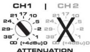
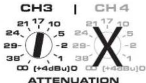
- Channel 1 Attenuator Control
- Channel 2 Attenuator Control
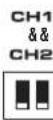
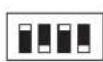
- Mode Configuration Switches Channel 1&2
- AC Power Connection
-
Output Channels 3 & 4
-
Remote Control Channel 3 & 4
- Input Channels 3 & 4
- Mode Configuration Switches Channel 3 & 4
- Channel 3 Attenuator Control
- Channel 4 Attenuator Control
No signal for 10 minutes, amplifier outputs are muted (LEDs are red). No signal for 25 minutes, amplifier is put in Standby Mode (Rear LEDs are off).
Connections
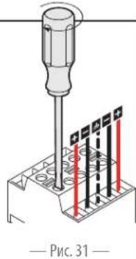
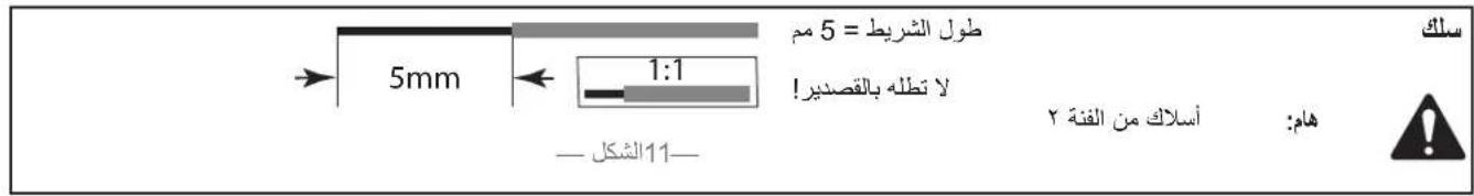
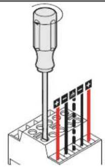
Wire

IMPORTANT: Class 2 Wiring
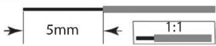
StripLength = 5mm
DO NOT TIN!
Figure 11
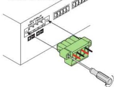
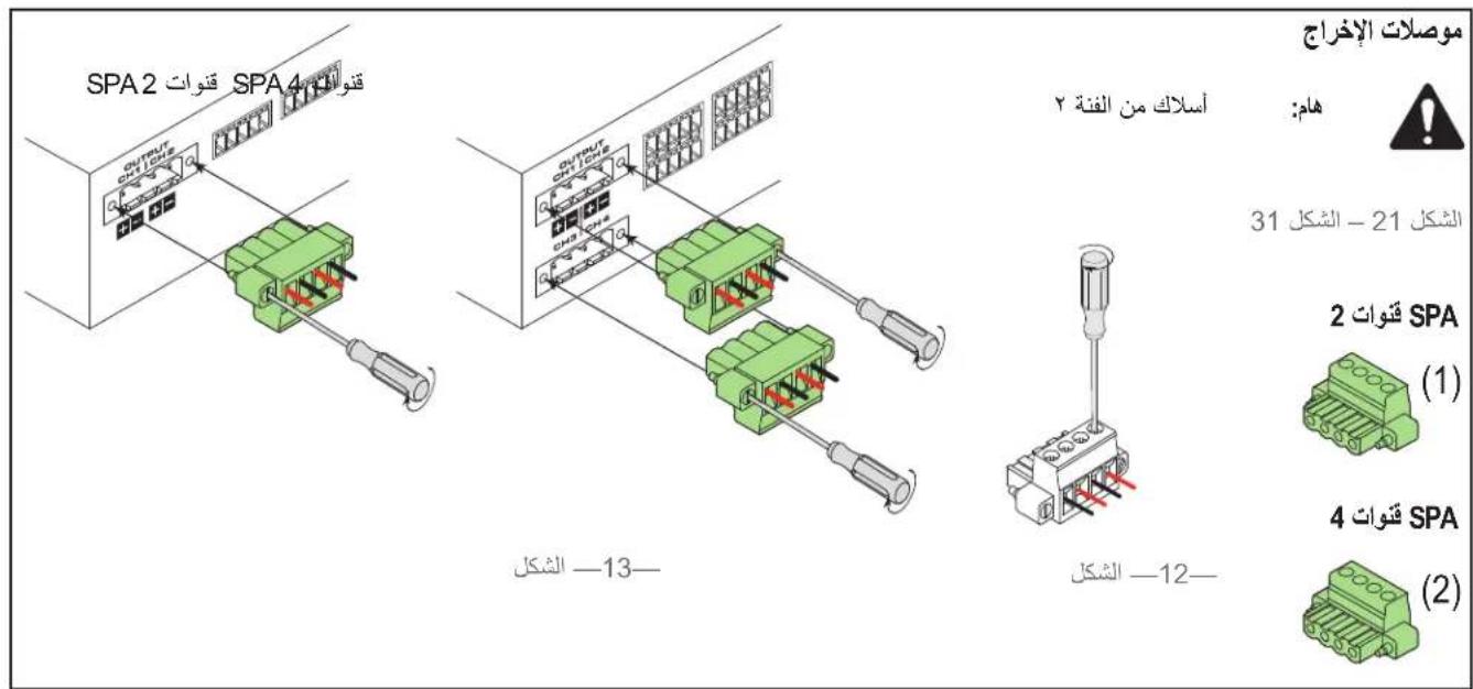
Output Connectors

IMPORTANT: Class 2 Wiring
Figure 12 - Figure 13
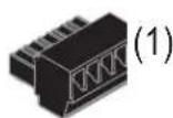
SPA 2-channel
(1)
SPA 4-channel
(2)
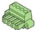
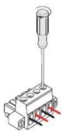
Figure 12
SPA 2-channel
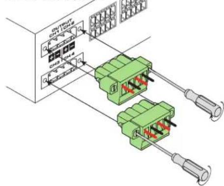
SPA 4-channel
Figure 13
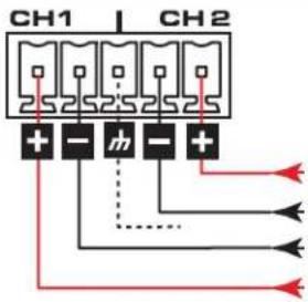
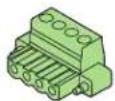
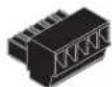
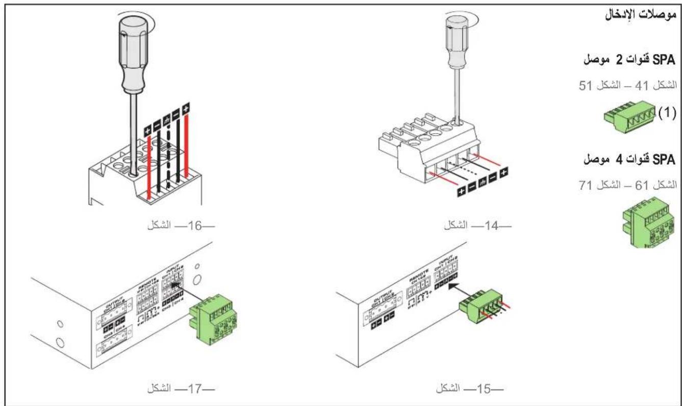
Input Connectors
SPA 2-channel Connector
Figure 14 - Figure 15
(1)
SPA 4-channel Connector
Figure 16 - Figure 17
(1)
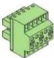
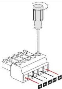
Figure 14
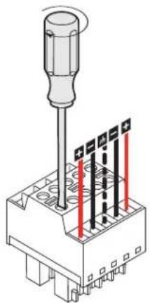
Figure 16
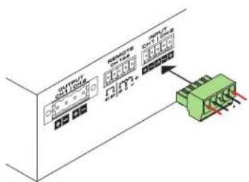
Figure 15
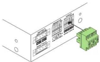
Figure 17
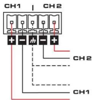
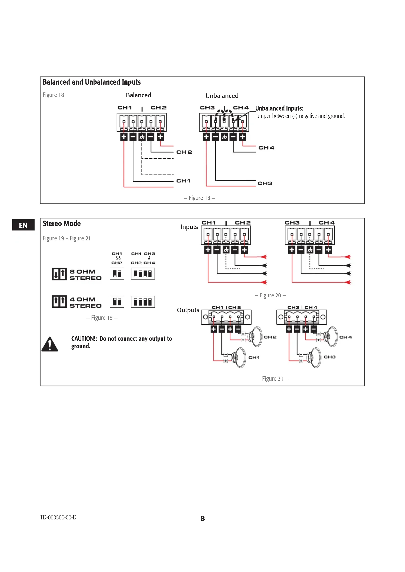
Balanced and Unbalanced Inputs
Figure 18
Balanced
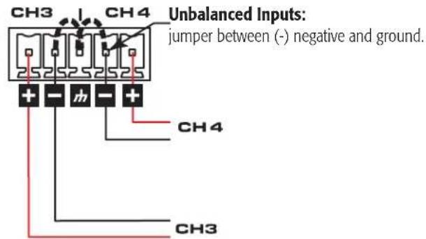
Unbalanced
Figure 18
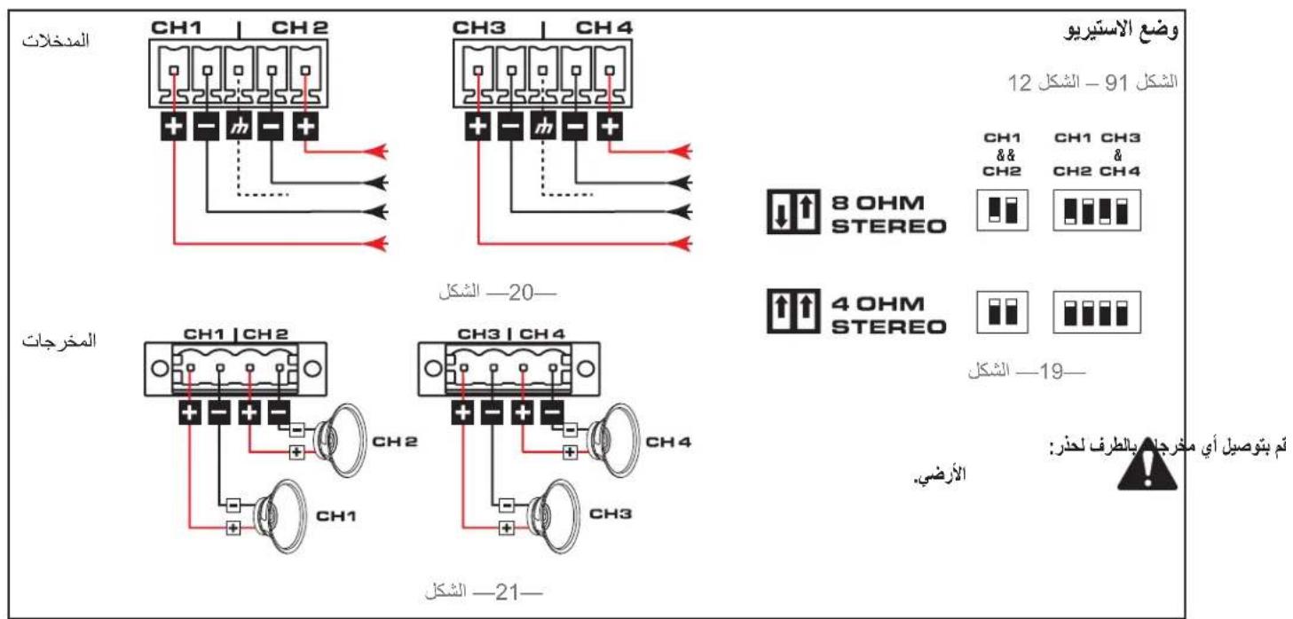
Figure 19
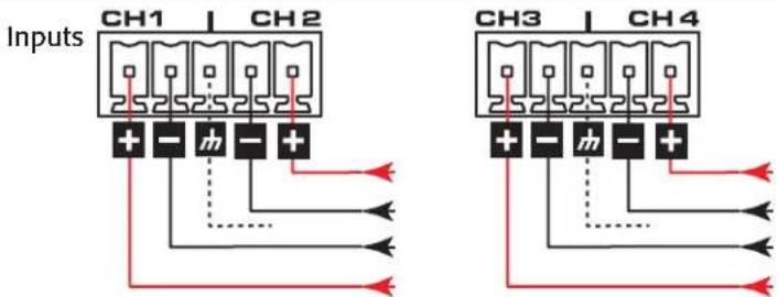
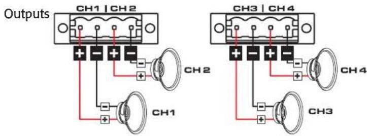
Figure 20
Figure 21
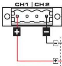
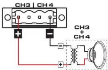
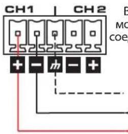
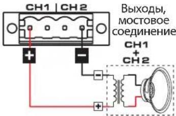
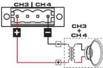
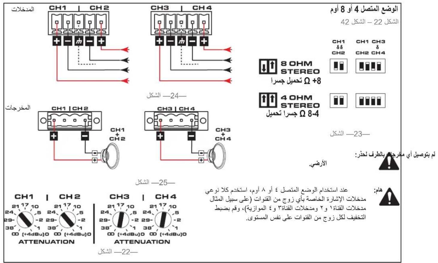
4 or 8-ohm Bridged Mode
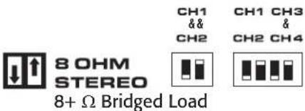
Figure 22 - Figure 25
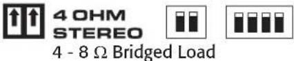
Figure 22
Inputs
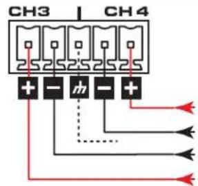

Figure 23
Outputs
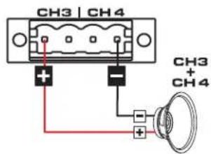
Figure 24

CAUTION!: Do not connect any output to ground.

IMPORTANT: When using 4 or 8-ohm Bridged Mode, use both signal inputs of a channel pair (for example parallel CH1&2 inputs and parallel CH3&4 inputs), and set the attenuation for each channel pair to the same level.
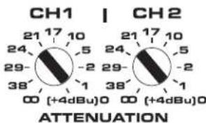
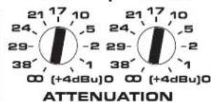
Figure 25
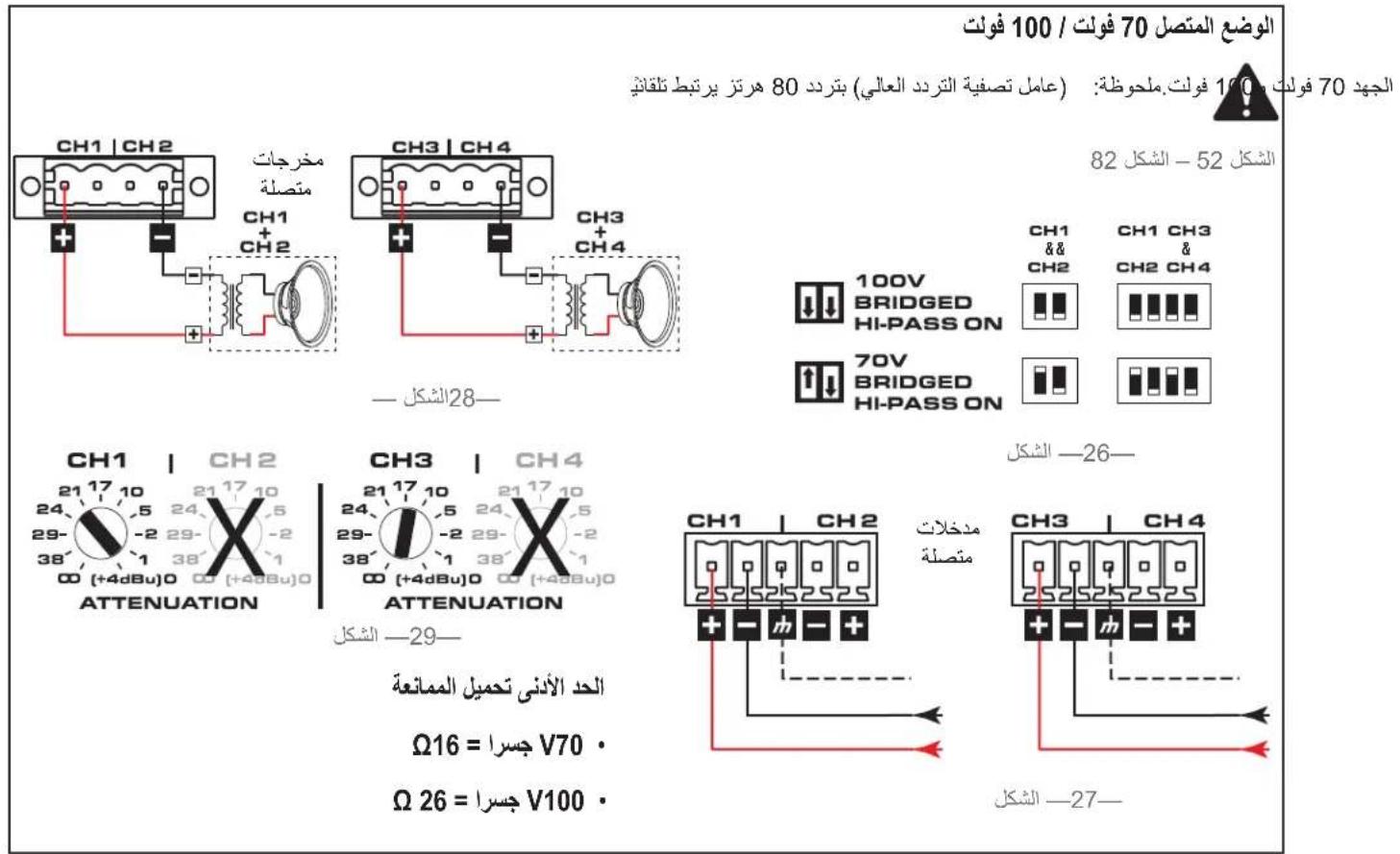
70V/100V Bridge Mode

NOTE: 80Hz (high-pass filter) is auto-engaged in bridged 70 V and 100 V modes
Figure 26 - Figure 29

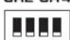
100V BRIDGED HI-PASS ON

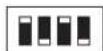
70V BRIDGED HI-PASS ON
CH1 CH3 & CH2 CH4

CH1 CH3 & CH2 CH4
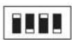
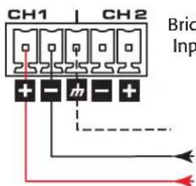
Figure 26
Bridged Inputs
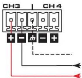
Figure 27
Bridged Outputs
Figure 28
Minimum Load Impedance:
- 70V Bridged = 16 Ω
100V Bridged = 26
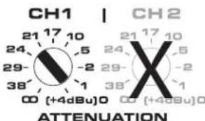
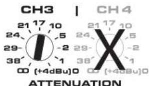
Figure 29
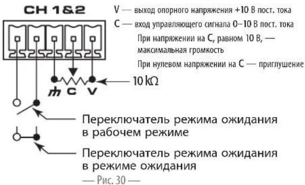
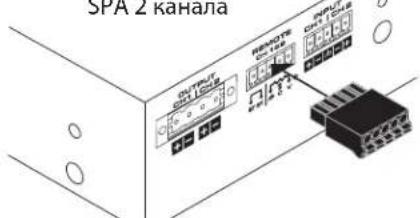
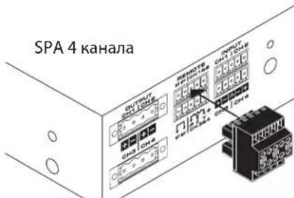
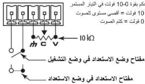
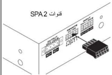
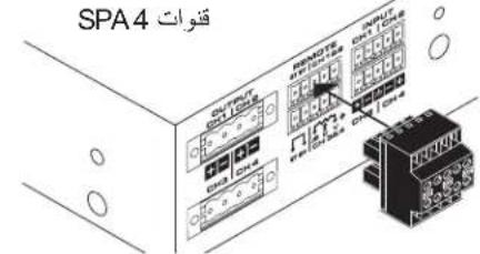
Remote
Figure 30 - Figure 32
SPA 2-channel
(1)
3.5mm, 5-pin
SPA 4-channel
(1)
3.5mm, 10-pin
When the potentiometer is at the minimum position, the amplifier goes into Mute mode. On the SPA 4-channel amplifier, the remote level controls for channel 1 & 2 are independent from channels 3 & 4 remote level control.
On the SPA 4-channel model, closing the "Standby Switch" between the first two pins of either Ch1-Ch2 or Ch3-Ch4 causes all four channels to go into Standby.
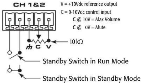
Figure 30
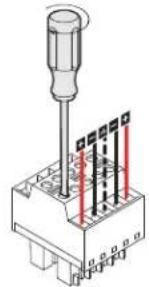
Figure 31
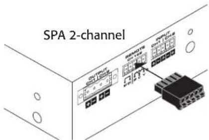
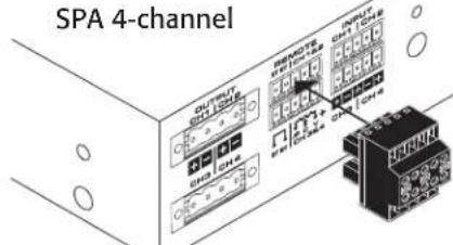
Figure 32
Specifications
| SPA2-60 2 Channels | SPA4-60 4 Channels | SPA2-200 2 Channels | SPA4-100 4 Channels | |
| Stereo Mode (all channels driven) | ||||
| 8 Ω 60 W 60 W 200 W 100 W | ||||
| 4 Ω 60 W 60 W 200 W 100 W | ||||
| Bridged Outputs (per bridged output pair) | ||||
| 8 Ω and 4 Ω 200 W 200 W 400 W 200 W | ||||
| 70 V 250 W 250 W | i | 350 W 350 W | i | |
| 100 V 250 W 250 W | i | 350 W 350 W | i | |
| Frequency Response (4 Ω and 8 Ω) 20 Hz - 20 kHz +/- 0.1 dB | ||||
| Signal to Noise (20 Hz - 20 kHz) >100 dB | ||||
| Input Sensitivity 1.23 V (+4 dBu) | ||||
| Gain at 8 Ω 25 dB 25 dB 30 dB 27 dB | ||||
| Output Circuitry Class D | ||||
| Input Impedance >10k, balanced or unbalanced | ||||
| Maximum Input Level 12.3 V (+24 dBu) | ||||
| Cooling | Convection | |||
| Input Connectors | ||||
| SPA 2-channel | 3.5 mm Euro, 5 pin (green) | |||
| SPA 4-channel | 3.5 mm Euro, 10 pin (green) | |||
| Remote Connectors | ||||
| SPA 2-channel | 3.5 mm Euro, 5 pin (black) | |||
| SPA 4-channel | 3.5 mm Euro, 10 pin (black) | |||
| Output Connectors | ||||
| SPA 2-channel | One 5 mm Euro, 4 pin (green) | |||
| SPA 4-channel | Two 5 mm Euro, 4 pin (green) | |||
| Front Panel Indicators Power, Signal (per channel), Limit/Mute/Protect (per channel) | ||||
| Rear Panel Indicators | Two-colored LED Signal/Limit/Mute/Protect (per channel) | |||
| User-configurable Operating Modes (4-channel or equivalent operating mode can be independently configured per channel pair) | Low Impedance 4 Ω and 8 Ω operation, or High-impedance bridged direct drive of 70V & 100V distributed audio systems | |||
| General Purpose Inputs (GPI) | Remote Volume, Remote Standby, on 3.5 mm connectors (10k potentiometer is not included) | |||
| Highpass Filter | 80 Hz auto-engaged in Bridged 70 V & 100 V modes | |||
| Dimensions 1.7" x 8.7" x 9.5" (43 mm x 220 mm x 241 mm) | ||||
| Net Weight | 3.5 lb (1.6 kg) | 4.0 lb (1.8 kg) | 3.5 lb (1.6 kg) | 4.0 lb (1.8 kg) |
| Shipping Weight | 6 lb (2.7 kg) | 6.5 lb (3.0 kg) | 6 lb (2.7 kg) | 6.5 lb (3.0 kg) |
| Power Requirements | Universal Power Supply (with active power factor correction), 100 - 240 VAC, 50 - 60 Hz | |||
| Agency Approvals | UL, CE, Energy Star, RoHS/WEEE compliant, FCC Class B (Conducted and Radiated emissions), UL 2043 with PL-KIT | |||
| Carton Contents | IEC Cable, Installation Guide, Connector Pack, Rack Mount Ears, Mounting Brackets | |||
1 Peak Power - dependent on channel loading
QSC
Mailing Address:
QSC, LLC
1675 MacArthur Boulevard
Costa Mesa, CA 92626-1468 USA
Telephone Numbers:
Main Number: (714) 754-6175
Sales & Marketing: (714) 957-7100 or toll free (USA only) (800) 854-4079
Customer Service: (714) 957-7150 or toll free (USA only) (800) 772-2834
Facsimile Numbers:
Sales & Marketing FAX: (714) 754-6174
Customer Service FAX: (714) 754-6173
World Wide Web:
www.qsc.com
E-mail:
info@qsc.com
service@qsc.com
System Power Amplifier (SPA)
Guía de instalación

Figure 12 - Figure 13
IMPORTANT! Câblage classe 2
SPA 2-canaux
(1)
SPA 4-canaux
(2)
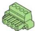
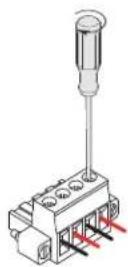
Figure 12
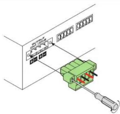
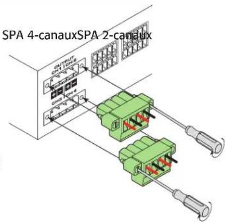
Figure 13
Figure 14 - Figure 15
(1)
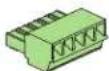
Figure 16 - Figure 17
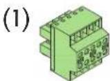
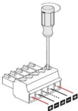
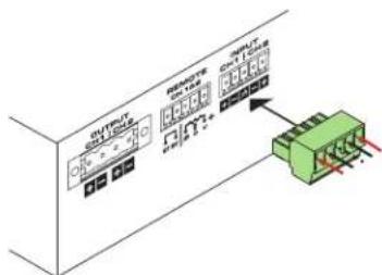
Figure 14
Figure 15
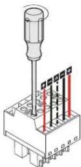
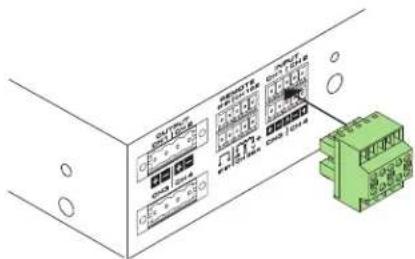
Figure 16
Figure 17
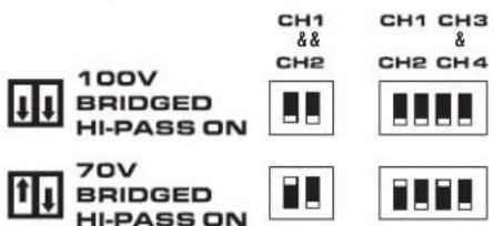
Figure 26 - Figure 29
Figure 30 - Figure 32
SPA 2-canaux
(1)
3,5 mm, 5 broches
SPA 4-canaux
(1)
3,5 mm, 10 broches
100V BRIDGED HI-PASS ON
CH1
&&CH2
CH1 CH3
& CH2 CH4

70V BRIDGED HI-PASS ON

Bb6op konhpyaun npu yctahOBke ycuiNTeJia
Bb6epate OIMN I3 npdeJIOXeHHbIX HxKc BapnHToB KOHmrypaAM.
A. OJHH yCNIHTeB 19-IOIIMOBO B CTIOKE (DINY yCTaHOBKN CIEBA NIN CNIPABA) cTpaHnue 63
D. PaaMeIeHHe NIO paobouHM CTOLOM HnHa cTeHe cTaPAnHc64
B.ДыусителВ19-ДИМOBОIстIKE(CБИСТУПОЕнаружNepeHENnN 3aDHeN nAhenbO) cTpaHnue 63
E.Cbo6oHoe paMaeeHHe Ha paoeem cToJe nnDpyoN noBepxHoCTn CTpaHue 65
C.норненгдяуctановкndnoHOrOусnteTЯ B noNOBHy croK (cBbCtynakueHapyKy nepeHHe mnn 3aHHe naneHbO) ctpnHaIe 64
E.YCTAHOBKA BUCCTemyBEHTNIAUINCTPAHINCE65
INPMUEAHHE:80T(ΦnNbTpBbICOKNX aACTOT)ABOTMaTHUeCKN BKNIOuHaETCJIA MOCTOBbIX coeUNHeHNI70BN100B
Pnc.25 Pnc.28

100V BRIDGED HI-PASS ON

70V BRIDGED HI-PASS ON
CH1


CH1 CH3
&
Pnc.26
XObl, CTOBOE DHeHHe

Pnc.28
Pnc.29
MHHMaJIbHoe cOnpoTHBHeHne HArpy3Kn:
- 70B MOCTOBOB BbIXoD = 16 OM
100BMOCTOBONBIXO=26OM
Pnc.27
ДиctaHIOHOHoe KOHTpOnlb
ypOBHrPOMKoCTM
Pnc.29-Pnc.31
SPA 2 KaHaJa
(1)
3,5 MM, 5-TH UTBIPbKOBbbpa3bem
SPA 4 KaHana
(1)
3,5 MM, 10 TM TLbPbKOBBi
Korda notehuHOMeTp haoDITcB NonoKeHH, COOTBETCTBYKUEM MHHMmAbHMOy CNHany, yCNHTeIb nepexoDIT B pekm npnHyWeHH. 3NeMeHTb DnCTAHNOHHO ynpaBHeHHa dn KaHanob 1 n 2 Ha ycHNTe SPA 4 KaHana paOtaKo He3aBNCMO O TneMeHTOB ynpaBHeHHa dn KaHanob 3 n 4.
BMOJIN SPA 4 KaHana 3aMbKaHne nepeKIOUaTeIe peKIMoXnDaHmMeXyDn PEPbIMn DByMn KOHTaKtMaHa KaHaNax 1 n 2 mnn 3 n 4 npmbouT K nepeKDOy B pexkIM OxNDAHm BcEx qETbIPex KaHAnOB.
SPA2KaHana
SPA 4 kaHaJa
PWC.32
TexHnueckne xapaKTepeNtNK
| SPA2-60 2 kanana | SPA4-60 4 kanana | SPA2-200 2 kanana | SPA4-100 4 kanana | |
| Рек�� Стесо (празрабоча лесхkanалов) | ||||
| 8 Oм | 60 Bt | 60 Bt | 200 Bt | 100 Bt |
| 4 Oм | 60 Bt | 60 Bt | 200 Bt | 100 Bt |
| Мостове седимене вухобов (пая калдую пapy вухобов с мостовik coedimenuнem) | ||||
| 8 и 4 Oм | 200 Bt | 200 Bt | 400 Bt | 200 Bt |
| 70 B | 250 Bt | 250 Bt' | 350 Bt 350 Bt | ' |
| 100 B | 250 Bt | 250 Bt' | 350 Bt 350 Bt | ' |
| ЧадOTТУСЕАКТERTСКА (4 Oм и 8 Oм) | 0t 20 du do 20 kTu +/ - 0,1 du | |||
| Ол���име «СкногAL/шьг» (ot 20 Tú до 20 kTu) | Балус 100 du | |||
| «Чавелейные в�ыд» | 1,23 B (+4 du otioстень урobио 0,775 B) | |||
| Уckлины (m 25,0 du | ||||
| КлASS Вухлары (evel KlASS D | ||||
| Иmsmedic baxoda | Балуse 10 KOM, δаланский (a Ha Hb Hb Hb Hb Hb Hb Hb Hb Hb Hb Hb Hb Hb Hb Hb Hb Hb Hb Hb Hb Hb Hb Hb Hb Hb Ha Hb Hb Hb Hb Hb Hb Hb Hb Hb Hb Hb Hb Hb Hb Hb Hb Hb Hb Hb Hb Hb Hb Hb Ha Ha Hb Hb Hb Hb Hb Hb Hb Hb Hb Hb Hb Hb Hb Hb Hb Hb Hb Hb Hb Hb Hb Hb Hb HB | 12,3 B (+24 du otioстень урobио 0,775 B) | ||
| Олжандуve | ||||
| Вухотны (aPblM) | Балузв (3,5 MM, 5-шырков (uBchu Bh uBhu Bh uBhu Bh uBhu Bh uBhu Bh uBhu Bh uBhu Bh uBhu Bh uBhu Bh uAHu Bh uBhu Bh uBhu Bh uBhu Bh uBhu Bh uBhu Bh uBhu Bh uBhu Bh uBhu CH uBhu Bh uBhu Bh uBhu Bh uBhu Bh uBhu Bh uBhu Bh uBhu Bh uBhu Bh aH aH aH aH aH aH aH aH aH aH aH aH aH aH aH aH aH aH aH aH aH aH aH aH aH a H aH aH aH aH aH aH aH aH aH aH aH aH aH aH aH aH aH aH aH aH aH aH aH aH aG | 12,3 B (+24 du otio stень урobио 0,775 B) | ||
| Вухотны (aPblM) | Балузв (3,5 MM, 5-шырков (uBchu Bh uBhu Bh uBhu Bh uBhu Bh uBhu Bh aH aH aH aH aH aH aH aH aH aH aH bH bH bH bH bH bH bH bH bH bH bH bH bH bH bH bH bH bH bH bH bH bH aH aH aH aH aH aH aH aH aH aH aH aH aH aH aH aH aH aH aH aH aH aH aH aH bH bH bH bH bH bH bH bH bH bH bH bH bH bB | 12,3 B (+24 du otio stень урobио 0,775 B) | ||
| Вухотны (aPblM) | Балузв (3,5 MM, 5-шырков (uBchu Bh uBhu Bh uBhu B\h uBhu Bh uBhu Bh uBhu Bh uBhu Bh uBhu Bh uBhu Bh uBhu Bh uBhu Bh uBhuBh uBhuBh uBhuBh uBhuBh uBhuBh uBhuBh uBhuBh uBhuBh uBhuBhuBhuBhuBhuBhuBhuBhuBhuBhuBhuBhuBhuBhuBhuBhuBhu$B A | 12,3 B (+24 du otio stень урobио 0,775 B) | ||
| Вухотны (aPblM) | Балузв (3,5 MM, 5-шырков (uBchu Bh uBhu Bh uBhu $B B | 12,3 B (+24 du otio stень урobио 0,775 B) | ||
| Вухотны (aPblM) | Балузв (3,5 MM, 5-шырков (uBchu $B B | 12,3 B (+24 du otio stень урobио 0,775 B) | ||
| Вухотны (aPblM) | Балузв (3,5 MM, 5-шырков (uBchu B | 12,3 B (+24 du otio stень урobио 0,775 B) | ||
| Вухотны (aPblM) | Балузв (3,5 MM, 5-шырков ($u B | 12,3 B (+24 du otio stень ур B | 12,3 B (+24 du otio st<|im_start|> | 12,3 B (+24 du otio st<|im_start|> |
| Вухотны (aPblM) | Балузв (3,5 MM, 5-шырков ($u B | 12,3 B (+24 du otio st<|im_start|> | 12,3 B (+24 du otio st<|im_start|> | |
| Вухотны (aPblM) | Балузв (3,5 MM, 5-шырков ($u B | 12,3 B (+24 du otio st<|im_start|> | 12,3 B (+24 du otio st<|im_start|> | |
| Вухотны (aPblM) | Балузв (3,5 MM, 5-шырков ($u B | 12,3 B (+24 du otio st<|im_start|> | 12,3 B (+24 du otio st<|im_start|> | |
| Вухотны (aPblM) | Балузв (3,5 MM, 5-шырков ($u B | 12,3 B (+24 du otio st<|im_start|> | 1.8 Kt (4,0 lb) | |
| Вухотны (aPblM) | Балузв (3,5 MM, 5-шырков ($u B | 12,3 B (+24 du otio st<|im_start|> | 1.8 Kt (4,0 lb) | |
| Вухотны (aPblM) | Балузв (3,5 MM, a 5-шырков ($u B | 12,3 B (+24 du otio st<|im_start|> | 1.8 Kt (4,0 lb) | |
| Вухотны (aPblM) | Балузв (3,5 MM, a 5-шырков ($u B | 12,3 B (+24 du otio st<|im_start|> | 1.9 Kt (4,0 lb) | |
| Вухотны (aPblM) | Балузв (3,5 MM, a 5-шырков ($u B | 12,3 B (+24 du otio st<|im_start|> | 1.9 Kt (4,0 lb) | |
| Вухотны (aPblM) | Балоузв (3,5 MM, a 5-шырков ($u B | 12,3 B (+24 du otio st<|im_start|> | 1.9 Kt (4,0 lb) | |
| Вухотны (aPblM) | Балузв (3,5 MM, a 5-шырков ($u B | 12,3 B (-24 du otio st<|im_start|> | 1.9 Kt (4,0 lb) | |
| Вухотны (aPblM) | Балузв (3,5 MM, a 5-шырков ($u B | 12,3 B (-24 du otio st<|im_start|> | 1.9 Kt (4,0 lb) | |
| Вухотны (a #Pbl M) | Балузв ($3,5 MM, a 5-шырков ($u B | 12,3 B (-24 du otio st<|im_start|> | 1.9 Kt (4,0 lb) | |
| Вухотны (a #Pbl M) | Балузв ($3,5 MM, a 5-шырков (u | 12,3 B (-24 du otio st<|im_start|> | 1.9 Kt (4,0 lb) | |
| Вухотны (a #PblM) | Балузв (3,5 MM, a 5-шырков ($u B | 12,3 B (-24 du otio st<|im_start|> | 1.9 Kt (4,0 lb) | |
CopepMAOye naKOBn
Kabenb nanaHn IEC,pykoBcTNO no 6ctpoW cTApTy,Haob npaaeMoB,ckoBn KpOHeuBn Dn TaKpennnBn B CTae
1 NIKOBaMoUHOCb-3aBNCNTOTHaRpy3KaHaHaJa
QSC
PouTOBbIaApec
KoMaHaHa QSc, LLC
1675 MacArthur Boulevard
Costa Mesa, CA, 92626-1468, CUSA
TenefoHbI
OchOBHOHOMeP: (714) 754-61-75
PioaJnHmApKeTnHr:714)957-71-00 Hn6ecnTaHbHmHOmep(ToIbkoDnC)(800)854-40-79
Cnykba KInmTeTckoi nOndepKKn: (714) 957-71-00 mnn bocnntbHIO HOMeP (ToIbKO dna CIIA) (800) 772-40-79
Homepa akcoB
Фанс OTДела Маркетинги и рождх: (714) 754-61-74
Qakcnykbsklnnentckoi npndepkkn: (714) 754-61-73
Aqpcc B HInTePheTc
www.qsc.com
ZIeKTPoHHaH 10uTa
info@qsc.com
service@qsc.com
QSC
System Power Amplifier (SPA)
山
2 SPA
4 SPA
jg 2
j 1
a 1
J 1
Aegell aieyI ciey (aia) "NOTE" eaei
i 1
a a a a a a a a a a a a a a a a a a a a a a a a a a


a
| (2x) QSC P/N CH-001345-00 | (2x) QSC P/N CH-001344-00 | (1x) QSC P/N CH-001344-00 | (1x) QSC P/N CH-001344-00 | (1x) QSC P/N CH-001344-00 | (1x) QSC P/N CH-001344-00 |
| (4x) QSC P/N PL-001023-00 | (6x) QSC P/N PL-001023-00 | (6x) QSC P/N PL-001023-00 | (6x) QSC P/N PL-001023-00 | (6x) QSC P/N PL-001023-00 | (6x) QSC P/N PL-001023 |
| (1x) 2x2SPA QSC P/N CO-000645-00 | (1x) 2x2SPA QSC P/N CO-000645-00 | (1x) 2x2SPA QSC P/N CO-000645-00 | (1x) 2x2SPA QSC P/N CO-000645-00 | (1x) 2x2SPA QSC P/P CO-000645-00 | (1x) 2x2SPA QSC P/P CO-000645-00 |
| (1x) QSC P/N TD-000337 | (1x) QSC P/N TD-000337 | (1x) 2x2SPA QSC P/N TD-000337 | (1x) 2x2SPA QSC P/N TD-000337 | (1x) 2x2SPA QSC P/N TD-000337 | (1x) 2x2SPA QSC P/N TD-000337 |
1-1
A. 96 ÷ 11
6 6
Sn = na1 + ( n - 1) 2
C. g all

QSCn pabll Cg Ss
Cleblal jnaa aall qall naiy: Ie yaaia
Gall pala ll aall gall ydi. Jl all lll 1
Sall jaiy glall aell eall aall aall
Sall (jay) jy aall /dall LED 1
Aall jy aall jy aall jy aall Ld A
Ld
y
a a
75 a 19 176
75 a (j 19 1
76 a (j) 10
77
77 a 1
AR
AR
A
aiai
Jal
2 CHANNEL AMPLIFIER SPA2
4 CHANNEL AMPLIFIER SPA4
js . 19
aai 1
10
4,3 10
43 11
1 aiei jia 5
2,1
4,3 12
S木弟形 COBD = S COD + S BDO = S BOC +
2aii jia jia 6
2,1 1
4 sll jg jg jai 14
2,1 jaiiall gaiy
2,1 3
8
41 LED
4,3 2
s# 3 s# -a
1 2
dai jai dai jai
yall yj yjj - j.
aalaae aee
1.
LED 10 sds 1
(1)

-31
CH1&2
30
13 JS-92 JS-
2 SPA
4 SPA
(1)
jui5j 3.5 jy
SPA2
32
sag g aall llaa y laie
gall gao gao gao 4 gao SPA gao gao 21
gai gao gao gao gao gao 23
4,3 gao gao
4 4 SPA jalal
QSC Audio Products, LLC
1675 MacArthur Boulevard
Costa Mesa, CA 926261468 USA
:aell alj
(714) 754-6175:
(714)957-7100:
(800) 854-4079 (aee aee
aill (y) (714) 957-7150 :
(800) 772-2834 (
:ssllj
(714) 7546174:
(714) 7546173:
1ai,1bi,1c_i
www.qsc.com
12
info@qsc.com
service@qsc.com