
SR 120 Set - Screwdriver METABO - Free user manual and instructions
Find the device manual for free SR 120 Set METABO in PDF.
| Product type | Pneumatic impact screwdriver |
| Brand | Metabo |
| Model | SR 120 Set |
| Category | Screwdriver |
| Power supply | Compressed air |
| Maximum operating pressure | 6 bar |
| Air flow rate | 320 l/min |
| No-load speed | 8,000 rpm |
| Square drive | 1/2" |
| Max. screw capacity | M16 |
| Max. torque (right/left rotation) | 320 Nm |
| Impact mechanism | Hammer |
| Dimensions (L × W × H) | 195 × 70 × 195 mm |
| Weight | 2,2 kg |
| Sound power level (LWA) | 105 dB(A) |
| Sound pressure level (LPA) | 94 dB(A) |
| Vibration (weighted RMS value) | 10,4 m/s² |
| Hose inner diameter | 9 mm |
| Air connection | 1/4" |
| Delivery contents | 1 impact screwdriver SR 120, 1 R 1/4" adapter, 10 socket wrenches (9, 10, 11, 13, 14, 17, 19, 22, 24, 27 mm), 1 extension, 1 plastic case, operating instructions |
| Recommended accessories | Pneumatic oil 0,5 L (ref. 090 100 8540), lubricator R 3/8" (ref. 090 105 4592) |
| Maintenance | Regular lubrication with pneumatic oil every 15 minutes of continuous use; 3 to 5 drops in the air connection |
| Safety | Wear safety glasses and hearing protection; do not exceed 6 bar; disconnect air supply before maintenance |
| Repairs | Entrust exclusively to qualified personnel; contact Metabo customer service |
Frequently Asked Questions - SR 120 Set METABO
User questions about SR 120 Set METABO
0 question about this device. Answer the ones you know or ask your own.
Ask a new question about this device
Download the instructions for your Screwdriver in PDF format for free! Find your manual SR 120 Set - METABO and take your electronic device back in hand. On this page are published all the documents necessary for the use of your device. SR 120 Set by METABO.
USER MANUAL SR 120 Set METABO
We herewith declare in our sole responsibility that this product complies with the following standards in accordance with the regulations of the undermentioned Directives*
Director Innovation, Research and Development
Dokumentationsbevollmachtigter/ responsible person for documentation/ Chargé de la documentation
Metabowerke GmbH
Metabo-Allee 1
D-72622Nurtingen

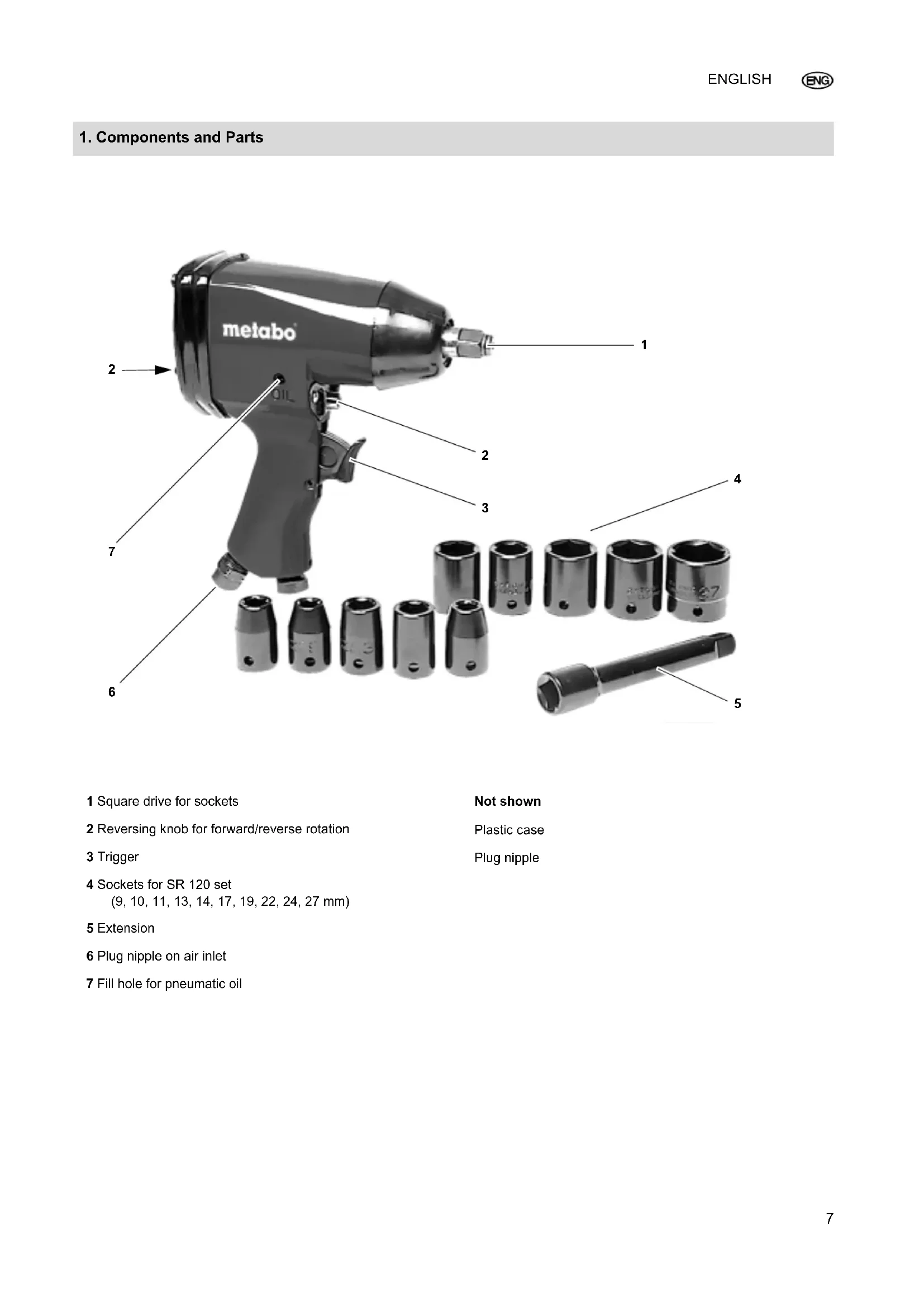
1. Components and Parts
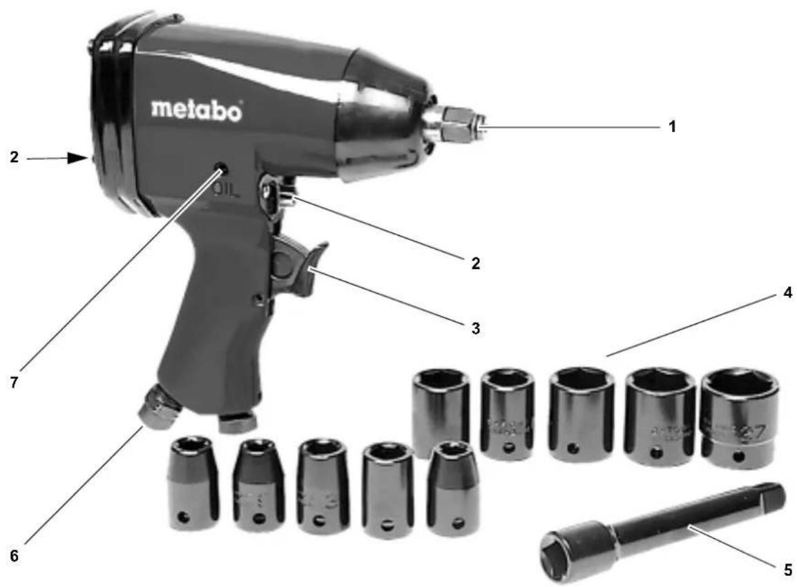
1 Square drive for sockets
2 Reversing knob for forward/reverse rotation
3 Trigger
4 Sockets for SR 120 set
(9, 10, 11, 13, 14, 17, 19, 22, 24, 27 mm)
5 Extension
6 Plug nipple on air inlet
7 Fill hole for pneumatic oil
Not shown
Plastic case
Plug nipple
Table of Contents
- Components and Parts
- Please Read First!
- Safety
- Operation
- Care and Maintenance
- Repairs
- Protection of the Environment
- Scope of delivery
- Accessories
- Technical specifications
2. Please Read First!
These operating instructions have been written for you, the user, to learn how to operate this device and to do so safely. These instructions should be used as follows:
- Read these instructions in full before operating. Pay special attention to the safety instructions.
- These operating instructions are intended for people with basic technical knowledge regarding the operation of a tool like this. If you have no experience with this type of tool you are strongly advised to seek competent advice and guidance from an experienced person before operating this tool.
- If you notice transport damage while unpacking, notify your supplier immediately. Do not operate the tool!
- Dispose of the packing in an environmentally friendly manner. Take to a proper collection point.
- Keep all documents supplied with the tool for future reference. Retain your proof of purchase in case of a future warranty claim.
- If you hire out or sell this tool be sure to hand over the tool documents supplied.
- The equipment manufacturer is not liable for any damage arising from disregard of these instructions.
The information in these instructions is designated as below:

Danger!
Risk of personal injury or environmental damage.

Risk of electric shock!
Risk of personal injury by electric shock.

Caution!
Risk of material damage.

Note:
Supplementary information
- At times numbers are used in illustrations (1, 2, 3, ...). These numbers:
- indicate component parts;
- are consecutively numbered; and
- correspond with the number(s) in brackets (1), (2), (3) ... in the neighbouring text.
- Numbered steps must be carried out in sequence.
- Instructions which can be carried out in any order are indicated by bullet points () .
- List items are indicated by dashes (-).
3. Safety
3.1 Specified Conditions of Use
This tool is suitable for DIY fastening and removing of hexagon nuts and bolts.
This tool may only be powered by a compressed air supply. The max. permissible working pressure stated in the Technical Specifications must not be exceeded. This tool must not be operated with gases that are explosive, combustible or detrimental to health.
Any other use is not as specified. Use not as specified, modification of the tool or use of parts not approved by the manufacturer can cause unforeseeable damage!
3.2 General Safety Instructions
When using this air tool follow the safety instructions given below, to exclude the risk of personal injury or material damage.
Please also observe the special safety instructions in the respective chapters.
Observe the statutory accident insurance institution regulations and regulations for the prevention of accidents pertaining to the operation of air compressors and air tools, where applicable.

General hazards!
- Keep your work area tidy - a messy work area invites accidents.
- Be alert. Do not operate this tool while under the influence of drugs, alcohol or medication.
- Keep air tools out of the reach of children.
- Connect this tool to the compressed air supply by means of a quick coupling only.
- Make sure that the max. permissible working pressure stated in the Technical Specifications is not exceeded.
- Do not overload tool - use it only within the performance range it was designed for (see Technical Specifications).
- Keep the tool from jamming - ensure firm footing when using the tool.
- Do not touch any rotating parts.
- Disconnect from air supply before
- changing sockets,
- eliminating faults.
- when tool is left unattended.
Hazard generated by insufficient personal protective equipment!
Wear hearing protection.
Wear safety goggles.
Hazard generated by tool defects!
Take good care of the tool. Observe the maintenance instructions.
- Do not attempt to repair the tool yourself! Only trained specialists are permitted to service or repair compressors, pressure vessels and air tools.

Protect the tool, air inlet, drive square, and operating elements in particular, from dust and dirt.
- Let tool run idle for a short time only.
3.3 Symbols on the machine

8

9

1

0
8 PI ease read the manual before using the tool.
9 Wear eye protection.
10 Wear ear protection.
11 CE symbol
4. Operation
4.1 Prior to initial operation
Install the plug nipple.
4.2 Using the Tool

The compressed air line must be free of condensed water.

To ensure a long service life of this tool, it needs to be supplied with sufficient quantities of pneumatic oil. This can be achieved by:
- To obtain oil-containing compressed air attach an oiler or in-line oiler or
- manually pour about 3 to 5 drops of pneumatic oil per 15 minutes of operation (continuous operation) into the compressed air port or the fill hole for pneumatic oil.
If the tool has not been used for a period of at least several days manually pour about 5 to 10 drops of pneumatic oil into the compressed air port or the fill hole for pneumatic oil.
- Put socket on the square drive.
-
Set direction of rotation with the reversing knob:
-
Forward: Position changeover switch in direction 'F' and depress button.
-
Reverse: Position changeover switch in direction 'R' and depress button.
-
Set the operating pressure on the compressor (see 'Technical data' for maximum allowable working pressure).
- Connect quick coupler to the air supply.
- Pull trigger to start.
5. Care and Maintenance

Always disconnect from air supply before servicing.
Maintenance and repair work not described in this chapter must be carried out by qualified specialists only.
- Check all screwed connections for tightness and tighten if necessary.
- Do not store tool unprotected outdoors or in humid environment.
6. Repairs

Repairs to air tools must only be carried out by qualified specialists!
Air tools in need of repair can be send to the service centre in your country. Refer to spare parts list for address.
Please attach a description of the fault to the air tool.
7. Protection of the Environment
All packaging materials are recyclable.
End-of-life tools and accessories contain large amounts of valuable raw materials and plastics which must be recycled.
This manual was printed on chlorine-free bleached paper.
8. Scope of delivery
1 impact driver SR 120
1 male coupling, R 1/4"
10 sockets (9, 10, 11, 13, 14, 17, 19, 22, 24, 27 mm)
1 extension
1 Plastic case
1 Operating Instructions
9. Accessories
Pneumatic oil, 0.5 l, art.no.: 090 100 8540
Attachment oiler, R 3/8", art no.: 090 105 4592
10. Technical Specifications
| Air consumption l/min 320 | ||
| Max. permissible working pressure bar 6 | ||
| No-load speed min | -1 | 8,000 |
| Square drive " 1/2 | ||
| Maximum bolt size M16 | ||
| Impact mechanism hammer impact mechanism | ||
| Maximum torque (forward) Nm 320 | ||
| Maximum torque (reverse) Nm 320 | ||
| Hose diameter (inside) | mm | 9 |
| Connector thread " 1/4 | ||
| Vibration (effective value of weighted acceleration) | m/s2 | 10.4 |
| EN ISO 15744 sound power level \( L_{WA}^{*} \)sound pressure level \( L_{PA}^{*} \) | dB (A) dB (A) | 10594 |
| Dimensions: length × width × height | mm | 195 × 70 × 195 |
| Weight | kg | 2.2 |
| * The values stated are emission values and as such do not necessarily constitute values which are safe for the workplace. Although there is a correlation between emission levels and environmental impact levels, whether further precautions are necessary cannot be derived from this. Factors influencing the actually present environmental impact level in the workplace include the characteristics of the work area and other noise sources, i.e. the number of machines and other neighbouring work processes. The permitted workplace values can likewise vary from country to country. This information is intended to assist the user in his estimate of hazards and risks. | ||
10 steeksleutels (9, 10, 11, 13, 14, 17, 19, 22, 24, 27 mm)
1 verlengstuk
(9, 10, 11, 13, 14, 17, 19, 22, 24, 27 mm)
5 Forlaengerstang
6 Holder til nippel (tryklufttilsutninq)
7 Pafyldningsabning til pneumatikolie
Ikke vist
Plastkuffert
Nippel
Indholdsfortegnelse
4 Hylsnycklar for SR 120 set
(9, 10, 11, 13, 14, 17, 19, 22, 24, 27 mm)
5 Förängning
6 Upptagning for sticknippel (tryckluftsanslutting)
7 Pafyllnadsoppning for pneumatikolja
1 Slagskruvare SR 120
1 Hylsa R 1/4"
10 Hylsnycklar (9, 10, 11, 13, 14, 17, 19, 22, 24, 27 mm)
1 Verlängning
1 Plastvaska
1 Bruksanvisining
9. Tillbehör
Pneumatikolja 0,5 liter art.-nr.: 090 100 8540
Tillsatsoljare R 3/8"
art.-nr.: 090 105 4592
10. Teknisk data
ΠλactmaccoBbIyEmoDaHvNk
BCTaBHOn HnInneIb
CopepkanHe
1.063op np6opa
2.Почntыв Вачал!
3. Be 3onacnoctb
4.3KcnNyataunr
5. Texo6cnykBaHne uyxoD
6. PemOH
7. 3aunTa Okp ykaOuSe CpeDbI
8.ObemnoCTaBKn
9.Пинадлжноctn
10. Texhueckne xapaKtepcntuK
2. IpooyntaBbHauane!
DahHoe pyKOBOdCTBO no 3Kcnnyatau cin coCTaBneHO nIy 6bICTPOn 6e30nacHOn pa6Otbl c yCtPOcTBOM.3decb Bb HainTe He6oJbwoi nyTeBOUnteNo daHHOMy pyKOBOdCTBy nO 3Kcnnyatau:
IOnHOCTbIO npOHTne pyKOBOcTBO neped BKNHOeHnEM INHCTpyMeHTa. Oco6oe BHNMaHne yJeJIte yKa3aHnAM no 6e3oNaCHOCTn.
-ДанhoepyK OBOCTBO NO 3KcIpyaTaun paCCHTaHO Ha JIODei C6a3OBbIMN TexHueCKIMN 3HaHNyIMN,HeoBXOIMbIMN dIpa6OtBIC INCTpyMeHTaMn,IOo6HbIMN TEM,KOTOpBIE ONNCbIBaOTcB DaHHOM pyKOBOdCTBe.EcIn y Bac OTCyTCTByETOnbIT pa6OtBIC TaKIMN yCTpOINCTBaMN,Bbl DOJKNbI ChaJaI BOCNoJIb3OBaTbCn NOMUbIO ONbITHbIX CNEuJaINCTOB.
-Пи o6hApUxKeHn IOBpeKdEHN BCJeIcTBVe TpaHcNOpTIpObKN HeMeIeHNO COo6uNTe O HNX pOdaBu. He 3KcPnyaTnpyIte yctpoiCTBO!
Ioxanyucta,ytuun3npyute yanaKOBky 3KOJONUHeCKN pIneMJIeMbICNOcO6OM.CdaBaiTe ee B COOTBeTCTByIOUne NyHKtBI pInema.
-Coxpa HnTe BCE DOKMeHtbl, npnI Iarauounec KnHCTpyMeHTy, UTo6bl npn Heo6xOaMIOCTN IMeTb BO3MOXHOCTb NOnyHTb HyKHyIO IH-OpMaucIO. CoXpaHnTe NOKynHOJek DnI ppeoCTabNeHnB rapaHTnHbIX Cnyaax.
- Ec JIN Bbl peWJIN CdaTb B apEnHy JIN npOaTb yCTpoiCTBO, nepeJaBaIte TaKHe BCIO npNJarAOuOyOcR DOKymeHTaUIO.
OTBeTCTBeHHocTb 3a NOBpeKdEHHRA, BO3HnKUne B pe3yIbTaTe HecO6NIODeHnJaHHoro pyKOBOcTBO NO 3KcPnyatauIN, pOn3BOJNTeJIb He HeceT.
CBeDHeHnB DaHHOM pyKOBoCTBE OTMeueHbI CNeDyUOuMM CNMBONaM:
Onachoctb!
PpeynpeKHeNe 6 onacHocT npabMnpoBaHn nn BpeDe nIg OkpykaIO-ue Cpebl.
OnacHocTb ydapa 3JIeKtpn-ueCKIM TOKOM!
Ppeynpeqkne 6 onacno TpaMnpoBaHn np paBoTe c 3neKtpo06OpydoBaanm.
BHHMaHHe!
PpeynpeKHeHne O Bo3MOxHOM MaTe- pnaIbHOM yuepe6.
i yka3aHne:
DononHumeNBHa uHOpMaua.
LcnpbHa pncyHkax (1,2,3,...)
-0603NaHOTOTdIbHbIeYacT;
- pohymepoBaHbI IO npraKy;
OTHOCTCAK COOTBETCTBYIOUIMM UΦpam B CkO6kax (1), (2), (3), ... B TEKCTe pAOM.
-YKa3aHnI NO pa6Ote,ДЯ KOTOpbIX CNeDyET CO6JIIOdaTb ONpeJeHHyIO NocneDoBATEJIbHOCTb, CHa6KeHbI HymepaUnei.
- Yka3aHnno pa6oTe c npOn3BOJb-HOHNOCNEIOBaTeJIbHOCTbIO 0603-HaueHbI TOKAMN.
-nyHK TbCnCKOB 6o3HaueHbI cepTOyKAMN.
3. Be3onachocTb
3.1 Hndnexkauee npimehenne
DAnHbI INHCTpyMeHT npeHa3HaueH dIy 3akpyuBaHHaNIOKpyuBaHHa BnHTOB C WecTINrpaHHo rONOBKOI
UeCTNrpAHHbIXraekIJIINCNOJb3OBAHnB MaCTepcknx.
DaHHbI INHCTpyMeHT pa3peWaeTc8 3a- NyCKaTb TOJIbKO C NOJKNIOUeHHO JINHnE cKaTOrO BO3dyxa. 3anpeuaetc npBbIwAtb npeJeBHO DOnyCTmOe pa6ooy daBJIeHne, yka3aHHoe B TexHNuecknx XapakTePncTnKax. 3anpeuAETc NcNtB3OBaTb INHCTpyMeHT C B3pbIBOONaCHbIM, TOpOChMn IN BpeDHBIMr3amn.
JIIO6oe INHOE npIMeHHeNe IABnIETcH HeHaJNLeKaUHM. HeHaJNLeKaUee npIMeHHeNe, MoINΦNkaUIN HCTpyMeHTa INN NcOJIb3OBAHne YacTeH, He npOBepeHHbIX IN He OJOpBeHHbIX npON3BOIDTeLEM, MOrY TnpBBeCTN K HenpeDcKa3yEmomy yuep6y!
BbHNTb BCTaBHOn HnInneJb.
4.2 Pa6oTa c HhCtpyMeHTom
BHHMaHHe!
B INHEBMATNueeCKO JINHNI He DOJXHO 6bITb KOHDeHCata.
BHHMaHHe!
Дя Дпгьног рабовинсчрмета 3aJIntbdoCTaTOHoeKoINuecTBO INeBMaTHuueckoro Macna.3To MoXHo CdeJaTb cIeDyUOIMM O6pa30m:
-IVcnoIb3 OBaTb IpomacNeHHb CkaTbI BO3dYx PnI NOMOu YCTaHOBKn MacNeHKn IINoMaNtPaJIbHyO MaCneHky.
NNN
-Ye pe3 kaxdbie 15 MInHyT pa60TbI (peXIM HENpepbBHOJ 3KcNlpyatauun)doabnTb BpyHyIO npImepHo 3-5 KaneNb IINBEMaTHueCKOROMacna B INHNO Daayn CxAtoroBO3dyxa INN Yepe3 3aINBHOE OT-BepCTne INA INHEMaTHueCKOROMacna.
EcHCTpymENT He 3KcNluyaTnpoBaIcra HeckonbKO DHei, DoabBt BpyHyIO npMepHO 5-10 Kanelb NHeBMATueCkoR OMacna BInnIO Noaun CxAtorO BO3dyxa nnu Chepe3 HaJIINBHOe OTBepcTne DnI NHeBMATueCkoro Macna.
- BCTaBnTb TopoBBi raeHbI KJIIOU B KBaDpaTHbI 3aKIM.
- YctaHOBnTb nepeKIOUaTeIeM Ha- npaBHeHne BpaUeHn BnpaBO/BJeBO:
-Ⅰрав bI xOД: NOBepHyTb nepeKJIIOUaTeNb no HAnpaBNeHIOCTpeKN F.
-Ne BbI XoI NOBepHyTb NpeKIIouaTeIb No HAnpaBneHIO CTpeIKN R.
- Hacptpontb pa6ooye daBneHne ha KOMnPecccope (MaKcImaIbHO doNpyCTnmoe pa6ooye daBneHne cm."TexHnueckne xapakTepcntKN").
4.ПодсоeДиHINь 6bIcTpOeIcTByIO 山yIO MyΦTy K MaHnCTpaJIN CxKaTOrO BO3dYxa.
5.ДЯВКЛIOUeHnHaXaTbHa CNYCKOBIpbuHr.
5. Texo6cnyxuBaHne uyxoJ
OnachocTb!
Ipeed BbINHHeHem IIO6bIX pa6oT Ha HNCTpyMeHTe OTcoEINHrTb noaCy CKaTOrO BO3dYxa.
Dpyrne pa6oTbI no pemOnTy n TexO6cJnyKuBaHnIO, HeONuCaHHbIe B daHHoI rnaBe, pa3peWaeTcB bInOpNHrTb TOJbKO CneUaJIncTAm.
-Поверяпе pe3ббовь coerce endineHЯ Ha npOuHocTb, пи Heo6xoJIMOCTHn NOtIaHHTe IX.
He xpaHHTb HNCTpyMeHT 6e3aunTbHa OTKpbITOM BO3dYxhe INI BBOBlaXHOcpe.
6. PemOH
OnachocTb!
PemOH THeBMaTnuecKnx NHCtpymeHTOB DOJXHBbI BbINHOHTb TObKO CNEuAJIcTb!
HeicnpaBhIe INHCTpyMeHTb MOKHO npbcIbTaB B cepBnchbI OTeB BaWei cTpaHe. AApEc BbHaJdTe B CnCKe 3aYactei.
PnBbCblke HcTpymeHa npoc6a ONnCatb BO3HkWyo HeNCnPabHOCTb.
7.3aunTaOkpykaIooeI cpebl
YnakoobHybMaTePmaJI NHCtpymeHTaHa 100% npxOdtI BTOpHOno6pa6oTkn.
N3HOeHHbIe HnCTpyMeHTbI n npHa- dNEXKHOCTn COepKaTb 60JIbWoE KOJNUcETBO CEHHbIX NPON3BOJCTBeHHbIX MATEpnaIOB IN NlactMaccbl, KOTOpbl E NOxOaT DnBTOpHOn O6pa6oTK.
DaHHoe pyKOBOCTBO TAKKe HaneuataHo Ha 6eHHe 6yMaRe, He cOpEpa-ueiXnOp.
8. 06bem nocTabkn
1 yadnbl raikoept SR 120
1 BCTABHON HINNEJB R 1/4"
10topoobbixraeunhixknHouei(9,10,
11, 13, 14, 17, 19, 22, 24, 27 MM)
1yDnHHTenb
1ПлacrMaccOBьчeMoDAHnK
1PykoBOCDBO no 3KcnJyatauH
9. PpHaJneKHOCTN
Пневматушею Масно 0,5л, Apt. №:0901008540
MacneHka DnMa MoTaKa R 3/8", ApT. No:090 105 4592
10. Texhnueckne xapaKTepeNCTIKN


- Components and Parts
- Table of Contents
- Please Read First!
- Danger!
- Risk of electric shock!
- Caution!
- Note:
- Safety
- Specified Conditions of Use
- General Safety Instructions
- General hazards!
- Hazard generated by insufficient personal protective equipment!
- Hazard generated by tool defects!
- Symbols on the machine
- Operation
- Prior to initial operation
- Using the Tool
- Care and Maintenance
- Repairs
- Protection of the Environment
- Scope of delivery
- Accessories
- Technical Specifications
- Indholdsfortegnelse
- Tillbehör
- Teknisk data
- CopepkanHe
- IpooyntaBbHauane!
- Onachoctb!
- OnacHocTb ydapa 3JIeKtpn-ueCKIM TOKOM!
- BHHMaHHe!
- i yka3aHne:
- Be3onachocTb
- Hndnexkauee npimehenne
- Pa6oTa c HhCtpyMeHTom
- Texo6cnyxuBaHne uyxoJ
- PemOH
- 7.3aunTaOkpykaIooeI cpebl
- 06bem nocTabkn
- PpHaJneKHOCTN
- Texhnueckne xapaKTepeNCTIKN
Brand : METABO
Model : SR 120 Set
Category : Screwdriver