
DES121028P - Switch D-LINK - Free user manual and instructions
Find the device manual for free DES121028P D-LINK in PDF.
| Product type | Smart Web Switch with PoE |
| Brand | D-Link |
| Model | DES121028P |
| Dimensions (approx.) | 440 x 200 x 44 mm |
| Weight (approx.) | 2.5 kg |
| Power supply | 100-240 V AC, 50/60 Hz |
| Power consumption (max.) | 150 W |
| PoE (Power over Ethernet) | IEEE 802.3af/at, PoE budget 124 W |
| Network ports | 24 RJ-45 10/100 Mbps PoE ports + 4 RJ-45 10/100/1000 Mbps ports |
| Main functions | Web management, SmartConsole, Telnet, SNMP; VLAN, QoS, IGMP snooping, etc. |
| Ventilation | Built-in fans, ensure ventilation space |
| Mounting | Desktop or 19-inch rack mount (brackets included) |
| Security | Default administrator password: "admin" |
| Maintenance and cleaning | Disconnect before cleaning; use a dry cloth, avoid liquids |
| Spare parts and repairability | Contact D-Link support; parts not specified |
| General information | Manufacturer warranty, online support at support.dlink.com |
Frequently Asked Questions - DES121028P D-LINK
User questions about DES121028P D-LINK
0 question about this device. Answer the ones you know or ask your own.
Ask a new question about this device
Download the instructions for your Switch in PDF format for free! Find your manual DES121028P - D-LINK and take your electronic device back in hand. On this page are published all the documents necessary for the use of your device. DES121028P by D-LINK.
USER MANUAL DES121028P D-LINK
Getting Started Guide For D-Link Web Smart Switch
Getting Started Guide
Erste Schritte
Guide de démarrage
Guida introductiva
This guide gives step-by-step instructions for setting up all D-Link Web Smart switches. Please note that the model you have purchased may appear slightly different from those shown in the illustrations.
For more detailed information about your switch, its components, making network connections, and technical specifications, please refer to the User's Guide included with your switch.
Step 1 - Unpacking
Open the shipping carton and carefully unpack its contents. Please consult the packing list located in the User Guide to make sure all items are present and undamaged. If any item is missing or damaged, please contact your local D-Link reseller for replacement.
- One D-Link Web Smart Switch
- Rack mounting bracket
- Power cord
- User's Guide CD with SmartConsole Utility program
- One multilingual Getting Started Guide
Step 2 - Switch Installation
For safe switch installation and operation, it is recommended that you:
Visually inspect the power cord to see that it is secured fully to the AC power connector
Make sure that there is proper heat dissipation and adequate ventilation around the switch
Do not place heavy objects on the switch
Desktop or Shelf Installation
When installing the switch on a desktop or shelf, the rubber feet included with the device must be attached on the bottom at each corner of the device's base. Allow enough ventilation space between the device and the objects around it.
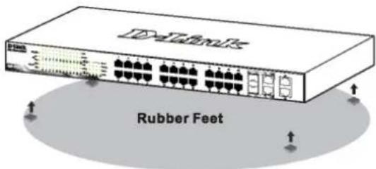
Figure 1. Attaching the rubber feet
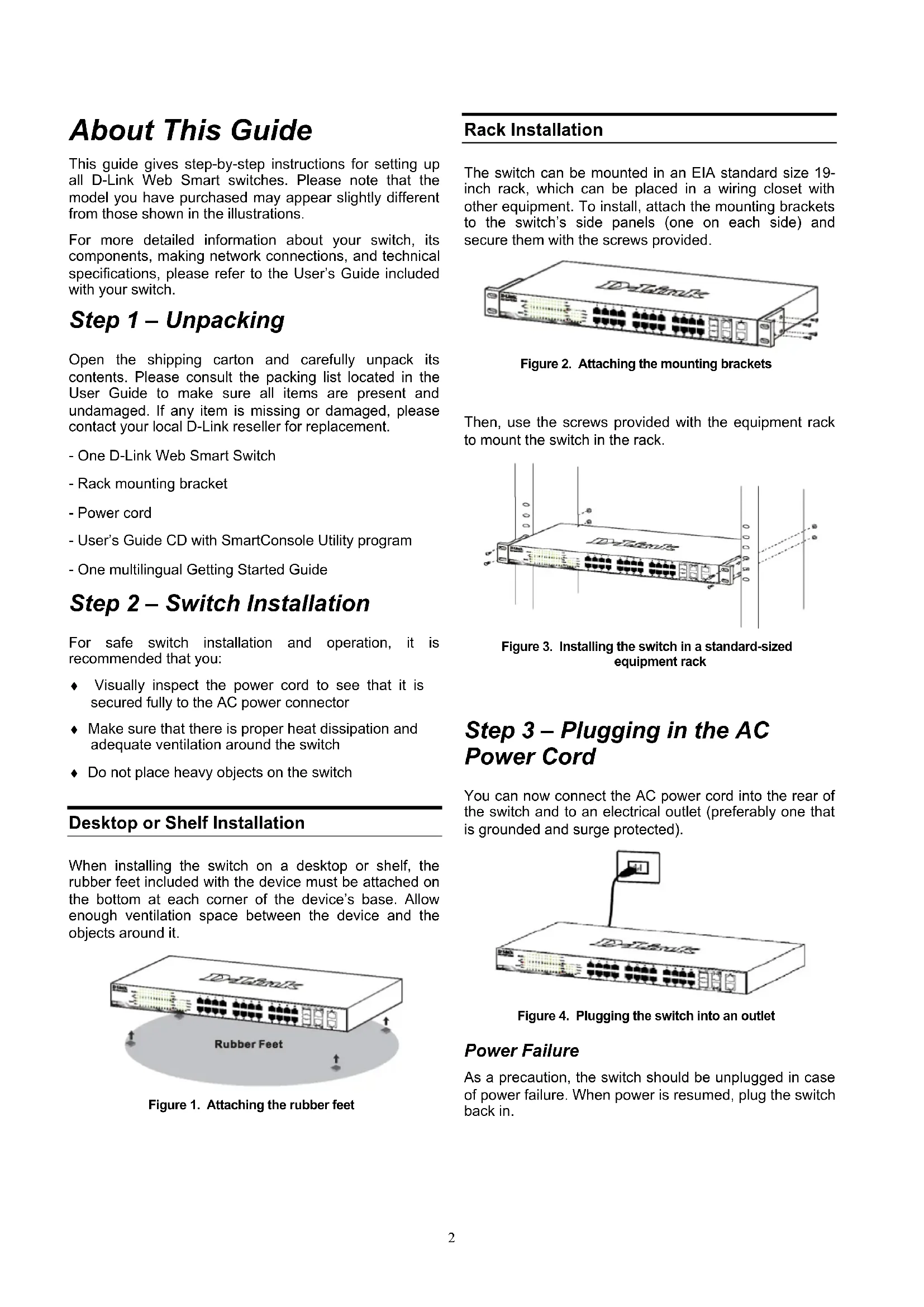
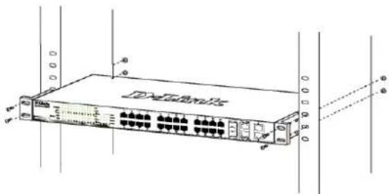
Rack Installation
The switch can be mounted in an EIA standard size 19-inch rack, which can be placed in a wiring closet with other equipment. To install, attach the mounting brackets to the switch's side panels (one on each side) and secure them with the screws provided.
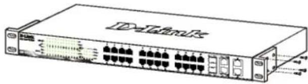
Figure 2. Attaching the mounting brackets
Then, use the screws provided with the equipment rack to mount the switch in the rack.
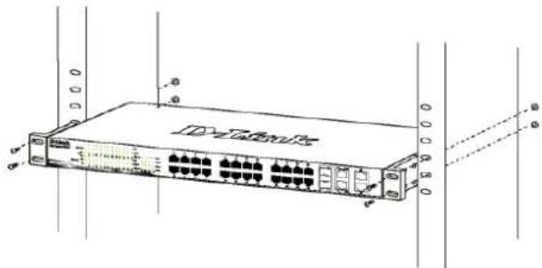
Figure 3. Installing the switch in a standard-sized equipment rack
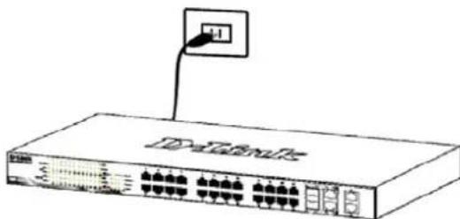
Step 3 - Plugging in the AC Power Cord
You can now connect the AC power cord into the rear of the switch and to an electrical outlet (preferably one that is grounded and surge protected).
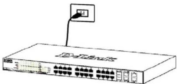
Figure 4. Plugging the switch into an outlet
Power Failure
As a precaution, the switch should be unplugged in case of power failure. When power is resumed, plug the switch back in.
Management Options
The D-Link Web Smart Switch can be managed in-band by using Telnet. The user may also choose the Web-based Management, accessible through a web browser or through any PC using the SmartConsole Utility.
If you want to manage only one D-Link Web Smart Switch, the Web-Based Management is the better option. Each switch must be assigned its own IP Address, which is used for communication with Web-Based Management or an SNMP network manager and the PC should have an IP address in the same range as the switch.
However, if you want to manage multiple D-Link Web Smart Switches, the SmartConsole Utility is the better option. Using the SmartConsole Utility, you don't need to change the IP address of your PC and it is easy to start the initial setting of multiple Smart Switches.
Please refer to the following detailed installation instructions for the Web-Based Management, SmartConsole Utility, Telnet Management and SNMP-Based Management.
Web-based Management Interface
After a successful physical installation, you can configure the switch, monitor the LED panel, and display statistics graphically using a web browser, such as Netscape Navigator (version 6.2 and higher) or Microsoft Internet Explorer (version 5.0 and higher).
You need the following equipment to begin the web configuration of your device:
- A PC with a RJ-45 Ethernet connection
- A standard Ethernet cable
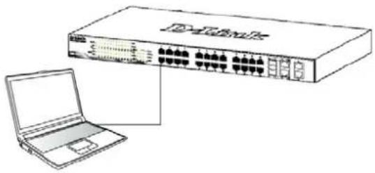
Step 1
Connect the Ethernet cable to any of the ports on the front panel of the switch and to the Ethernet port on the PC.
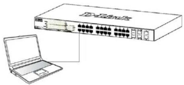
Figure 6. Connected Ethernet cable
Step 2
In order to login and configure the switch via an Ethernet connection, the PC must have an IP address in the same range as the switch. For example, if the switch has an IP address of 10.90.90.90, the PC should have an IP address of 10.x.y.z (where x/y is a number between 0 ~ 254 and z is a number between 1 ~ 254), and a subnet mask of 255.0.0.0.
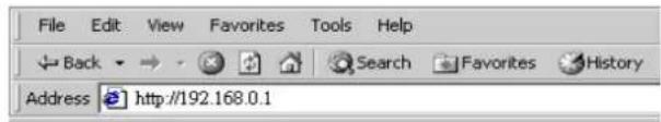
Open your web browser and enter http://10.90.90.90 (the factory-default IP address) in the address box. Then press
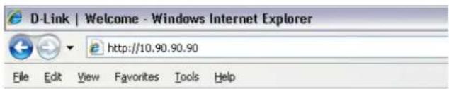
Figure 7. Enter the IP address 10.90.90.90 in the web browser
The web configuration can also be accessed through the SmartConsole Utility. Open the SmartConsole Utility and double-click the switch as it appears in the Device List. This will automatically load the web configuration in your web browser.

NOTE: The switch's factory default IP address is 10.90.90.90 with a subnet mask of 255.0.0.0 and a default gateway of 0.0.0.0
Step 3
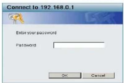
When the following logon box appears, enter "admin" for the password. Press OK to enter the main configuration window.
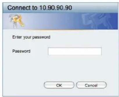
Figure 8. User authentication window
Step 4
Before entering the Web-based Management, the Smart Wizard will guide you to quickly configure some functions, such as Password Settings, SNMP Settings, and System Settings. If you don't plan to change
anything, click Exit to exit the Wizard and enter the Web-based Management. For a detailed look at the Smart Wizard's functions, please refer to the Smart Wizard introduction in the user manual.
SmartConsole Utility
The SmartConsole Utility included on the installation CD is a program for discovering Smart Switches with the same L2 network segment connected to your PC. This tool is only for computers running Windows 2000, Windows XP, and Windows Vista x64/86 operating systems. There are two options for the installation of SmartConsole Utility, one is through the autorun program on the installation CD and the other is manual installation.
Note: Please be sure to remove any existing SmartConsole Utility from your PC before installing the latest SmartConsole Utility.
Option 1: Follow these steps to install the SmartConsole Utility via the autorun program on the installation CD.
- Insert the Utility CD into your CD-Rom Drive.
- The autorun program will pop up automatically
- Simply click on the "Install SmartConsole Utility" button and an installation wizard will guide you through the process.
- After successfully installing the SmartConsole Utility, you can open the utility by clicking Start > Programs > D-Link SmartConsole Utility.
- Just connect the Smart Switch to the same L2 network segment of your PC and use the SmartConsole Utility to discover the Smart Switches.
Option 2: Follow these steps to install the SmartConsole Utility manually.
- Insert the Utility CD into your CD-Rom Drive.
- From the Standnu on the Windows desktop, choose Run.
- In the Run dialog box, type D:\D-Link SmartConsole Utility\setup.exe (where D:\ represents the drive letter of your CD-Rom) and click OK.
- Follow the on-screen instructions to install the utility.
- Upon completion, go to Start > Programs > D-Link SmartConsole Utility and open the SmartConsole Utility.
- Just connect the Smart Switch to the same L2 network segment of your PC and use the SmartConsole Utility to discover the Smart Switches.
For a detailed look at SmartConsole's functions, please refer to the SmartConsole Utility introduction in the user manual.
Telnet Management
Users may also access the switch through Telnet using your PC's Command Prompt. To access it from your computer, users must first ensure that a valid connection is made through the Ethernet port of the Switch and your PC, and then click Start > Programs > Accessories > Command Prompt on your computer. Once the console window opens, enter the command telnet 10.90.90.90 (depending on configured IP address) and press Enter on your keyboard. You should be directed to the opening console screen for the Command Line Interface of the switch, enter the "admin" for the default user name and password for the Switch and press the Enter key.
SNMP-Based Management
You can manage the Switch with D-Link D-View or any SNMP-compatible program. The SNMP function is default Disabled for D-Link Web Smart switches.
Additional Information
If you are encountering problems setting up your network, please refer to the user manual that came with the switch. It contains many more rules, charts, explanations, and examples to help you get your network up and running.
Additional help is available through our offices listed at the back of the user manual or online. To find out more about D-Link products or marketing information, please visit the website http://www.dlink.com.tw; for any support issue, please visit the website http://support.dlink.com.tw, which will re-direct you to appropriate local D-Link website.
Notes
Uber这意味着 Handbuch
SmartConsole Utility
3aTeM, nCNoIb3yB BnHTbI OT CToKn, 3akpeNtTe Ha Hei KOMMyTaTOP.
PncyHOK 3. YcTaHOBka KOMMyTaTopa B CtaHdApTHHyO CTOnKy
Waa 3- PooKJIouHeue Ka6eIa numaHua nepemEnHO2O moka
Ha daHHOM ware noKJIIOHnTe Ka6eJb nITaHnKa po3eTKe CETn nITaHn (KeNaTeNbHO 3a3EmJIeHHoN 3aunuehHoOn TepenadOB HapraKeHn).
PncyHok 4. NpoknOueHne KOMMyTaTopa K po3eTke
C6ou numaHua
B cnyuae c608 nHTAHnK KOMMyTaTOp DOnJKeH 6bItb OTKIOUeH. PpN BOCCTaHOBHeHn NHTAHn BKIOUHTe erO CHOBa.
ФункцuуynpaБленч
UnpaBHeNe KOMMyTaTopom D-Link cepu Web Smart MoKet OcyueCTBnTbC nOMOuI npToKoJa Telnet. MoXHo TaKke BbIbpaTb UnpaBHeNe Ha oCHOBe WebHTepFeInca, DocTyHoe uee3 Web-6pay3ep nnupe3 IIO60i KOMNbIOTep C NOMOuIy TUNlNTb SmartConsole.
Ecn Heo6xOJMo ynpabTb TOJbKO OdHIM KOMMyTaTopom D-Link Web Smart, yTuNtta Web-Based Management Utility BnIeTcnyuHm BbIbOpom. KaDbI KOMMyTaTop DOJXeH NOyUHTb CBoI IP-aDpec, KOtOpB I NcIOJIb3yeTcIy KOMMyHnKaUcN C yTuNtToI Web-Based Management Utility nIc MeHeJKePOM SNMP-ynpabJIeHnKOMNbIoTeP DOJXeH NMeTb IP-aDpec n3 TOrO Je dHaana30Ha, YTO IN KOMMyTaTop.
Ondako,ecnH Heo6xOIMO ynpabTbHeCKOJIbKIMN KOMMyTaTopamD-Link WebSmart,yTInNTa SmartConsole Utility aBnaetc npuMM Bbl6opom.C NOMOIOy TynITbI SmartConsole Utility He CneJyET MeHrtb IP-aDpec KOMNbIoTepa,ncce NOMOIO MOXHO JERKO Hauatb HacTpOky HeCKOJIbKINX KOMMyTaTOPOB cepin WebSmart. IoxaJynta,obpatntecb K CNeDyIOUIM NOpO6HbIM INHCTpyKlmaM NO yCTaHOBKe dJa Web-Based Management Utility n SmartConsole Utility,YnpabHeHHe Ha oCHOBe Telnet n SNMP.
YnpaBJIeHne Ha oCHObe Web-HTeppeica
Iocne ycneHOn yCTaHOKm MOxHo HaayTb HAcTpoKy KOMMyTaTopa, CneINTb 3a INDnKaTOpamn Ha NaHeN, n OTo6paKaTb rpaΦnueckyO cTaTnCTnky C nOmoBn Web -6pay3epa, TAKoT o Ka Netscape Navigator (BepCn 6.2 n Bblwe) nn Microsoft Internet Explorer (BepCn 5.0 n Bblwe).
ДЯ Web-н actpoKуctpoNCTBa Heo6xOdmo cnedyuOee o6OpyDObaHne:
KomnbIopet c pa3bemOM RJ-45 dne EthernetcoeHHeHn
- CtaHapThbI Ka6eIb Ethernet
Wae 1
IopKnHouNte Ka6enb Ethernet K IIO6Omy nopTy Ha nepeDHei naHn KOMMyTaTopa N K npTy Ethernet Ha KOMNbIoTepe.
Pncyok 6. PndknoueHne Ethernet-ka6ena
Wae 2
YTo6bI 3apeHCTpnpoBaTcBn HAcTpOnTb KOMMyTaTOp
Yepe3 Ethernet-coeINHeHne, Heo6xOJIMo Ha3HaHTb
KOMNbIoTepy IP-aDpec n3 TOrO JTo dNanap30Ha, YTo n IP-
aDpec KOMMyTaTopa. HanpImep, ecnn KOMMyTaTopy
npncBOeH IP-aDpec 10.90.90.90, To KOMNbIoTepy
Heo6xOJIMo npncBoNTb IP-aDpec BnDa 10.x.y.z (rDe
x/y - YnCna ot O do 254, a z - YnCno ot 1 do 254) n
Macky noDCETn 255.0.0.0.
PncyHOK 7. BBeDnTe IP-aDpec 10.90.90.90 B aDpeChOn CTpOke Web-6pay3epa
K Web-HaCTpoIke TaKKe MoXHo NOnyUHTb DoCTyn C NOMOuBIO yTINITb SmartConsole Utility. 3aNyCTnTe yTINITy SmartConsole Utility IN DBaJDbI HaxMITE Ha HYKHbIK KOMMyTaTOP n3 CNNCKa yCTPOINCTB. 3TO aBtOMaTHueckn 3arpy3NT Web-KoHpIpyaTOP B Web-6pay3epe.

ПРИМЕЧАНЕ:Ha
KOMMyTaTopaxNoумолчанIO
ncnoIb3yETcR IP-aIpeC
10.90.90.90 cMaCKoIpoDcTeN-255.0.0.0ишюзOMNo
ymoIaHIO-0.0.0
Wae 3
Nocne TOrO KaK NoaBnTcR OKHO pernctpaunu, BBeDnte "admin"B noIe napoi. HaxmTe OK dIy BXoJa B rnaBHoe OKHO KOHpyauu.
PucyHok 8. Okho ayTeHTnФнKaunIN ONIb3ObaTeJIa
Uae 4
Ipejde Yem nepeiTn B MeHIO Web-based Management (YnpabJIeHne Ha OCHOBE Web-INTepFeica), c nOmoIbIO MaCTepa yCTaHOBKn Smart Wizard BblNOJHNTe 6bICTpyo HAcTpoKny HeCKOJIbKnx FyHKuN, TaKx KaK Password Settings (HAcTpoKn napo), SNMP Settings (HAcTpoKn SNMP) n System Settings (HaCTpoKn CnCTembl). Ecnn n3MeHrTB 3TN HAcTpoKn Het Heo6XODIMOCtN, To HaxKMITE Exit (BblTu), UTO6bI BblTu n3 MaCTepa yCTaHOBKn I nepeiTu B MeHIO Web-based Management (YnpabJIeHne Ha OCHOBE WebHHTepFeieca). DnI nonUyeHn 6Oone noDpO6HoN INΦOpMaun o cyHKuNX MaCTepa yCTaHOBKn, NOXaNyIcTa, o6paTIteCb K COOTBeTCTByUoEMy pa3DeJy B PykoBOdCTBe nOJb3OBATeIa.
YtNiItaSmartConsole
yTnNTa SmartConsole, BKNIOUeHHa B yCTaHOBOHbI KOMnKaT-DNCK, RAIBAETcN porpAMMOI dIg O6HApJKeHnSMart-KOMMyTaTOPOB B ODNOM CeTEBOM CeMHe 2ypOBHn, NOKNIIOUeHHbIX K KOMNbIoTepy. DaHHyIO yTnNTyMOXH0 yCTaHOBNITb TOIbKO Ha KOMNbIoTepbI NODynpaBHeHnEM CNEdyUOxN OEPaUNOHbIX CnCTEm:Windows 2000, Windows XP n Windows Vista x64/86.ImeETcDba BapNaHTa yCTaHOBKn yTnNTbIMoSTConsole, nepBbI -Yepe3 nporpAMMy ABTO3aNyckaHa yCTaHOBOuHOM KOMnAKT-DINCKe N DpyRo -yCTaHOBKaBpyHyIO.
PpumeyaHue: Paped ycmaHOekou noCneDHeu eepcuu SmartConsole, noXaIyucma, y6edumecb e mom, ymo IIO6a cmapa eepcu ymuNumby SmartConsole ydaena u3 KOMNbIomepa.
Bapnant 1: CnejyTe 3a 3TmN waramn no yctahOBKe ytntbI SmartConsole uepe3 nporpamMy aBTO3arpy3Kn Ha yCTaHOBOUHOM KOMnakT-ndcKe.
- Пометитей компакт-дисту ТИЛТоь в пивор CD-ROM.
2.Прогамma aBTO3arpy3kn OTKpoETcA bBTOMaTHueCKn - HαχΜιTe Ha KΗΟΝΚy "Install SmartConsole Utility" (YγταHOBιMb yγΤΙΝΥ SmartConsole) έ MacTep yγCTaHOBΚn έροΒεδητ έχερε έροιες έγτaHOBΚn.
- Пocné OkOHuaHЯ yCTaHOBKn yTnJIHTbI SmartConsole MoXHo 3aNyCTuTb ee, HaxaB Ha NycK >ПporpamMbI >D-Link SmartConsole Utility.
Bapnant 2: CneyuTe 3Tm WaRam no yctahOBKe ytnntb SmartConsole BpyHyio.
- NomeCTHTe KOMnAaKT-DnCK C yTnIuToB B npNbOa CD-ROM.
-
Ⅰ3 MeHIO Nyck Ha pa6ooyem cToJe Windows, Bbl6epnte BbInonnHTb.
-
B DnAIOROBOM OKHe 3anyck nporpaMMbI, BBeDInTe D:\D-Link SmartConsole Utility\setup.exe (rJe D:\ -6ykbBa npVBOda CD-ROM) nHaXMMte OK.
- CneIyTe HNCTpyKzmaH Ha 3KpaHe dIy yCTaHOBKn yTINITbl.
- После заевшени установки, нахMuTe Пуск > ПорраммбI > D-Link SmartConsole Utility n 3anyctnte yTuNTy SmartConsole.
- ПОДКЛЮЧИТЕ KOMMYTaTOP Smart K TOMY JceCETeBOMy CeMenty 2 yPOBnH, YTO IN KOMNbIOTep,3aTEM NcNoJIb3yIte yTuNHTy SmartConsole nJaOBhApUKeHnA KOMMyTaTopoB Smart.
3a deTaJbHo nHΦopMauNei no ΦyHKUm yTnJntbl SmartConsole, noXaanyIcTa, o6paTntEcB K OINcaHIO yTnJntbl SmartConsole B pyKoBOdCTBe NOJIb3ObaTeJIa.
YnpabJIeHne Ha oCHObe Telnet
NoB3OBaTeJI MoryT TaKKe NOJyHTb DOCTyn K KomMyTaTopy Upe3 Telnet C NOMOuB KOMaHDoHOn CTPOKn. DnA DoCTyNa C KOMNbIOTepa NOLb3OBaTeJI, npExJe Bcero, Heo6XoIMMo y6eINTbcra B HaDeXHOM CoeINHeHH NOMMyTaTopa C KOMNbIOTePOM Upe3 NOpT Ethernet, 3aTeM HaxaTb Start (Nyck) > Programs (PporpAmMbI) > Accessories (CtAndapTHbe) > Command Prompt (KomAHnHa TcPOka). B OKHe KOHC0JI N BBeDInTE KOMaHdy telnet 10.90.90.90 (B 3aBNCMOCTn OT HAcTpoEHHOro IP-aDpeca) n HaxMNTe KHONKy Enter Ha KNabHaType. IpeenDInTe B OKHO KOHC0JI dIy YnpaBHeHH NOMOuBIO INHTepFeCa KOMaHDoH CTPOKn, BBeDInTe "admin" B KaueCTBe IMeHN IONb3OBaTeJI NO yMOJuaHnIO n napOJIb, a 3aTeM HaxMNTe KHONky Enter.
YnpaBJeHne Ha ochobe SNMP
YnpaBHeHne KOMMyTaTopom OcyuEcTBnReTc TaKke C NOMOsbIO DOnONHInTeNbHOro nporpaMMHO oBeCneHnra D-Link D-View nIIN IIOboI pyroI nporpaMMbI, COBmecTImoN c SNMP. Ha KOMMyTaTopax D-Link cepin Web Smart fynkun SNMP OTKnIOueHa no yMOnUaHHIO.
DononHumenbHa uHOpMaua
Pn BO3HKnHOBeHH NpO6JIem C HAcTpOuKoI CeTn, NOXaNyIcTa, O6paNTeCb K pyKOBoCTBy NOJb3ObaTeJIa, KOtOpoe BKNIOUeHO B KOMNJIeKT NocTaBKn KOMMyTaTopa. PyKOBOCTBO COepKNT MHOKeCTBO npaBn, DnArpaMM, O6bAcHeH N pnpMePoB dIra NOMOUs B HAcTpOuKe I 3anycke cTeN.
Долнельняnomoьdoctynha uepe3 ophcbl, nepeuNCHeHbIe B KOHcpe pyKOBoDCTBa NOb3OBaTeJIy IIN Yepe3 OHnaH. 3a noDpo6HoN INΦopMaUneiNo npOdyKtAm D-Link nIN MapKeTnHROB NnΦopMaUnei O6paTntecb, noXaNyIcTa, Ha Web-caIT http://www.dlink.ru, 3a lo6oIpyroN oDepxKoN -Ha Web-caIT http://dlink.ru/technical/index.php
Notes
關於本指南
SmartConsole Utility
SmartConsole Utility
SmartConsole Utility
- 1nSt-1uL CD to cOnbH-1oT o CD-ROM DlavI 7
2.才一トラが自動にスートしま�。