USER MANUAL STC1840EPCB BLACK & DECKER
natural_image
Line drawing of a hand using a screwdriver to adjust or install a mechanical component (no text or symbols visible)
natural_image
Illustration of a hand holding a medical device with a numbered label (83) on the wrist, no text or symbols present.
natural_image
Illustration of a hand using a tool to cut or mark a mechanical component (no text or symbols visible)

natural_image
Illustration of a hand using a tool to lift grass, with arrows indicating direction (no text or symbols)
natural_image
Illustration of a person using a shoveling machine in grass (no text or symbols)
2
3

natural_image
Technical line drawing of a mechanical device with a foot and lever assembly (no text or symbols)
natural_image
Illustration of a hand using a tool to press or adjust a mechanical component, with no visible text or symbols.
4
5
ENGLISH
(Original instructions)
Intended use
Your BLACK+DECKER STC1820E, STC1840E trimmers have been designed for trimming and finishing lawn edges and to cut grass in confined spaces. This appliance is intended for consumer use only.
Safety instructions
Warning! When using mains-powered appliances, basic safety precautions, including the following, should always be followed to reduce the risk of fire, electric shock, personal injury and material damage.
Warning! When using the machine the safety rules must be followed. For your own safety and bystanders please read these instructions before operating the machine. Please keep the instructions safe for later use.
- Read all of this manual carefully before operating the appliance.
- The intended use is described in this manual. The use of any accessory or attachment or the performance of any operation with this appliance other than those recommended in this instruction manual may present a risk of personal injury.
- Retain this manual for future reference.
Using your appliance
Always take care when using the appliance.
• Always use safety glasses or goggles.
- Never operate the machine while people, especially children, or pets are nearby.
- Do not allow children or animals to come near the work area or to touch the appliance.
- Close supervision is necessary when the appliance is used near children.
- This appliance is not intended for use by young or infirm persons without supervision.
- This appliance is not to be used as a toy.
- Only use the appliance in daylight or good artificial light.
- Use in a dry location only. Do not allow the appliance to become wet.
- Avoid using the appliance in bad weather conditions, especially when there is a risk of lightning.
- Do not immerse the appliance in water.
- Do not open the body casing. There are not user-serviceable parts inside.
- Do not operate the appliance in explosive atmospheres, such as in the presence of flammable liquids, gases or dust.
- The appliance is only to be used with the power supply unit provided with the appliance.
Safety of others.
- Never allow children, persons with reduced physical, sensory or mental capabilities or lack of experience and knowledge or people unfamiliar with these instructions to use the machine, local regulations may restrict the age of the operator.
- Children should be supervised to ensure that they do not play with the appliance.
Residual risks.
Additional residual risks may arise when using the tool which may not be included in the enclosed safety warnings. These risks can arise from misuse, prolonged use etc.
Even with the application of the relevant safety regulations and the implementation of safety devices, certain residual risks can not be avoided. These include:
- Injuries caused by touching any rotating/moving parts.
- Injuries caused when changing any parts, blades or accessories.
- Injuries caused by prolonged use of a tool. When using any tool for prolonged periods ensure you take regular breaks.
- Impairment of hearing.
- Health hazards caused by breathing dust developed when using your tool (example:- working with wood, especially oak, beech and MDF.)
After use
- When not in use, the appliance should be stored in a dry, well ventilated place out of reach of children.
- Children should not have access to stored appliances.
- When the appliance is stored or transported in a vehicle it should be placed in the boot or restrained to prevent movement following sudden changes in speed or direction.
Inspection and repairs
- Before use, check the appliance for damaged or defective parts. Check for breakage of parts and any
(Original instructions)
ENGLISH
other conditions that may affect its operation.
- Do not use the appliance if any part is damaged or defective.
- Have any damaged or defective parts repaired or replaced by an authorised repair agent.
- Never attempt to remove or replace any parts other than those specified in this manual.
Vibration
The declared vibration emission values stated in the technical data and the declaration of conformity have been measured in accordance with a standard test method provided by EN50636 and may be used for comparing one tool with another. The declared vibration emission value may also be used in a preliminary assessment of exposure.
Warning! The vibration emission value during actual use of the power tool can differ from the declared value depending on the ways in which the tool is used. The vibration level may increase above the level stated.
When assessing vibration exposure to determine safety measures required by 2002/44/EC to protect persons regularly using power tools in employment, an estimation of vibration exposure should consider, the actual conditions of use and the way the tool is used, including taking account of all parts of the operating cycle such as the times when the tool is switched off and when it is running idle in addition to the trigger time.
ENGLISH
(Original instructions)
Additional safety instructions for grass trimmers
Warning! Cutting elements continue to rotate after the motor is switched off.
- Be familiar with the controls and the proper use of the appliance.
• Always remove the battery from the appliance whenever the appliance is unattended, before clearing a blockage, before cleaning and maintenance, after striking a foreign object or whenever the appliance starts vibrating abnormally.
- Wear stout shoes or boots to protect your feet.
- Wear long trousers to protect your legs.
- Before using the appliance, check that your cutting path is free from sticks, stones, wire and any other obstacles.
- Only use the appliance in the upright position, with the cutting line near the ground. Never switch the appliance on in any other position.
- Move slowly when using the appliance. Be aware that freshly cut grass is damp and slippery.
- Do not work on steep slopes. Work across the face of slopes, not up and down.
- Never cross gravel paths or roads while the appliance is running.
- Never touch the cutting line while the appliance is running.
- Do not put the appliance down until the cutting line has come to a complete standstill.
- Use only the appropriate type of cutting line. Never use metal cutting line or fishing line.
- Be careful not to touch the line trimming blade.
- Keep hands and feet away from the cutting line at all times, especially when switching on the motor.
- Before using the appliance and after any impact, check for signs of wear or damage and repair as necessary.
- Never operate the appliance with damaged guards or without guards in place.
Take care against injury from any device fitted for trimming the filament line length. After extending new cutter line always return the machine to its normal operating position before switching on.
- Always ensure that the ventilation slots are kept clear of debris.
Additional safety instructions for batteries and chargers
Batteries
- Never attempt to open for any reason.
- Do not expose the battery to water.
- Do not store in locations where the temperature may exceed 40 °C.
- Charge only at ambient temperatures between 10 °C and 40 °C.
- Charge only using the charger provided with the tool.
- When disposing of batteries, follow the instructions given in the section "Protecting the environment".
Chargers
- Use your BLACK+DECKER charger only to charge the battery in the tool with which it was supplied. Other
batteries could burst, causing personal injury and damage.
- Never attempt to charge non-rechargeable batteries.
- Have defective cords replaced immediately.
- Do not expose the charger to water.
- Do not open the charger.
- Do not probe the charger.

The charger is intended for indoor use only.

Read the instruction manual before use.
Electrical safety
☐ Your charger is double insulated; therefore no earth wire is required. Always check that the mains voltage corresponds to the voltage on the rating plate. Never attempt to replace the charger unit with a regular mains plug.
- If the supply cord is damaged, it must be replaced by the manufacturer or an authorised BLACK+DECKER Service Centre in order to avoid a hazard.
Labels on appliance
The following pictograms are shown on the tool along with the date code:

Read the manual prior to operation.

Wear safety glasses or goggles when operating this appliance.

Wear suitable ear protectors when operating this appliance.
(Original instructions)
ENGLISH

Always remove the battery from the appliance before performing any cleaning or maintenance.

Beware of flying objects. Keep bystanders away from the cutting area.

Do not expose the appliance to rain or high humidity.

Directive 2000/14/EC guaranteed sound power.
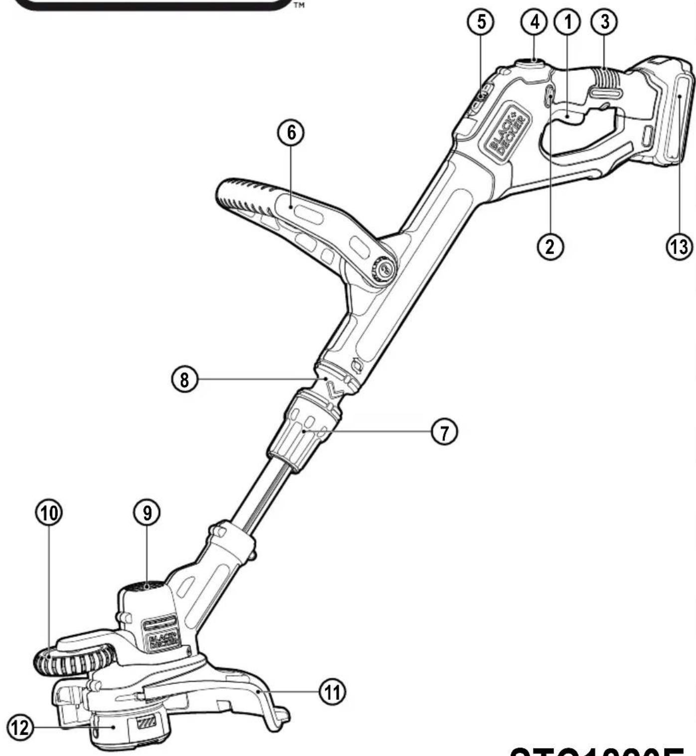
Features
This appliance includes some or all of the following features.
-
Trigger
-
Lock off button
-
Handle
-
POWERCOMMAND button
-
Auxiliary handle
-
Height adjust collar
-
Fliu to edge collar
-
Flip to edge dollar
-
Timeshead
-
Thimmer head
-
Edge wheel
-
Guard
-
Spool housing
-
Battery
-
Chamer
-
Charge indicator
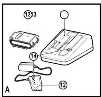
Charging the battery (Fig. A)
The battery needs to be charged before first use and whenever it fails to produce sufficient power on jobs that were easily done before.
The battery may become warm while charging; this is normal and does not indicate a problem.
Warning! Do not charge the battery at ambient temperatures below 10 °C or above 40 °C. Recommended charging temperature: approx. 24 °C.
Note: The charger will not charge a battery if the cell temperature is below approximately 10 °C or above 40 °C. The battery should be left in the charger and the charger will begin to charge automatically when the cell temperature warms up or cools down.
◆ Plug the charger into an appropriate outlet before inserting the battery pack.
◆ Insert the battery pack into the charger.
ENGLISH
(Original instructions)

The green LED will flash indicating that the battery is being charged.

The completion of charge is indicated by the green LED remaining on continuously. The pack is fully charged and may be used at this time or left in the charger
Warning! Recharge discharged batteries as soon as possible after use or battery life may be greatly diminished.
Charger diagnostics
This charger is designed to detect certain problems that can arise with the battery packs or the power source. Problems are indicated by one LED flashing in different patterns.
Bad Battery

The charger can detect a weak or damaged battery. The red LED flashes in the pattern indicated on the label. If you see this bad battery blink pattern, do not continue to charge the battery. Return it to a service centre or a collection site for recycling
Hot/Cold Pack Delay

When the charger detects a battery that is excessively hot or excessively cold, it automatically starts a Hot/Cold Pack delay, suspending charging until the battery has normalised. After this happens, the charger automatically switches to the Pack Charging mode. This feature ensures maximum battery life. The red LED flashes in the pattern indicated on the label when the Hot/Cold pack delay is detected.
Leaving the battery in the charger
The charger and battery pack can be left connected with the LED glowing indefinitely. The charger will keep the battery pack fresh and fully charged.
Important charging notes
-
Longest life and best performance can be obtained if the battery pack is charged when the air temperature is between 65°F and 75°F (18°-24°C). DO NOT charge the battery pack in an air temperature below +40°F (+4.5°C), or above +105°F (+40.5°C). This is important and will prevent serious damage to the battery pack.
The charger and battery pack may become warm to touch while charging. This is a normal condition, and does not indicate a problem. To facilitate the cooling of the battery pack after use, avoid placing the charger or battery pack in a warm environment such as in a metal shed, or an uninsulated trailer
◆ If the battery pack does not charge properly:
-
Check current at receptacle by plugging in a lamp or other appliance
◆ Check to see if receptacle is connected to a light switch which turns power off when you turn out the lights.
- Move charger and battery pack to a location where the surrounding air temperature is approximately 65°F - 75°F (18° - 24°C).
- If charging problems persist, take the appliance, battery pack and charger to your local service center.
The battery pack should be recharged when it fails to produce sufficient power on jobs which were easily done previously. DO NOT CONTINUE to use under these conditions. Follow the charging procedure. You may also charge a partially used pack whenever you desire with no adverse effect on the battery pack.
Foreign materials of a conductive nature such as, but not limited to, steel wool, aluminium foil, or any buildup of metallic particles should be kept away from charger cavities. Always unplug the charger from the power supply when there is no battery pack in the cavity. Unplug charger before attempting to clean.
- Do not freeze or immerse charger in water or any other liquid.
Warning! Shock hazard. Do not allow any liquid to get inside charger. Never attempt to open the battery pack for any reason.
If the plastic housing of the battery pack breaks or cracks, return to a service center for recycling.
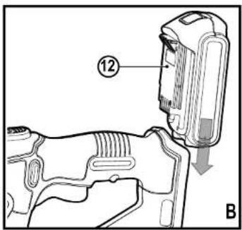
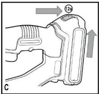
Installing and removing the battery pack from the appliance
Warning! Make certain the lock-off button is not engaged to prevent switch actuation before removing or installing battery
To install battery pack
Insert battery (12) into appliance until an audible click is heard (Figure B). Ensure battery pack is fully seated and fully latched into position.
To remove battery pack
Depress the battery release button (12a) as shown in Figure C and pull battery pack out of appliance.
Assembly
Warning! Before assembly, make sure that the tool is switched off and the battery has been removed.
Assembly tools required (not supplied):
Phillips Screwdriver.
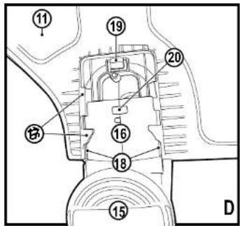
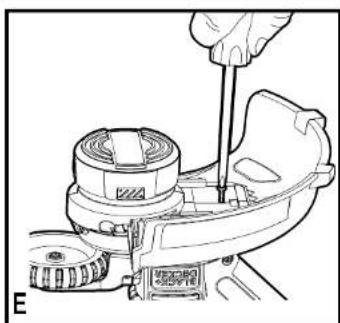
Fitting the guard (Fig. D, E)
Warning! Remove the battery from the appliance before attempting to attach the guard, edge guide or handle. Never operate appliance without guard firmly in place. The guard must always be on the appliance to protect the user.
◆ Remove the screw from the guard.
◆ Tum the trimmer upside down so that you are looking down at the spool cap (15).
- Tum the guard (10) upside down and slide it fully onto the motor housing (16). Make sure the tabs (17) on the guard engage the ribs (18) on the motor housing as shown.
◆ Continue to slide the guard on until you hear it 'snap' into place. The locking tab (19) should snap into the housing slot (20).
- Using a phillips screwdriver, insert the guard screw and tighten securely as shown in Figure E to complete the guard assembly.
- Once the guard is installed, remove the covering from the line cut-off blade, located on the edge of the guard
Warning! Never use the tool unless the guard is properly fitted.
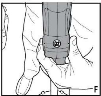
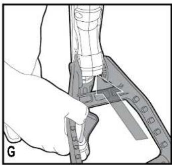
Attaching the auxiliary handle (Fig. F, G, H)
◆ To attach the handle, press in on the buttons (21) on both sides of the upper housing as shown in Figure F.
◆ Position the handle as shown in Figure G (with the BLACK+DECKER logo facing upward). Partially push the handle on so it will hold the buttons in when you release them with your hand.
◆ Push the handle completely onto the housing and position it slightly until it "snaps" into place.
◆ To adjust the handle up or down, press in on the button (22) and raise or lower the handle (Figure H).
◆ The handle should be adjusted so that your front arm is straight when the trimmer is in the working position.
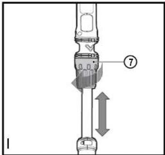
Height adjustment (Fig. I, J–J3)
Warning! Adjust the length of the trimmer to obtain proper working positions shown in Figures J - J3.
The overall height of the trimmer can be adjusted by loosening the height-adjust collar (6) by rotating it in the direction of the arrow shown in Figure 1.
(Original instructions)
ENGLISH
- Move the upper housing straight up or down. When the desired height is achieved, tighten the collar by rotating it opposite of the direction shown in Figure 1.
Releasing the cutting line
In transit, the cutting line is taped to the spool housing.
- Remove the tape holding the cutting line to the spool housing.
Operation
Warning! Always use proper eye protection.
Warning! Before you begin trimming, only use the appropriate type of cutting line.
Note: Inspect area to be trimmed and remove any wire, cord, or string-like objects which could become entangled in the rotating line or spool. Be particularly careful to avoid any wire which might be bent outwardly into the path of the appliance, such as barbs at the base of a chain link fence.
Switching on and off
- To switch the appliance on, push the lock-off button (2), and squeeze the trigger (1).
◆ To switch the appliance off, release the trigger.
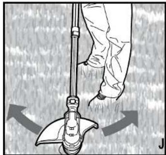
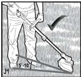
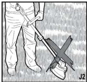
Operating the trimmer (Fig. I, J–J3)
With the unit on, angle unit and slowly swing the trimmer side to side as shown in Figure J.
- Maintain a cutting angle of 5° to 10° as shown in Figure J1. Do not exceed 10° (Figure J2). Cut with the tip of the line. To keep distance from hard surfaces use edge wheel (9).
- Maintain a minimum distance of 60 cm between the guard and your feet as shown in Figure J3. To achieve this distance adjust the overall height of the trimmer as shown in Figure I.
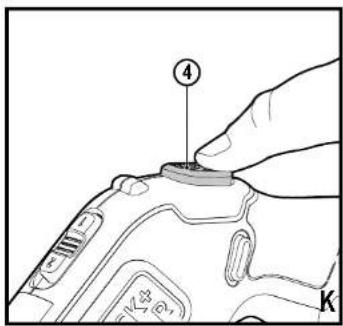
The POWERCOMMAND feature allows you to advance the length of cutting line available while trimming.
◆ To extend the cutting line, fully depress the
POWERCOMMAND button (4) while trimming and then release (figure K).
Note: The trimmer will stop cutting when the
POWERCOMMAND button is pressed and will resume cutting when released.
- For maximum line length, press the button multiple times until you hear the cutting line hitting the guard.
Note: Do not continue to press the POWERCOMMAND button once the maximum length is reached. This will result in overfeeding and will consume string quickly.
ENGLISH
(Original instructions)
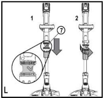
Convert to edging mode (Fig. L, M)
Warning! The wheeled edge guide should only be used when in the edging mode.
The trimmer can be used in trimming mode or edging mode to trim overhanging grass along lawn edges and flower beds. For edging, the trimmer head should be in the position shown in Figure M. If it is not:
◆ Remove the battery from the trimmer.
- Grasp the flip-to-edge collar (7) and push down as shown in part 1 of Figure L.
- Rotate the flip-to-edge collar 180° counterclockwise as shown in part 2, until the handle snaps back into the upper half of the trimmer.
- To return to trimming position, pull the flip-to-edge collar down and rotate the head clockwise back to its original position.
Note: You will experience faster than normal cutting line wear if the trimmer line is positioned directly over the sidewalk or abrasive surface.
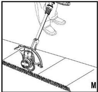
Edging (Fig. M)
Warning! When being used as an Edger, stones, pieces of metal and other objects can be thrown out at high speed by the line. The trimmer and guard are designed to reduce the danger. However, MAKE SURE that other persons and pets are at least 30 m away. Optimum cutting results are achieved on edges deeper than 50 mm.
◆ Do not use this trimmer to create trenches.
◆ Using the edging wheel (9), guide the trimmer as shown in Figure M.
◆ Position the edging wheel on the edge of the sidewalk or abrasive surface so the cutting line is over the grass or dirt area to be edged.
◆ To make a closer cut, slightly tilt the trimmer.
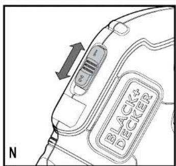
Speed control & runtime extension mode (Fig. N)
This string trimmer gives you the choice to operate at a more efficient speed to extend the runtime for larger jobs, or accelerate the trimmer speed for high-performance cutting (Figure N).
- To extend runtime, pull the speed-control switch back toward the battery (12) into position #1. This mode is best for larger projects that require more time to complete.
To accelerate the trimmer, push the speed-control switch forward toward the trimmer head (8) into position #2. This mode is best to cut through heavier growth and for applications that need higher RPM.
Note: When in acceleration mode (#2), runtime will be decreased as compared to when trimmer is in extended runtime mode (#1).
Helpful cutting tips
Use the tip of the string to do the cutting; do not force string head into uncut grass. Use edge guide along such things as fences, houses and flower beds for best practices.
- Wire and picket fences cause extra string wear, even breakage. Stone and brick walls, curbs, and wood may wear string rapidly.
- Do not allow spool cap to drag on ground or other surfaces.
◆ In long growth cut from the top down and do not exceed 300 mm high.
- Keep trimmer tilted toward the area being cut; this is the best cutting area.
◆ The trimmer cuts when passing the unit from the right to left. This will avoid throwing debris at the operator.
- Avoid trees and shrubs. Tree bark, wood moldings, siding, and fence posts can easily be damaged by the string.
Cutting line / line feeding
Your trimmer uses 1.65 mm diameter, Round nylon line. During use, the tips of the nylon lines will become frayed and worn and the special self feeding spool will automatically feed and trim a fresh length of line. Cutting line will wear faster and require more feeding if the cutting or edging is done along sidewalks or other abrasive surfaces or heavier weeds are being cut. The advanced automatic line feeding mechanism senses when more cutting line is needed and feeds and trims the correct length of line whenever it's required. Do not bump unit on ground in attempt to feed line or for any other purposes.
Warning! Remove the battery from the trimmer before making any assembly, adjustments or changing accessories. Such preventive safety measures reduce the risk of starting the appliance accidentally. From time to time, especially when cutting thick or stalky weeds, the line feeding hub may become clogged with sap or other material and the line will become jammed as a result. To clear the jam, follow the steps listed below.
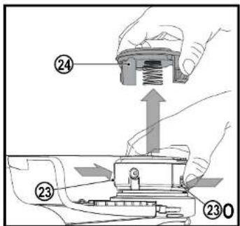
◆ Remove the battery from the trimmer.
- Press the release tabs (23) on the line spool cap (24), as shown in Figure O and remove the cap by pulling it straight off.
◆ Pull the nylon line spool out and clear any broken line or cutting debris from the spool area.
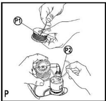
- Place spool and line into spool cap with line "parked" in slots provided as shown in Figure P1.
- Insert the line end through the appropriate hole in the spool housing. Pull slack line through until it pulls out of the holding slots as shown in Figure P2.
- Press the spool down gently and rotate it until you feel it drop into place and then push to snap into place. (When in place, the spool will turn a few degrees left and right freely).
Take care to keep the line from becoming trapped under the spool.
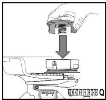
◆ Align the spool cap tabs with the slots on the spool housing.
◆ Snap the spool cap back on as shown in Figure Q by depressing lugs and pressing into spool housing.
Note: Make sure that cover is fully positioned, listen for two audible clicks to ensure both lugs are correctly located. Power the appliance on. In a few seconds or less you'll hear the nylon line being cut automatically to the proper length.
Warning! To avoid appliance damage, if the cutting line protrudes beyond the trimming blade, cut it off so that it just reaches the blade.
Note: Other replacement parts (guards, spool caps, etc.) are available through BLACK+DECKER service centers. To find your local service location visit www.blackanddecker.com. Warning! The use of any accessory not recommended by BLACK+DECKER for use with this appliance could be hazardous.
Replacing the spool (Fig. O, P, Q, R)
◆ Remove battery from appliance.
◆ Depress the tabs (23) and remove the spool cap (24) from the spool housing (11) (Figure O).
◆ Grasp empty spool with one hand and spool housing with other hand and pull spool out.
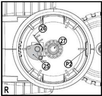
- If lever (25) or spring (26) in base of housing (Figure R) becomes dislodged, replace in correct position before inserting new spool into housing.
◆ Remove any dirt and grass from the spool and housing.
◆ Unfasten the end of the cutting line and guide the line into the eyelet (P2) Figure P.
Take the new spool and push it onto the boss (27) (Figure R) in the housing. Rotate the spool slightly until it is seated. The line should protrude approximately 136 mm from the housing.
♦ Align the tabs on the spool cap with the slots in the housing (Figure Q).
◆ Push the cap onto the housing until it snaps securely into place.
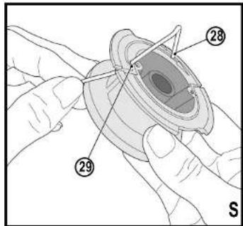
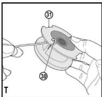
Rewinding spool from bulk line (Fig. S, T, U)
Bulk line is also available for purchase from your local retailer. Note: Hand wound spools from bulk line are likely to become tangled more frequently than BLACK+DECKER factory wound spools. For best results, factory wound spools are recommended. To install bulk line, follow the steps below:
◆ Remove battery from appliance.
(Original instructions)
ENGLISH
- Remove the empty spool from the appliance as described in "Replacing the spool."
◆ Remove any remaining cutting line from the spool.
◆ Make a fold at the end of the cutting line at about 19 mm (28). Feed the cutting line into one of the line anchoring slots (29) as shown in Figure S.
- Insert the 19 mm end of the bulk line into the hole (30) in the spool adjacent to the slot as shown in Figure T. Make sure the line is pulled tight against the spool as shown in Figure T.
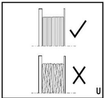
- Wind the cutting line onto the spool in the direction of the arrow on the spool. Make sure to wind the line on neatly and in layers. Do not crisscross (Figure U).
- When the wound cutting line reaches the recesses (31), cut the line (Figure T).
- Fit the spool onto the appliance as described in "Replacing the spool".
Maintenance
Your BLACK+DECKER corded/cordless appliance/tool has been designed to operate over a long period of time with a minimum of maintenance. Continuous satisfactory operation depends upon proper tool/appliance care and regular cleaning.
Your charger does not require any maintenance apart from regular cleaning.
Warning! Before performing any maintenance on corded/cordless power tools:
◆ Switch off and unplug the appliance/tool.
- Or switch off and remove the battery from the appliance/tool if the appliance/tool has a separate battery pack.
- Or run the battery down completely if it is integral and then switch off.
◆ Unplug the charger before cleaning it. Your charger does not require any maintenance apart from regular cleaning.
- Regularly clean the ventilation slots in your tool/appliance and charger using a soft brush or dry cloth.
◆ Regularly clean the motor housing using a damp cloth. Do not use any abrasive or solvent-based cleaner.
- Regularly clean the cutting line and spool using a soft brush or dry cloth.
◆ Regularly use a blunt scraper to remove grass and dirt from the underneath of the guard.
ENGLISH
(Original instructions)
Troubleshooting
| Problem | Solution |
| Appliance runs slowly. Remove battery from Inhims. | Check that the spool housing can rotate freely. Carefully clean if it necessary. |
| Check that the cutting line does not promote more than approximately 122 mm from the spool. If it does, cut it off so it just reaches the line trimming blade. |
| Automatic line feed does not feed line. | More line is fed when the line shortens to approximately 70 mm. To determine if the line is not feeding, let the wear past this point. |
| Keep the tabs depressed and remove the spotscap with the spool from the spool housing in the summer head. |
| Ensure that the line is not disprocessed on the spool as celtated in Fig. 10. If it is unwind the cutting line and reweighted lineally. |
| Inspect tracks at the bottom of spool for damage. If damaged, replace spool. |
| Pull the cutting line until it protrudes approximately 122 mm from the spool. If insufficient cutting line is left on the spool, install a new spool of cutting line. Align the sides on the spool cap with the cut cuts in the housing. Push the spool cap onto the housing until it ensures securely into plane. If the cutting line protrudes beyond the trimming place, put it off so that just reaches the blade. If the automatic line feed still does not work or the spool is jammed, try the following suggestions: Carefully clean the spool and housing. Make sure you are using correct the size and diameter (2.30 mm) - smaller and larger line sizes will affect the functionality of the auto-feed system. Remove the spool and check the lever in the spool housing can move freely. Remove the spool and unwind the cutting line, then wind it on neatly again. Replace the spool into the housing. |
| Overfeeding Ensure you are cutting | with the tip of the line 1.77 mm from the spool. Use the edge guide if needed to ensure proper spool is maintained. Ensure you are not exceeding a 12 angle as shown in Fig. JII. Avoid contact of the line with hero surfaces such as brick, concrete, wood etc. This will prevent excessive waste and/or overload of line. Cut with the tip of the line |
| Line unravels when cap or spool is removed | Main sums to park the lines in holding spots irrigate fly before remoing. |
Protecting the environment
Separate collection. Products and batteries marked with this symbol must not be disposed of with normal household waste.
Products and batteries contain materials that can be recovered or recycled reducing the demand for raw materials. Please recycle electrical products and batteries according to local provisions. Further information is available at www.2helpU.com
Technical data
| | STC1620E |
| Input Voltage | V_DC | 18 |
| No-Load Speed | min ^-1 | 5300 - 7400 |
| Weight | kg 2.1 | |
| | STC1840E |
| Input Voltage | V_DC | 15 |
| No-Load Speed | min ^-1 | 6300 - 7200 |
| Weight | kg 2.1 | |
| Battery BL2018 - STC18 | 20E | |
| Voltage | V_DC | 16V |
| Capacity An | | 2.0 |
| Type Li-ion | | |
| Battery BL4018 - STC18 40E | |
| Voltage | V_DC | 16V |
| Capacity Ah | | 4.0 |
| Type Li-Ion | | |
| Charger | | 905002** (Type 1) | 905008** 905008** |
| Input Voltage | V_DC | 100-240V 230V | 230V | |
| Output Voltage | V_DC | 18V 18V 16V | | |
| Current mA 40Ω | | 1000 | 2000 | |
Hand/arm weighted vibration value according to EN50636-2-91:
= < 2,5m / s^2 uncertainty (K) = 1,5m / s^2
L_FA (sound pressure) 79 dB(A)
uncertainty (K) = 3 dB(A)
(Original instructions)
ENGLISH
MACHINERY DIRECTIVE OUTDOOR NOISE DIRECTIVE

STC1820E, STC1840E Cordless String Trimmer
Black & Decker declares that these products described under
"technical data" are in compliance with: 2006/42/EC, EN60335-1:2012 + A11:2014 EN50636-2-91:2014
2000/14/EC, Lawn Trimmer, L ≤ 50 cm, Annex VI
DEKRA Certification B.V., Utrechtseweg 310
6802 ED Amhem, The Netherlands
Notified Body ID No.: 0344
Level of sound power according to 2000/14/EC
(Article 12, Annex III, L ≤ 50 cm): L_ww (measured sound power) 93 dB(A)
uncertainty (K) = 3 dB(A) L_ww (guaranteed sound power) 96 dB(A)
These products also comply with Directive 2014/108/EC (until
9.04.2016). 2014/30/EU (from 20.04.2016) and 2011/65/EU
For more information, please contact Black & Decker at the
following address or refer to the back of the manual
The undersigned is responsible for compilation of the technical
file and makes this declaration on behalf of Black & Decker.

R. Laverick
Director of Engineering
Black & Decker Europe, 210 Bath Road, Slough,
Berkshire, SL1 3YD
United Kingdom
13/11/2015
Guarantee
Black & Decker is confident of the quality of its products and offers consumers a 24 month guarantee from the date of purchase. This guarantee is in addition to and in no way prejudices your statutory rights. The guarantee is valid within the territories of the Member States of the European Union and the European Free Trade Area.
To claim on the guarantee, the claim must be in accordance with Black&Decker Terms and Conditions and you will need to submit proof of purchase to the seller or an authorised repair agent. Terms and conditions of the Black&Decker 2 year guarantee and the location of your nearest authorised repair agent can be obtained on the Internet at www.2helpU.com, or by contacting your local Black & Decker office at the address indicated in this manual.
Please visit our website www.blackanddecker.co.uk to register your new Black & Decker product and receive updates on new products and special offers.
DEUTSCH
STC1820E, STC1840E Rasentrimmer
Director of Engineering
Black & Decker Europe, 210 Bath Road, Slough,
Berkshire, SL1 3YD
Coupe-bordure STC1820E, STC1840E
Tagliabordi a filo cordless STC1820E, STC1840E
Black & Decker Europe, 210 Bath Road, Slough,
Berkshire, SL1 3YD
Regno Unito
10.11.2015
STC1820E, STC1840E, Draadtrimmer
Director of Engineering
Black & Decker Europe, 210 Bath Road, Slough,
Berkshire, SL1 3YD
Verenigd Koninkrijk
10.11.2015
Black & Decker Europa, 210 Bath Road, Slough,
Berkshire, SL1 3YD
Reino Unido
10.11.2015
Garantía
Director de Engenharia
Black & Decker Europe, 210 Bath Road, Slough,
Berkshire, SL1 3YD
Reino Unido
10.11.2015
small organ, id-nr: 0344
Den akustiska effekten enligt 2000/14/EG (Artikel 12, Annex III, L ≤ 50 cm):
L_HfA (uppmätt ljudeffekt) 93 dB(A)
osäkerhet (K) = 3 dB(A)
L_w (garanterad ljudniva) 96 dB(A)
Director of Engineering
Black & Decker Europe, 210 Bath Road, Slough,
Berkshire, SL1 3YD
Storbritannien
10.11.2015
STC1820E, STC1840E, trádtrimmer
Director of Engineering
Black & Decker Europe, 210 Bath Road, Slough,
Berkshire, SL1 3YD
Storbritannia
10.11.2015
Garanti
STC1820E, STC1840E, graestrimmer
Black & Decker Europe, 210 Bath Road, Slough.
Berkshire, SL1 3YD
Storbritannien
10.11.2015
Garanti
STC1820E, STC1840E, Trimmeri
Black & Decker Europe, 210 Bath Road, Slough,
Berkshire, SL1 3YD
Iso-Britannia
10.11.2015
Takuu
6802 ED Amhem, The Netherlands
Black & Decker Europe, 210 Bath Road, Slough,
Berkshire, SL1 3YD
United Kingdom
10.11.2015
Εγγύηση
H Black & Decker eivala siyoujon via the niosiopitana twni propo-iviviums tns kai trosopefraci oiosus katavamoktes evyvupotn 24 umvov anto the nyueroomynia ayorapás. Aunl h evyvupotn elvai propoereto dikaloaksa zas kevi dev zymiuovei ta vóvijma deikawo-mató aos. H evyvupotn icybei evtács the inciprataics twn yuvipwem melów tns Eurwattaičsk Evuwtans kai tns Eurwattaičsk Zówins Elecëbrów Suvaualkayów. Για van uopolbaste afisjων δασει tns evyvupotns, η αξίωση κα τρεπετι va elvai suφωρων με toos 'Orocus kan proumođeševis tns Black&Decker kαι θα χρειαστεί van uopolbaste antódeih avyorapás aton πωλητή ή σε εξομισοδο-tnýevo antiπρόσυτο επίσκεων.
service.austria@sbdinc.com
Portugal Black & Decker Limited SARL Tel. 214667500
emeaservice@sbdinc.com
Middle East & Africa Black & Decker Tel. +971 4 8863030
www.blackanddecker.ae P.O.Box - 17164 Fax +971 4 8863333
service.mea@sbdinc.com Jebel Ali Free Zone (South), Dubai,
UAE