SH 30 S - Boiler STIEBEL ELTRON - Free user manual and instructions
Find the device manual for free SH 30 S STIEBEL ELTRON in PDF.
| Product type | Electric storage water heater, pressurized or free-flow |
| Brand | Stiebel Eltron |
| Model | SH 30 S |
| Nominal capacity | 30 liters |
| Dimensions (H x W x D) | 770 x 410 x 420 mm |
| Net weight | 23.1 kg |
| Weight with water | 53 kg |
| Connected load (230 V) | 1 to 4 kW (adjustable) |
| Connected load (400 V 3-phase) | 3 to 6 kW (adjustable) |
| Rated voltage | 230/400 V, 50 Hz |
| Temperature setting range | 35 °C to 82 °C |
| Maximum permissible pressure | 0.6 MPa (6 bar) |
| Maximum flow rate | 18 l/min |
| Energy efficiency class | B |
| Mixed water volume at 40 °C (65 °C/15 °C) | 59 liters |
| Standby consumption/24h at 65 °C | 0.46 kWh |
| Protection rating | IP25 |
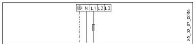
| Hydraulic connection | Male thread G 1/2 A (cold water inlet and DHW outlet) |
| Main functions | Automatic heating, frost protection, continuous temperature adjustment, heating capacity display, operation indicator, SERVICE ANODE indicator |
| Safety | Safety valve, safety limiter, corrosion protection indicator anode, residual current device recommended |
| Maintenance and cleaning | Cleaning with a damp cloth, regular descaling of the heating element, periodic check of the safety valve |
| Spare parts and repairability | Indicator anode, heating element, thermostat, regulation-limiter assembly; original parts recommended |
| Warranty | According to the conditions of the local subsidiary; manufacturer guarantee for devices purchased in Germany |
Frequently Asked Questions - SH 30 S STIEBEL ELTRON
User questions about SH 30 S STIEBEL ELTRON
0 question about this device. Answer the ones you know or ask your own.
Ask a new question about this device
Download the instructions for your Boiler in PDF format for free! Find your manual SH 30 S - STIEBEL ELTRON and take your electronic device back in hand. On this page are published all the documents necessary for the use of your device. SH 30 S by STIEBEL ELTRON.
USER MANUAL SH 30 S STIEBEL ELTRON

www.stiebel-eltron.com/registration
INSTALLATION
8. Sicherheit
SH 50 - 150 S (G 3 / 4
- General information 16
1.1 Safety instructions 16
1.2 Other symbols in this documentation 16
1.3 Units of measurement 16 - Safety 16
2.1 Intended use 16
2.2 General safety instructions 16
2.3 Test symbols 17 - Appliance description 17
3.1 Frost protection 17 - Settings 17
- Cleaning, care and maintenance 17
- Troubleshooting 18
INSTALLATION
- Safety 18
7.1 General safety instructions 18
7.2 Instructions, standards and regulations 18 - Appliance description 18
8.1 Standard delivery 18
8.2 Accessories 18
9.Preparations 18
9.1 Installation site 18
9.2 Fitting the wall mounting bracket 18
9.3 Preparing the connecting cables 19 - Installation 19
10.1 Water connection 19
10.2 Appliance installation 19
10.3 Power supply 20 - Commissioning 20
11.1 Commissioning 20
11.2 Recommissioning 20 - Settings 21
- Shutting down 21
- Troubleshooting 21
- Maintenance 22
15.1 Checking the safety valve 22
15.2 Draining the appliance 22
15.3 Checking / replacing the signal anode 22
15.4 Dcscaling 22
15.5 Anti-corrosion protection 22 - Specification 23
16.1 Dimensions and connections 23
16.2 Wiring diagrams and terminals 24
16.3 Heat-up diagram 25
16.4 Fault conditions 25
16.5 Details on energy consumption 25
16.6 Data table 26
GUARANTEE
ENVIRONMENT AND RECYCLING
SPECIAL INFORMATION
- The appliance may be used by children aged 3 and up and persons with reduced physical, sensory or mental capabilities or a lack of experience and know-how, provided that they are supervised or they have been instructed on how to use the appliance safely and have understood the resulting risks. Aged 3 to 8 years are only allowed to operate the tap connected to the appliance. Children must never play with the appliance. Children must never clean the appliance or perform user maintenance unless they are supervised.
- The connection to the power supply is only permissible as a permanent connection in conjunction with the removable cable grommet. Ensure the appliance can be separated from the power supply by an isolator that disconnects all poles with at least 3mm contact separation.
- Secure the appliance as described in chapters "Installation / Preparations" and "Installation / Installation / Appliance installation".
- Observe the minimum and maximum water inlet pressure (see chapter "Installation /Specification / Data table").
- Drain the appliance as described in the chapter "Installation / Maintenance / Draining the appliance".
Install a residual current device (RCD).
Sealed unvented operating mode:
- The appliance is under pressure. During the heat-up process, expansion water will drip from the safety valve.
- Regularly activate the safety valve to prevent it from becoming blocked, e.g. by limescale deposits.
- Install a type-tested safety valve in the cold water supply line. Please note that, depending on the static pressure, you may also need a pressure reducing valve.
- Size the drain so that water can drain off unimpeded when the safety valve is fully opened.
-
Fit the discharge pipe of the safety valve with a constant downward slope and in a room free from the risk of frost.
-
The safety valve discharge aperture must remain open to the atmosphere.
OPERATION
1. General information
The chapter "Operation" is intended for appliance users and qualified contractors.
The chapter "Installation" is intended for qualified contractors.

Note
Read these instructions carefully before using the appliance and retain them for future reference.
Pass on the instructions to a new user if required.
1.1 Safety instructions
1.1.1 Structure of safety instructions

KEYWORD Type of risk
Here, possible consequences are listed that may result from failure to observe the safety instructions.
Steps to prevent the risk are listed.
1.1.2 Symbols, type of risk
Symbol Type of risk

Injury

Electrocution

Burns
(burns, scalding)
1.1.3 Keywords
KEYWORD Meaning
DANGER Failure to observe this information will result in serious injury or death.
WARNING Failure to observe this information may result in serious injury or death.
CAUTION Failure to observe this information may result in non-serious or minor injury.
1.2 Other symbols in this documentation

Note
General information is identified by the symbol shown on the left.
Read these texts carefully.
Symbol Meaning

Material losses
(appliance, consequential and environmental losses)

Appliance disposal
This symbol indicates that you have to do something. The action you need to take is described step by step.
1.3 Units of measurement

Note
All measurements are given in mm unless stated otherwise.
2. Safety
2.1 Intended use
This appliance is designed to heat DHW. The appliance can supply one - or, in sealed unvented (pressurised) mode - several draw-off points.
This appliance is intended for domestic use. It can be used safely by untrained persons. The appliance can also be used in a non-domestic environment, e.g. in a small business, as long as it is used in the same way.
Any other use beyond that described shall be deemed inappropriate. Using the appliance for heating fluids other than water or for water supplemented with chemicals, such as brine, is also deemed inappropriate.
Observation of these instructions and of instructions for any accessories used is also part of the correct use of this appliance.
2.2 General safety instructions

WARNING Burns
During operation, the valve and safety assembly can reach temperatures in excess of 60^ .
There is a risk of scalding at outlet temperatures in excess of 43^ .

WARNING Injury
The appliance may be used by children aged 3 and up and persons with reduced physical, sensory or mental capabilities or a lack of experience and know-how, provided that they are supervised or they have been instructed on how to use the appliance safely and have understood the resulting risks. Aged 3 to 8 years are only allowed to operate the tap connected to the appliance. Children must never play with the appliance. Children must never clean the appliance or perform user maintenance unless they are supervised.

Material losses
Protect the water lines and the safety assembly against frost.

Note
Sealed unvented operating mode: The appliance is under pressure. During the heat-up process, expansion water will drip from the safety valve.
If water continues to drip when heating is completed, please inform your qualified contractor. Open vented operating mode: Whenever water is heated up, expansion water will drip from the spout.
2.3 Test symbols
See type plate on the appliance.
3. Appliance description
The appliance heats domestic hot water electrically, in line with the connected heating output. You can adjust the temperature using the temperature selector. Subject to the power supply, the water is automatically heated to the required temperature. The currently available heat content is displayed.
The appliance is suitable for both open vented (non-pressurised) and sealed unvented (pressurised) operation.
The internal steel cylinder is coated in special directly applied "anticor" enamel and equipped with a signal anode. The anode with consumption indicator protects the cylinder interior from corrosion.
3.1 Frost protection
The appliance is also protected against frost on the temperature setting "cold", as long as the power supply is guaranteed. The appliance switches on in good time and heats the water. The appliance does not protect the water supply lines and the safety assembly against frost.
4. Settings
The temperature can be freely adjusted.
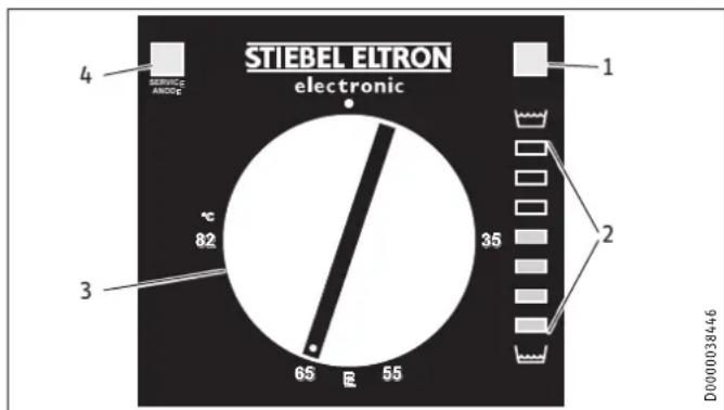
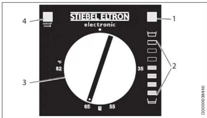
1 ON/OFF indicator
2 Heat content indicator
3 Temperature selector
4 SERVICE ANODE indicator
Cold
E Recommended energy saving position, low scaling, 60^
82°C Maximum temperature setting
Depending on the system, the actual temperatures may vary from the set value.
SERVICE ANODE indicator
Sealed unvented operating mode:

Material losses
Sealed unvented operating mode:
- Notify your qualified contractor if the SERVICE ANODE indicator illuminates.
Open vented operating mode:

Note
In open vented operation, the SERVICE ANODE indicator has no function.
Check the protective anode after the first 2 years of use and replace if necessary.
ON/OFF indicator
The ON/OFF indicator illuminates when water is being heated.
Heat content indicator
The display shows the currently available amount of mixed water at 40^ , with a cold water temperature of 15^ and a temperature setting of 65^ . The number of lights indicates the minimum available volume of mixed water at 40^ .
This enables you to match the temperature setting to your draw-off pattern to ensure optimum efficiency and save energy. We recommend you initially set the temperature to 65^ . If more than one indicator remains illuminated when your maximum draw-off volume is reached you can lower the set temperature.
| SH 30 S | 10 | 20 | 30 | 40 | 50 | 60 | 75 |
| SH 50 S | 13 | 30 | 45 | 65 | 80 | 100 | 125 |
| SH 80 S | 20 | 50 | 75 | 100 | 130 | 160 | 200 |
| SH 100 S | 25 | 60 | 90 | 130 | 160 | 200 | 250 |
| SH 120 S | 30 | 70 | 110 | 155 | 195 | 235 | 300 |
| SH 150 S | 40 | 90 | 135 | 190 | 240 | 295 | 370 |
| DHW demand, mixed water volume 40 °C | |||||||
| Bath | 120-150 | ||||||
| Shower | 30-50 | ||||||
| Hand washing | 2-5 | ||||||
5. Cleaning, care and maintenance
Have the electrical safety of the appliance and the function of the safety assembly regularly checked by a qualified contractor.
The signal anode must be replaced by the qualified contractor as soon as the SERVICE ANODE indicator illuminates (see chapter "Maintenance / Replacing the signal anode").
- Never use abrasive or corrosive cleaning agents. A damp cloth is sufficient for cleaning the appliance.
Scaling
Almost every type of water will deposit lime at high temperatures. This settles inside the appliance and affects both the performance and service life. The heating elements must therefore be descaled from time to time. A qualified contractor who knows the local water quality will tell you when the next service is due.
- Check the taps/valves regularly. You can remove limescale deposits at the spouts using commercially available descaling agents.
Regularly activate the safety valve to prevent it from becoming blocked, e.g. by limescale deposits.
6. Troubleshooting
| Problem Cause Remedy | ||
| The water does not heat up. | There is no power. Check the fuses/MCBs in your fuse box. | |
| The flow rate is low. | The aerator in the valve or the shower head is scaled up or contami-nated. | Clean and/or descale the aerator or shower head. |
| SERVICE ANODE indicator illuminates. | The signal anode needs replacing. | Notify your qualified contractor. |
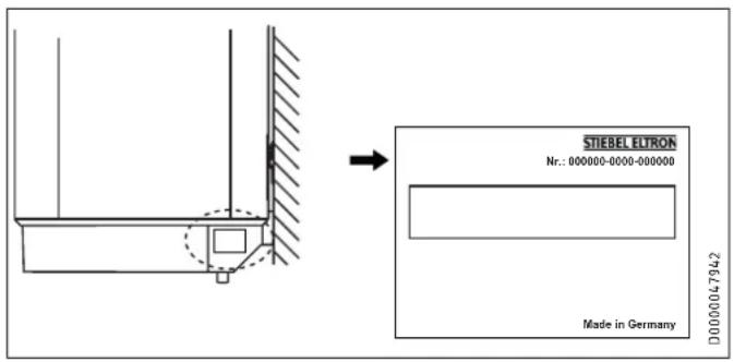
If you cannot remedy the fault, notify your qualified contractor. To facilitate and speed up your enquiry, please provide the serial number from the type plate (000000-0000-000000):
INSTALLATION
7. Safety
Only a qualified contractor should carry out installation, commissioning, maintenance and repair of the appliance.
7.1 General safety instructions
We guarantee trouble-free function and operational reliability only if original accessories and spare parts intended for the appliance are used.
7.2 Instructions, standards and regulations

Note
Observe all applicable national and regional regulations and instructions.
8. Appliance description
8.1 Standard delivery
The following are delivered with the appliance:
- Wall mounting bracket (2 pce for appliances with 120 l and 150 l nominal capacity)
- Spacers 5 mm (2 pce at the top / 2 pce at the bottom; for appliances with 120 l and 150 l, 4 pce at the top / 4 pce at the bottom)
Caps (2 pce)
Installation template
8.2 Accessories
Required accessories
Various safety assemblies are available for sealed unvented (pressure-tested) operation, depending on the static pressure. These type-tested safety assemblies protect the appliance against impermissible excess pressure.
Further accessories
Taps are available as accessories for open vented operation.
9. Preparations
9.1 Installation site
The appliance is designed for installation on a solid wall. Ensure the wall offers adequate load bearing capacity.
Always install the appliance vertically in a room free from the risk of frost and near the draw-off point.
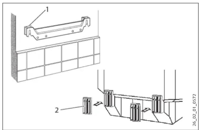
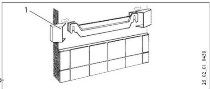
9.2 Fitting the wall mounting bracket
- You can use the installation template to transfer the dimensions to the wall.
- Drill the holes and secure the wall mounting bracket with screws and rawl plugs. Select fixing materials in accordance with the wall construction/condition.
You can compensate for unevenness in the wall with the spacers provided.
Appliances with a nominal capacity of 120 l or 150 l require 2 wall mounting brackets.
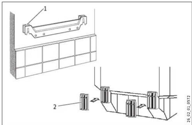
1 Upper spacer
2 Lower spacer
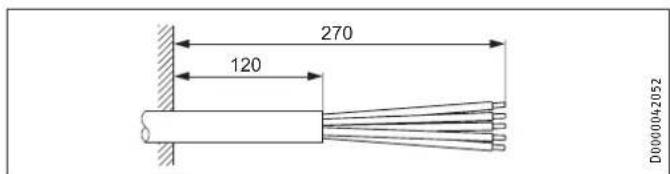
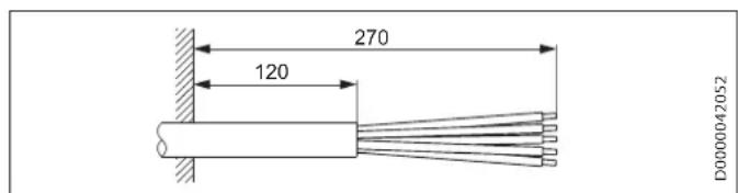
9.3 Preparing the connecting cables
10. Installation
10.1 Water connection

Material losses
Carry out all water connection and installation work in accordance with regulations.
For sealed unvented (pressurised) operation, operate the appliance only with pressure-tested taps. For open vented (non-pressurised) operation, use non-pressurised taps. Connect the hydraulic connections with flat gaskets.
10.1.1 Permissible materials

Material losses
When using plastic pipework, observe the manufacturer's data and the chapter "Specification / Fault conditions". The temperature setting can be limited by the qualified contractor (see chapter "Settings / Limiting the temperature selection").
Cold water line
Galvanised steel, stainless steel, copper and plastic are approved materials.
A safety valve is required.
DHW line
Stainless steel, copper and plastic pipework are approved materials.
10.1.2 Sealed unvented (pressure-tested) for supplying several draw-off points
The max. permissible pressure must not be exceeded (see chapter "Specification / Data table" and cylinder specification).
Install a type-tested safety valve in the cold water supply line. Please note that, depending on the static pressure, you may also need a pressure reducing valve.
Size the drain so that water can drain off unimpeded when the safety valve is fully opened.
Fit the discharge pipe of the safety valve with a constant downward slope and in a room free from the risk of frost.
The safety valve discharge aperture must remain open to the atmosphere.
10.1.3 Open (non-pressurised) for supplying one draw-off point

Note
Never shut off the outlet and pivoting spout.
Do not use an aerator.
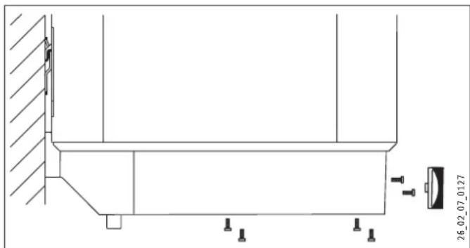
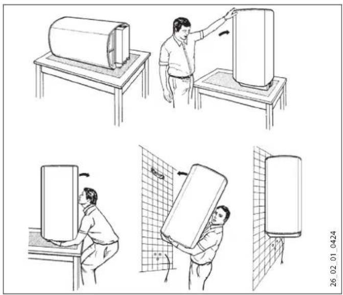
10.2 Appliance installation
Appliances with a nominal capacity of 120 l or 150 l require 2 people for installation.
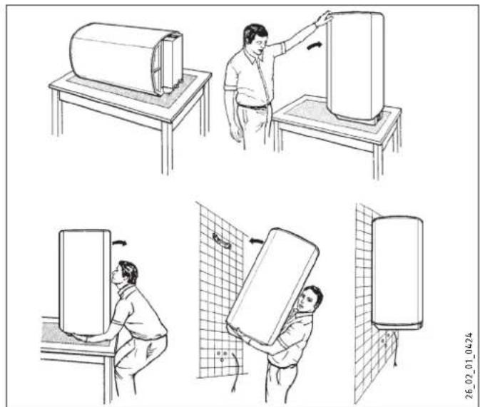
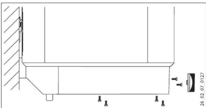
1 Cap
Fit the caps.
10.3 Power supply

WARNING Electrocution
Carry out all electrical connection and installation work in accordance with relevant regulations.
Before any work on the appliance, disconnect all poles from the power supply.

WARNING Electrocution
The connection to the power supply is only permissible as a permanent connection in conjunction with the removable cable grommet. Ensure the appliance can be separated from the power supply by an isolator that disconnects all poles with at least 3mm contact separation.

WARNING Electrocution
Ensure that the appliance is earthed.

Material losses
Install a residual current device (RCD).

Material losses
Observe the type plate. The specified voltage must match the mains voltage.
Pull off the temperature selector.
Undo the screws.
Remove the lower cap.
Pull the cable grommet out downwards while pressing on the locking hooks.
- Push the cable grommet over the connecting cable and snap the cable grommet back in place.
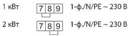
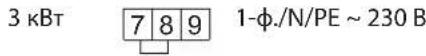
Connect the required load in accordance with the wiring diagrams (see chapter "Specification / Wiring diagrams and terminals").
Fit the lower cap.
Insert the screws.
Push on the temperature selector.
- Tick the selected connected load and voltage on the type plate with a ballpoint pen.
Sealed unvented (pressure-tested) operation
Connect the safety assembly to the appliance by screwing the pipes onto the appliance.
Open vented (non-pressurised) operation
Connect the appliance to the tap.
11. Commissioning
11.1 Commissioning
- Open a draw-off point until the appliance has filled up and the pipework is free of air.
Adjust the flow rate. For this, observe the maximum permissible flow rate with a fully opened tap (see chapter "Specification / Data table").
Sealed unvented (pressure-tested) operation: If necessary reduce the flow rate at the butterfly valve of the safety assembly.
Turn the temperature selector to maximum.
Switch the mains power ON.
Check the function of the appliance. Ensure that the thermostat switches off.
Sealed unvented (pressure-tested) operation: Check the function of the safety assembly.
11.1.1 Appliance handover
Explain the function of the appliance and safety assembly to users and familiarise them with their operation.
Make users aware of potential dangers, especially the risk of scalding.
Hand over these instructions.
11.2 Recommissioning
See chapter "Commissioning".
12. Settings
Limiting the temperature selection
You can adjust the temperature selection limit beneath the temperature selector.
Set the temperature selector to "cold" and isolate the appliance from the power supply.
Remove the temperature selector.
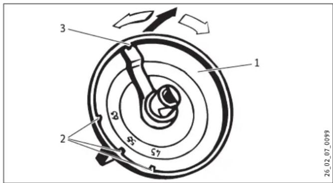
1 Temperature selector
2 Temperature selection limit at 45^, 55^, 65^
3 Factory setting 85^
Adjust the temperature selection limit.
Replace the temperature selector.
13. Shutting down
- Disconnect the appliance from the mains at the MCB/fuse in the fuse box.
- Drain the appliance (see chapter "Maintenance / Draining the appliance").
14. Troubleshooting

Note
At temperatures below -15^ the high limit safety cut-out may respond. The appliance may be subjected to these temperatures during storage or transport.
| Fault Cause | Remedy | |
| The water does not heat up. | The high limit safety cut-out has responded because the controller is faulty. | Remedy the cause of the fault. Replace the controller-limited com-bination. |
| The high limit safety cut-out has responded because the temperature has fallen below -15 °C. | Press the reset button (see diagram). | |
| The flanged immersion heater is faulty. | Replace the flanged im-mension heater. | |
| The safety valve drips when heating is switched off. | The valve seat is contam-inated. | Clean the valve seat. |
| SERVICE ANODE indicator illuminates. | The signal anode has been consumed. | Replace the signal anode. |
Reset key, high limit safety cut-out
The reset button is located behind the temperature selector.
Pull off the temperature selector.
1 Reset key, high limit safety cut-out
2 Controller/limiter combination
15. Maintenance

WARNING Electrocution
Carry out all electrical connection and installation work in accordance with relevant regulations.
Before any work on the appliance, disconnect all poles of the appliance from the power supply.
For some maintenance work, the lower cap must be removed.
If you need to drain the appliance, observe chapter "Draining the appliance".
Note the insertion depths of the controller-limiter combination (see chapter "Specification / Dimensions and connections").
15.1 Checking the safety valve
Check the safety valve regularly.
15.2 Draining the appliance

WARNING Burns
Hot water may escape during the draining process.
If is necessary to drain the cylinder for maintenance or to protect the whole installation from frost, proceed as follows:
Close the shut-off valve in the cold water feed line.
Open the hot water taps on all draw-off points.
1 Drain valve with hose connection G 3/4
Undo the cap of the "drain" connection.
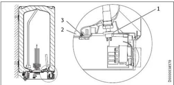
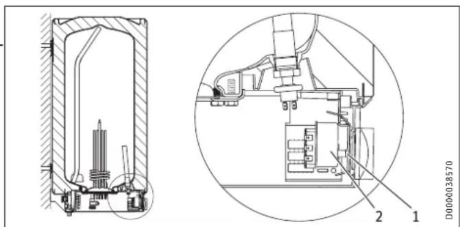
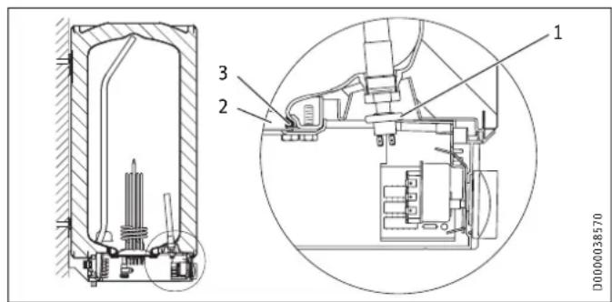
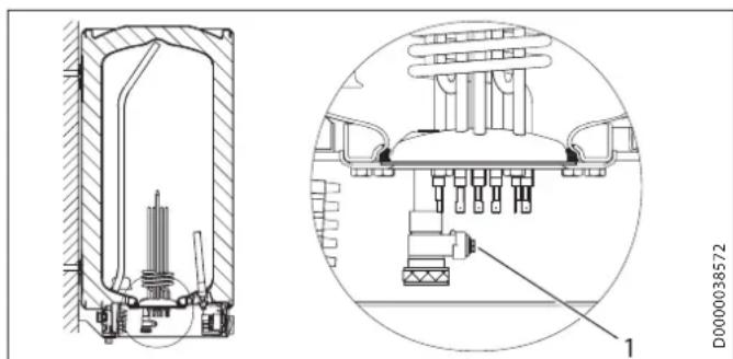
1 Pressure switch for signal anode
2 Flange plate
3 Seal ring
- When replacing the anode, take great care to fit the pressure switch on tightly.
Torque: 1^+0.5 Nm (tighten by hand)
15.4 Descaling
- Open vented operating mode: If you are using a mixer tap with a hand shower, regular descending will be necessary.
Only descale the flange after disassembly and never treat the cylinder surface or signal anode with descending agents.
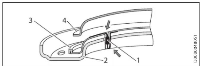
15.5 Anti-corrosion protection
When carrying out service work, ensure that the anti-corrosion protection on the insulating plate is not damaged or removed. Reinsert the anti-corrosion protection correctly after replacement.
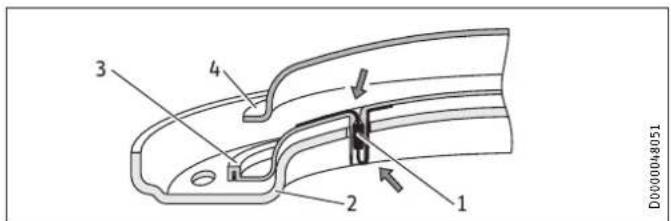
1 Anti-corrosion protection (390 Ω)
2 Pressure plate
3 Insulating plate
4 Flanged immersion heater
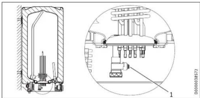
15.3 Checking / replacing the signal anode
If the SERVICE ANODE indicator illuminates, check the signal anode and replace if necessary.
SH 30 S (M 8)
Removed the flanged immersion heater to replace the signal anode.
SH 50 - 150 S (G 3 / 4
You can replace the anode without removing the flanged immersion heater.
16. Specification
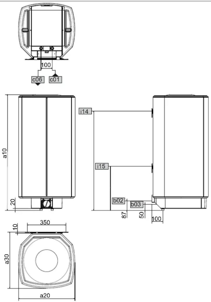
16.1 Dimensions and connections
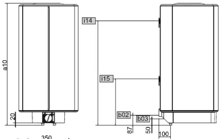
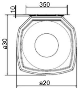
D0000024799
| SH 30 S SH 50 S SH 80 S SH 100 | SH 120 S | SH 150 S | ||||||||
| a10 | Appliance | Height | mm | 770 | 740 | 1050 | 1050 | 1210 | 1445 | |
| a20 | Appliance | Width | mm | 410 | 510 | 510 | 510 | 510 | 510 | |
| a30 | Appliance | Depth | mm | 420 | 510 | 510 | 510 | 510 | 510 | |
| b02 | Entry electrical cables I | PG 21 | PG 21 | PG 21 | PG 21 | PG 21 | PG 21 | |||
| b03 | Entry electrical cables II | |||||||||
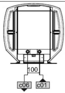
| c01 | Cold water inlet | Male thread | G 1/2 A | G 1/2 A | G 1/2 A | G 1/2 A | G 1/2 A | G 1/2 A | ||
| c06 | DHW outlet | Male thread | G 1/2 A | G 1/2 A | G 1/2 A | G 1/2 A | G 1/2 A | G 1/2 A | ||
| i14 | Wall mounting bracket I | Height | mm | 700 | 600 | 900 | 900 | 900 | 1100 | |
| Max. Ø fixing screw | mm | 12 | 12 | 12 | 12 | 12 | 12 | |||
| i15 | Wall mounting bracket II | Height | mm | 300 | 300 | |||||
| Max. Ø fixing screw | mm | 12 | 12 | |||||||

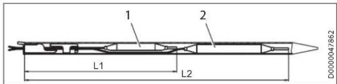
Controller-limiter combination immersion depths
1 Limiter sensor
2 Controller sensor
| SH30 S | SH50 S | SH80 S | SH100 S | SH120 S | SH150 S | ||
| L1 | Immersion depth | mm | 260 | 260 | 240 | 240 | 260 |
| L2 | Immersion depth | mm | 380 | 380 | 350 | 350 | 380 |
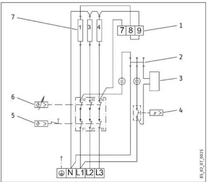
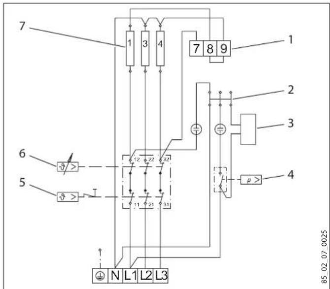
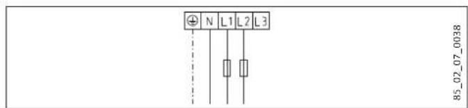
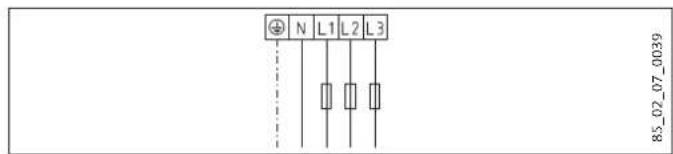
16.2 Wiring diagrams and terminals
1 Terminal for output changeover
2 Plug-in distributor for N conductor
3 Heat content indicator
4 Pressure switch for signal anode
5 High limit safety cut-out
6 Temperature controller
7 Heating element, 2kW 230V each
16.3 Heat-up diagram
The heat-up time depends on the cylinder capacity, cold water inlet temperature and heating output.
Diagram with 15^ cold water temperature:
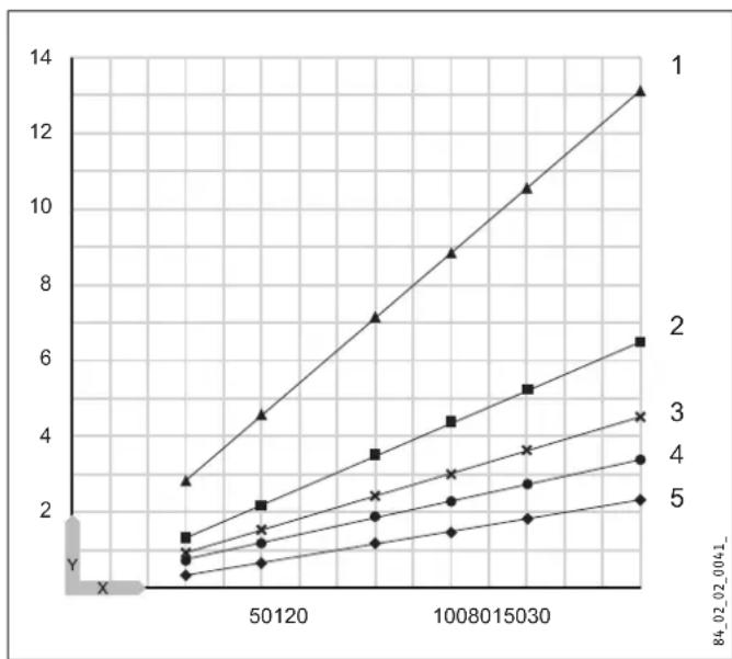
Set temperature setting 82^
X Nominal capacity [1]
Y Duration [h]
1 1 kW
22kW
3 3 kW
4 4 kW
56kW
16.4 Fault conditions
In the event of a fault, temperatures of up to 95^ at 0.6MPa can occur.
16.5 Details on energy consumption
Product datasheet: Conventional water heaters to regulation (EU) no. 812/2013 and 814/2013
| SH 30 S | SH 50 S | SH 80 S | SH 100 S | SH 120 S | SH 150 S | |
| 073047 | 073048 | 073049 | 073050 | 073051 | 073052 | |
| Manufacturer | STIEBEL ELTRON | STIEBEL ELTRON | STIEBEL ELTRON | STIEBEL ELTRON | STIEBEL ELTRON | STIEBEL ELTRON |
| Load profile | S | M | M | L | L | XL |
| Energy efficiency class | B | C | C | C | C | C |
| Energy conversion efficiency | % | 36 | 38 | 37 | 38 | 39 |
| Annual power consumption | kWh | 518 | 1349 | 1381 | 2666 | 2705 |
| Default temperature setting | °C | 60 | 60 | 60 | 60 | 60 |
| Sound power level | dB(A) | 15 | 15 | 15 | 15 | 15 |
| Option for exclusive operation during off-peak periods | - | - | - | - | - | - |
| Smart function | - | - | - | - | - | - |
| Daily power consumption | kWh | 2.437 | 6.233 | 6.419 | 12.288 | 12.516 |
| Amount of mixed water 40 °C | l | 50 | 80 | 122 | 133 | 182 |
16.6 Data table
| SH 30 S SH 50 S SH 80 S SH 100 S | SH 120 S SH 150 S | |||||
| 073047 | 073048 | 073049 | 073050 | 073051 | ||
| Hydraulic data | ||||||
| Nominal capacity | I | 30 | 50 | 80 | 100 | 120 |
| Amount of mixed water 40 °C (15 °C/65 °C) | I | 59 | 97 | 159 | 198 | 235 |
| Electrical data | ||||||
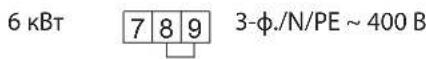
| Connected load ~ 230 V | kW | 1-4 | 1-4 | 1-4 | 1-4 | 1-4 |
| Connected load ~ 400 V | kW | 3-6 | 3-6 | 3-6 | 3-6 | 3-6 |
| Phases | 1/N/PE, 2/N/PE, 3/N/PE | 1/N/PE, 2/N/PE, 3/N/PE | 1/N/PE, 2/N/PE, 3/N/PE | 1/N/PE, 2/N/PE, 3/N/PE | 1/N/PE, 2/N/PE, 3/N/PE | |
| Rated voltage | V | 230/400 | 230/400 | 230/400 | 230/400 | 230/400 |
| Frequency | Hz | 50 | 50 | 50 | 50 | 50 |
| Single circuit operating mode | X | X | X | X | X | |
| Application limits | ||||||
| Temperature setting range | °C | 35-82 | 35-82 | 35-82 | 35-82 | 35-82 |
| Max. permissible pressure | MPa | 0.6 | 0.6 | 0.6 | 0.6 | 0.6 |
| Test pressure | MPa | 0.78 | 0.78 | 0.78 | 0.78 | 0.78 |
| Max. permissible temperature | °C | 95 | 95 | 95 | 95 | 95 |
| Max. flow rate | l/min | 18 | 18 | 18 | 18 | 18 |
| Min. water inlet pressure | MPa | 0.1 | 0.1 | 0.1 | 0.1 | 0.1 |
| Max. water inlet pressure | MPa | 0.6 | 0.6 | 0.6 | 0.6 | 0.6 |
| Min./max. conductivity, drinking water | μS/cm | 100-1500 | 100-1500 | 100-1500 | 100-1500 | 100-1500 |
| Energy data | ||||||
| Standby energy consumption/24 h at 65 °C | kWh | 0.46 | 0.54 | 0.67 | 0.86 | 0.99 |
| Energy efficiency category | B | C | C | C | C | |
| Versions | ||||||
| IP rating | IP25 | IP25 | IP25 | IP25 | IP25 | |
| Sealed unvented type | X | X | X | X | X | |
| Open vented type | X | X | X | X | X | |
| Colour | White | White | White | White | White | |
| Dimensions | ||||||
| Height | mm | 770 | 740 | 1050 | 1050 | 1210 |
| Width | mm | 410 | 510 | 510 | 510 | 510 |
| Depth | mm | 420 | 510 | 510 | 510 | 510 |
| Weights | ||||||
| Weight, full | kg | 53 | 78 | 118 | 140 | 165 |
| Weight, empty | kg | 23.1 | 28 | 38 | 40.8 | 45.5 |
Guarantee
The guarantee conditions of our German companies do not apply to appliances acquired outside of Germany. In countries where our subsidiaries sell our products a guarantee can only be issued by those subsidiaries. Such guarantee is only granted if the subsidiary has issued its own terms of guarantee. No other guarantee will be granted.
We shall not provide any guarantee for appliances acquired in countries where we have no subsidiary to sell our products. This will not affect warranties issued by any importers.
Environment and recycling
- Dispose of the appliances and materials after use in accordance with national regulations.

If a crossed-out waste bin is pictured on the appliance, take the appliance to your local waste and recycling centre or nearest retail take-back point for reuse and recycling.
This document is made of recyclable paper.
- Dispose of the document at the end of the appliance's life cycle in accordance with national regulations.
REMARQUESPARTICULIERES
UTILISATION
m = 311
13/14
13/14
m = 311
WAARSCHUWING verbranding
WAARSCHUWING verbranding
SH 50 - 150 S (G 3 / 4
U kurz de anode verrangen zonder de verwarmingsflens te demonteren.
X Nominate inhoud [I]
Y Duur [h]
1 1 kW
2 2 kW
3.3kW
4.4kW
56kW
15.4 Storingssituations
1.3 EdnHnCbI n3MepeHnA

Yka3aHne
Ecn He yka3aHO uHoe, Bce pa3MepbI npNBedeHbI B MnnnMeTpax.
2. TexHnka 6e3OnacHOCTN
2.1 NcnoJb3ObaHHe no Ha3HaueHnIO
Pnp6op npedha3nueH nla HarpBa BODonpoBOnHO Bobl. Pnp6op MoKeT o6cnyKuBaTb OHy, a npn EKnpyaTuN B 3aKpbITOM (HaOpHOM) pexkme - HeckoIbKO ToeK OT6opa.
-Приборпразнаначehдя 6ытOBОги NCПОьБЗВАн.Дя ero 6e3ОпалснохогообслУЖИВAHЯ NOЛБСОВATEH He Tpe6уETca npoxOДТь nHCTpyKТж.Bo3MOxHNo NCПОьБЗВАне рпбор He TOLьКВ 6bIty, Ho N, HApPIMep, Ha ppeNpRnTnxM Manoro 6u3HeCa пи уCNOBи CO6JIQUDEHЯ Tex Jxe yCNOBи AkCnIy- ataци.
HIO6oe HHOe Hn He yka3aHHoe B HactoIeM pyKOBODCTBe NCNOb3OBAHHe DaHHoro YcTPOJCTBa CHTaETcN CNOb3OBAHHe Me No Ha3HaueHIno. NcNOb3OBAHHe Me No Ha3HaueHIno CHTaETcTaTke NcNOb3OBAHne np6opAp nHaRpeBa
IIO6bIX dpyrnx KxuKoCTe KpOme BObl, a TaKke HarpeB BObl Cdo6abHeHem XmMknAaHnPumep, paccola.
NcNoIb3OBAHne NO Ha3HaueHHIO NoIpa3yMeBaET TaKke Co6JIIOeHHe Tpe6oBaHn HAcTOrIeRo pyKOBOCTBa, a TaKkepyKOBOCTB K IcNoJIb3yEmbIM PpHaJNeXHOCTM.
2.2 06uye yka3aHnno TeXnKe 6e3onacHOCTn

IPENyIPEKDEHNE oxor
Bo Bpemra pa60bI apMaTpaN npedeoxpAHnteNBHARpynna MoryT HarpeBaTbcn DO TemnepaTypb Cbbiue 60°C.
Pn TemnepaType BOBbl Ha BbIXOe Bblwe 43 ^ C cyueCTByET ONaCHOCTb OBapNBAHNA.

PENEUYIPEXJEHNE TpaBMa
IeTAM CTAPWE 3 ne, a TAKKHe NnUaM c OrpaHnueHHbIMn fN3nuecknM, ceHCOPHBIMn UymCTBENHbIMn CnOC6HOCTaMn, He IMeIOUIM ONbITaN He BnAdeIOUIm INoOpMaunE o np6ope, pa3peuheNOcNoB3OBaTB np6Op TObKO nOg npncMOTpOMdpyrnx IINu nnnoocne COOTBeTCTByUoero nHCTpykTaKa O npabunax 6e3OnacHOrO NOb3OBaHm N noTeHuaNbHO nnacHOCTN B cnYae HecO6NIOJeHnERNTx npabUN. DeTAM B BO3pacte ot 3 do 8 net pa3pewaaetc NOb3OBaTbCA TObKO cmecntenEM, NOKIIoueHHBM K np6opy. He donyckatb WanoCTeIeTeN C np6opom. DETu Moryr BBInONHrT bNCtkynp6opaN Te BnDbI TexHnueCKoro 06CnyKBaHnR, KOtOpbie O6bHuO npOn3BOaTcra NOb3OBaTeMe, TOlbKO NO pncMOrPOM B3POcNbIX.

MaterpaHbHbIyuep6
BoonpoBOD n npdeoxpaHnteNbHa rpynnn daJxHb6bTb 3aunueHb ot 3aMeP3aHn noIb3ObaTeNeM.

Yka3aHnE
Pn6op 3akpbitoro Tuna: np6op HaxoHCTnoDabJeHem. Bo BpemHarpeBa BOa BCneCTBue TeNIOBORO pacuHpeHn KaetaT n peoxpaHHTeJbHorO kanaHa.
EcnnoOKOHAHnHarpeBa BOa no-npexHemy
IoKanbBaET, Heo6xOdmo COo6uNTb 06 3TOM CneunnaNCTy.
Pn6op OTKpbIToR Tnna: npn KaXdOM HArpeBaHn paunpOaAraB Oda KaNaET B MeCTe CnBa.
2.3 3HaK TexHnueckOro KOHTpOJIa
Cm.3aOoDcky Ta6nUky Ha np6ope.
Ebp3Mckoe COOTBETCTBNE
AeDnHbI npn6Op COoTBcTByET Tpe6OBaHNm 6e3OnacHOCTn TexHnuecknx pernameHTOB EbpaaNCKORO 3KohOMuYeCKORo Co03a TP TC 004/2011, TP TC 020/2011 n npouen cooTBcTByIOUne npoeDpybl NpOdBepKdEHHa COoTBcTBN. CepTNΦHKAT COoTBcTBN NTOC R U C-DE.AR46.B84155, cPOK dEiCTBnC 21.02.2018 r. no 20.02.2023 r. Opran no cepTNΦKaUNIg PO-CTECT-MockBa" AO "PernoHaJIbHbI opran no cepTNΦKaUNIg TeCTnipoBaHNUO".
3.Описане устpoиства
Pnp6op npedctabnaret c06o3neKtpnueeckn HarpBaTeIb BODonpoBDOHO B0dbicpeKIMOM cTaHapTHorO HarpBeA. TemnepaTpya 3adaetcpeyraTOpom TemnepaTpyb. ABtomaTueckn HarpeB do HyxhoT TemnepaTpyb npOn3BOUntcB 3aBncmocn ot 3eKtpoCha6xeHnHa dncnnee oTo6paxaETcdoCTynhbo O6bem ropaye BObl.
MooKET 3KcNJIyATnIPOBaTbCk Ka npu6Op OTkpBtORO (6e3Ha-nOPHoro), TaK n 3AkpytORo (HanopHoro) Tnna.
CtaIbHOB BHyTpEHHN 6aK IMeET CneuaJIbHoe 3MaIeBoe NOKpbITNE «anticor» n OCHaueH CNrHaJIbHbIM aHOJOM. AHOc c HnDnKaTOpOM n3Hoca o6ecneuBaet 3aunTy BHyTpEHHero 06bema pe3epByapa ot KoppoHN.
3.1 PexkM 3aunTbI OT 3amep3aHnA
Pn6bOp 3aunuH eOH 3amep3aHnRA TAKKe npu yctahOBke peryIaTopa TemnepaTpby Ha XoJIOHO, HO nIra 3TOr OH dONKeH 6bIb NODKIIouen K CETn 3neKtponitAHn. Pn6bOp CBOBpeMeHHO BkIIOUaETcN HArpeBaET BOy. Pn6bOp He 3aunuaeTrpy6bI BOOnpOBOda N PpeDOxpaHTeNbHbIKOMNNEKT OT 3amep3aHnR.
4. Hactpoikn
PerynipobkA TemnepaTpybI npOn3BOuNTc6ecctyneHauTo.
1 CnHnBna JAMNa HnDnKaun pa6oeryo pexmna
B KOMPJIeK T NOCTABK IN Pn6opa BxOJaT:
HacteHHaMOHTaXHaIpaHaKa(2Wt.ДЯ np6OpOB HOMHaHbHO BmecTmOcTbIO 120 n 150n)
Pacnopkn 5 MM (2 wt. Bbepxy / 2 wt. Bn3y; Дя пиборов 120 n 150 n 4 wt. Bbepxy / 4 wt. Bn3y)
- 3aunthbte konnaKn (2 wt.)
- Ⅲa6noH dIy MOHTaxa
8.2 ПинадлжноTN
Heo6xoDnmbie npuHaNexKHOCTn
Дя пиборов 3akpbitoro (hanophoro) Tnna npedlaarotcra pa3niuHbIe npedoxpaHnteJbHbIe rpynnbI B 3aBucmocTo OT ctaTueckoro daBneHn. PpeoxpaHnteJbHbIe y3nbI cepTIN- fHnnpOBaHHoKohCTpykUnn 3aunuAOT np6Op OT HeDonyCTMbIX npebblweHn daBneHn.
DononHnteIbHbIe npHaadJeXHOCTu
ApaMaTypaIJI6e3HaOpHoi 3KcNpyatauIN npi6OpOB npednaaraetca KaK DOnONHHTenbHbe pInHaDnExKHOCTN.
IodrotobntbHbIe MeponpnyTnA
8.3 MecTo MOHTaxa
Pnp6op npedHa3HaueHdI JxecTKoro KpePnHeHa CTHe. CTeHa DOnJXHa 6bITb paccuHTaHa Ha COOTBeTcByIOUyIO Ha- rpy3Ky.
YcTaHaBnBaTb np6Op TOnbKO BepTKKaIbHO, B He3aMeP3aIO- 1eM NomeeHnn PraDM C KpaHOM.
8.4 YcTaHOBKa HAcTeHHoM OHTaXHOH NlaHKn
Дяпегерosa pa3меров Ha CTeHy moXHO nCNoIb3OBAtB 7a6noH dЯ мотэж.
PpocBepnntb OTBepCTn n 3akpeHnTb HactEHHyo MoTHaKHyIO pHaHKy C NMOOuB IO uypynOB n IIO6eJe. KpeNexKhbl MaTePiAn CneDyET Bbl6HpTaB c yyeToM npouHOCTn CTHebl.
HepOBHOCTN CTeHbI KOMPHeHCpyIOTcNoDxOJaUIMPaCnpOPKaMn.
Ipynp6opOB HOMHaJIbHOB BMECTmOcTbIO 120 n 150 n Tpe6yOTc 2 HAcTeHHbIE MOHTaXHbIe pHaHKn.
1 BCTaBka BBepxy
2 BCTABKa BHN3y
8.5 Nodrotobka Ka6eJEAneKtponTuHa
9. MoHTaJx
9.1 PoiKJIoueHne BOdi

MaTePnAJIbHbI yUeep6 Bce pa6OtI NO NOKJIIOHeHIO BOdI IN MOHTaXy npi- 6opAp Heo6xOJIMO ppon3BOJNTb B COOTBeTCTBUN C nHCTpykCne.
PnE3KpNpyataunnp60paB3akpbTOM Bne(HanopHbTUN) Heo6xoJmo NcnojB3ObaTb HAnOpHyIO apMaTyPy. PnE3KpNpyataunnp60paBOTkpBtOM Bne(6e3HaOpHbTUN) Heo6xoJmo NcnojB3ObaTb 6e3HaOpHyIO apMaTyPy. FnpabmHeCKne JInHH CnepdyET npncoeuHrTb Cnlockm yIIOHTHeHem
9.1.1 MaTePnAJIbI, donyueHhbIe K npUmHeHnIO

MATEPNAJIbHbI yuep6
Pn nCNoB3OBaHN Tpy6 n3 PnactNka HxKHO CneDoBAtyka3AHm Ppon3BOJnteY I rnaBbl 1TexHueCKne XapakTePncTuk / Bo3MOXhble HeNCnpaBHOCTN). OrpaHnueHHe TempepTaTpbi HarpeBa MoKeT BbINOnHHTcneuaHnCT (cm. rnaBy AcToKn/HAcToKnOraHnTuTeA TempepTaBl).
BodonpoBoDnaHnnnXoNoHOBdBi
B KaueCTBe MaTePnaIob pa3peWeHo nCNoIb3ObaT bropaEOuHnKOBaHHyIO CTaJIb, HepKaBaEIOU cyIO CTaJIb, MeDb I nPaCTIK.
Heo6xoDnma yctaHOBka npedeoxpaHnteBhoro knaHa.
BodonpoBODHnIHHnropaue BOdbI
B KaueCTBe MaTePnAna Ia Tpy6 pa3peSeHo IcNoIb3OBaTb HepXabeIOUyIO CTaIb, MeB n INaCTNK.
9.1.2 3akpbitoro Tuna (Hanophbl) dna cha6xehna HeckolbKnx ToeK OT6opa
HeneB3 npebbiwabMakc. donyctmoe daBneHne (cm. rnaBy "Texnueckne xapaKtepncTkn / Ta6nua napameTpOB" n "Texnueckne xapaKtepncTkn peepbyapa").
YctaHOBnTb npedoxpAHnteHbHKnanaH ceptnoHPO BAHHO KOHCTpyKuIN B Tpy60npOBoN NOaun XOIOHO BObl. B 3abNCIMOCTH O CTaTNueCKORO daBHeN MOKET DOONHTeHbNOOTpe6OBaTcR yCTaHOBa peyKUHOH Horo KnaHa.
Pa3mepbIO TBOHON Tpy6bI NOO6paTb TAKIM O6pa3OM, 7TO6bI BOa npN PNOHOCTbIO OTKpbITOM ppeOxpaHNTeH-HOM KnaHaHE BbTEkana 6ecnpenrTCTBEHHO.
PpOdyBOHyIO HnHIO npEdoXpaHnteBHO y3a MoHTIPOBaTb B He3aMepe3aIOUeEM NOMEueHIN, C NOCToHHbIM YKJOHOM BHN3.
POnyBOuHoe OTBepCTne npedoxpaHHTeNbHO RJIanaHa DOJXHO OCTaBaTbCRAOTKpbITbIM B aTMOCepy.
9.1.3 OTKpbItoro Tuna (6e3HaOpHbI) dna cHa6xehnOdHOJ TOUKn OT6opa

Yka3aHne
HeIb3npeKpbIbATb CINB n 6IOknpoBaTb NOBOPOTHbI pbUar apMaTyprbl.
HeIb3a nCnONb3OBaTb peryIaTOpbI cTpyu nn a3paTOpbl.
9.2 MoNTax npu6opa
Дя мontак npиборов HOMHаьн Вмстmoctь 120 n 150 n tpe6yotc 2 chenobeka.
1 3aunTHa KpbIwka
YcTaHOBnTb 3aunTHbIe KOJNaUKn.
9.3 3neKtpnuecko noKnIOUoyHe

IPEyIPEXJEHNE npaKeHne 3JekTpuecknM TOKOM
Bce pa60tI no 3neKtpnueckomy nOdkJIoueHIO mOHTaKy Heo6xOIMMO pON3BOJNTb B COOTBeTCTBUN C INHCTpykCnei.
PnIIO6bIX pa60tax Heo6xOJIMO NOHoe OTKJIueHne np6opa oT cTeN.

PPEyPPEKDEHNE npaKeHne 3JekTpuecknM TOKOM
IopKnIOUeHHe K 3JeKTPoCeTn DOyCTmO ToJbKO B Hepa3bEmHom NcONJIHeHnn, Co CbeMHOn Ka6eJIbHOB BtynKo. Pnp6Op DOnKeH OTcoEINrTbcra O T cTeu C pactBOPom BCex KOHTaKTob He MeHee 3 MM Ha Bcex noJIocax.

PPEyPPEKDEHNE npaKeHne 3Jektpueckm TOKOM
PpOBepntb noDKnIoueHne np6opa K 3aunTHOMy npoBody.

MaTePnAJIbHbIy uIeep6
YCTaHOBt b yCTPOCTBO 3aIHTb OT TOKa yTeuKn (Y3O).

MaTePnAJIbHbIy uIeep6
CnejyeTco6nIaTaBdaHHbIeHa3aBOcKoTa6nUKe.
Hanpajxehne cetn donjxho coBnaDaTb cyka3aHHbIM Ha Ta6JnuKe.
Chatb pyky perynltopa Temnepaypbl.
OTBnHTntb BNHTbl.
CHaTb HxHxHIO KpbIiKy.
BbIaunTb Ka6eHbHbB BBOB HnPaBHeHN KHN3y, npN TOM ydepKINBaT bNKCaTOP HaKaTbIM.
Pponyctntb nitaioi Ka6eIb uepe3 Ka6eIbHbI BBOID HOBa 3aΦIKCnpoBaTb erO.
IOnkInuHb HxHyIO MoUHOCTb B COOTBcTbN CO CxEAMn coeHHeHn (cm. rnaBy *TexHueckne xapaKtepnrukn / 3neKtpueckne cxembl n coeHHeHnra).
YcTaHOBnTb HxKHiO KpbIiKy npu6opa.
3aBnHTnBnHTbl.
YcTaHOBnTb pyuKpyeYJrToPa TeMnepaTpybl.
ⅡapuKOBpyKoOTMeNTbHa3aBockoTa6nueKe
KpeCTIKOM BbI6paHHyIO IJIa NODKIIOueHnRA MOUHOCTb HAnpJKeHne.
Pn6op 3akpbitoro (HanopHoro) Tuna
CoeunHntb npedoxpaHnteBHy bY3en c np6opom, nCnOJb3y dI KpENHeH Tpy6 pe3b6OBoe coeHNHeHne.
Pn6op oTKpbIToro (6e3HanopHoro) Tuna
PnBnHTb apMaTpy K np60py.
Pn onpeJeHbIx pa6oTax no Texo6cnyxuBaHnHO Heo6xoDnMo CHMaTb HxKHiO KpbIiKy.
Ecn Heo6xOJIMO OOnopKHNb npn6Op, Heo6xOJIMO cneioBaTb yka3aHnM rnaBbl «OnopKHeHne npn6opa>.
CneObaTb yka3aHbIM 3HaueHnM rny6uHbI nOrpyKeHnKOM- 6uHnpOBaHHoro yCTpoiCTBa «peryIaTOp-orpaHnUHTeIb» (CM. rnaBy «TexHnueckne xapaKTePncTnKn / Pa3mpeBn coeHnHeHnA»).
14.1 Поверка пpeохсаньног КлanaHa
PerynepHO BbINHrTb npOBepky npedoxpaHntbHoroklananaHa.
14.2 OnopoxKHeHne np6opa

IPEUYIPEKDEHNE oxor
PnOnopOxHeHn Pnp6opa n3 Hero MoKet BbITEKaTb ropya BOa.
Ecni Ia TeXo6CnyKuBaHnI nn 3aunTbI BceY uCTaHOBKn OT 3amep3aHnHyxHo npou3BeCTn CInB BOdbI,TO Heo6xoJIMO BblONHHTcNeDyUOJe WArI:
3aKpbIb 3aOpHbI BcHTnIb B Tpy6oNpOBoe nOaU XoJIoHOB BObl.
OTkpblb KpaHbI ropueyB BObl BO BCex Tockax OT6opa
1 CInBHOB BENTINb CO WTyepom Dnla UNaHra G 3/4
OTBepHyTb KpbIuKy co CnNBHoro naTp6Ka.
PpOBepntb, yTO6bl npTexHnueckOM o6cnykBaHN Ha n3OlnpyuOe naHeI N He 6bl NOBpeJdeH nn ydaJIe H aHTNKoppo3NoHHb pe3NCTOp. HAnEkaUIM O6pa3OM BOCCTaHOBNT 3aunTHoe NOKpbITne npOTNB Koppo3H NocNe 3aMeHbI.
1 AntKoppo3nOHbI pe3nCTop (390 OM)
2 PnKmHa naHeB
3I3oIpyuOa naHeB
4 Φlahec c harpeBaTeIbHbIM T3Hom
15. Texhnueckne xapaKTepeNCTnKN
15.1 Pa3mepbI n coeMHHeHnA
| SH 30 S SH 50 S SH 80 S SH 100 S SH 120 S SH 150 S | ||||||||
| a10 | Прибор | Высota | MM | 770 | 740 | 1050 | 1050 | 1210 |
| a20 | Прибор | ШирINA | MM | 410 | 510 | 510 | 510 | 510 |
| a30 | Прибор | Глбиha | MM | 420 | 510 | 510 | 510 | 510 |
| b02 | Ввдддддддддддддддддддддддддддддддддддддддддддддддддддддддддддддддддддддддддддддддддддддддддддддддддддд徳 | PG 21 | PG 21 | PG 21 | PG 21 | PG 21 | PG 21 | |
| b03 | Ввдддддддддддддддддддддддддддддддддддддддддддддддддддддддддддддддддддддддддддддддддддддддддддддддд徳 | |||||||
| c01 | Повдддддддддддддддддддддддддддддддддддддддддддддддддддддддддддддддддддддддддддддддддддддддддддддддддддد | Hаржная рezь6a | G 1/2 A | G 1/2 A | G 1/2 A | G 1/2 A | G 1/2 A | G 1/2 A |
| c06 | Быпск. Trуба رорочь вовы | Hаржная рezь6a | G 1/2 A | G 1/2 A | G 1/2 A | G 1/2 A | G 1/2 A | G 1/2 A |
| i14 | Планka дд д д дд дд d d d d d d d d d d d d d d d d d d d d d d d d d d d d d d d d d d d d d d d d d d d d d d d d d d d d d d d d d d d d d d d d d d d d d d d d d d d d d d d d d d d d d d d d d d d d d d d d d d d d | Высota | MM | 700 | 600 | 900 | 900 | 900 |
| Мakс. Диаметр крөного ВИNTа | MM | 12 | 12 | 12 | 12 | 12 | ||
| i15 | Насенья мontайная планka II | Высota | MM | 300 | ||||
| Мakс. Диаметр крөного ВИNTа | MM | 12 | ||||||
MOHTAK
TexHnueckne xapaKTepeNCTnKN
Kom6nHaacna(peryIaTOp-orpaHmUteNb》,rny6nHa norgyKeHn
1 DaTnK OpraHnUteIa
2ДатчкperynЯтopa
| SH | 30 S | 50 S | 80 S | 100 S | 120 S | 150 S | ||
| L1 | Глобина пору-жения | MM | 260 | 260 | 240 | 240 | 240 | 260 |
| L2 | Глобина пору-жения | MM | 380 | 380 | 350 | 350 | 350 | 380 |
15.2 3neKtpnueckn cXembl n coeHHeHna
1 Klemma nna nepekeKIOueHnro MOUHOCTN
2UTekehbu coeHHntb nHyeBOr npoBoa N
3 INHdkatop doctynHoro oBbema ropaye BOdb
4 THEBMaTnueckn BbIKNIOuTaTeNb dIra CnHrHaBHO r aHOda
5 PpeoXpaHnteBHybOrgaHnHTeB Temnepeatypbl
6 Perynatop TemnepaTpybI
7 HarpeBaTeBbHbIe 3neMeHTbI NO 2 KBT, 230 B
15.4 Bo3MOxHbIe HcnpaBHOCTn
Pn HeucnpaBHOCTu Tempepatya npu 0,6 MNa MoKeT NOBbI- WATbcra do 95^
15.5 XapaKTePncTnKN 3HeprnonTope6neHn
TexHnueckne xapaKTepeNCTNK n3dEJIa: CtaHdapTHbI BDOHOarpeBaTeJIb (B COOTBeTcTBUN c perJameHToM EC Ng 812/2013 | 814/2013)
| SH 30 S | SH 50 S | SH 80 S | SH 100 S | SH 120 S | SH 150 S | ||
| 073047 | 073048 | 073049 | 073050 | 073051 | 073052 | ||
| Пюизвodи龟ь | STIEBEL ELTRON | STIEBEL ELTRON | STIEBEL ELTRON | STIEBEL ELTRON | STIEBEL ELTRON | STIEBEL ELTRON | |
| Пюофиль Нагузkin | S | M | M | L | L | XL | |
| Клascьнисторддгпь | B | C | C | C | C | C | |
| Знергетшистеский КПД | % | 36 | 38 | 37 | 38 | 38 | 39 |
| Гововские по trade ленице щаclуатацinn Ickliочтелно | kWh | 518 | 1349 | 1381 | 2666 | 2705 | 4321 |
| Заданая на захode TemпераТура | °C | 60 | 60 | 60 | 60 | 60 | 60 |
| Уровень звековий мошоносту | ДБ(A) | 15 | 15 | 15 | 15 | 15 | 15 |
| Возможность леслиуатацinn Ickliочтелно | - | - | - | - | - | - | |
| В п��iodы НИЗКОн Hagузkin | - | - | - | - | - | - | |
| Фунkedя Smart | - | - | - | - | - | - | |
| Сточhoe по trade ленице щаclуатацinn Ickliочтелно | kWh | 2,437 | 6,233 | 6,419 | 12,288 | 12,516 | 19,859 |
| Оьем смешаанно Вобdi 40 °C | I | 50 | 80 | 122 | 133 | 182 | 229 |
129343, r. MockBa, Poccn
15.6 Ta6nua napametpoB
| SH 30 S SH 50 S SH 80 S SH 100 S SH 120 S SH 150 S | 073047 | 073048www.stiebel-eltron.ru073049www.stiebel-eltron.ru | 073050 | 073051 | 073052 | |
| Гиравлиескиххарakтериски | ||||||
| Hominahьая EMKOSTb | I | 30 | 50 | 80 | 100 | 120 |
| Оьем смешаимов Bodу 40 °C (15 °C / 65 °C) | I | 59 | 97 | 159 | 198 | 235 |
| Зл ekтуескиххарakтериски | ||||||
| Подknюаемая мошноctы ~ 230 B | КВТ | 1-4 | 1-4 | 1-4 | 1-4 | 1-4 |
| Подknюаемая мошноctы ~ 400 B | КВТ | 3-6 | 3-6 | 3-6 | 3-6 | 3-6 |
| Фазы | 1/N/PE, 2/N/PE, 3/N/PE | 1/N/PE, 2/N/PE, 3/N/PE | 1/N/PE, 2/N/PE, 3/N/PE | 1/N/PE, 2/N/PE, 3/N/PE | 1/N/PE, 2/N/PE, 3/N/PE | |
| Hominahьhoe habражениe | V | 230/400 | 230/400 | 230/400 | 230/400 | 230/400 |
| Частоа | Гц | 50 | 50 | 50 | 50 | 50 |
| Одноконту新股им | X | X | X | X | X | |
| ПробныRobочero дanaээona | ||||||
| Диапазон permулковукп Tempeратуры | °C | 35-82 | 35-82 | 35-82 | 35-82 | 35-82 |
| Макс. дорстиме давлиения | Mпa | 0,6 | 0,6 | 0,6 | 0,6 | 0,6 |
| Искытalemьhoe давлиения | Mпa | 0,78 | 0,78 | 0,78 | 0,78 | 0,78 |
| Макс. дорстима Tempeратура | °C | 95 | 95 | 95 | 95 | 95 |
| Макс. расхod | л./мен | 18 | 18 | 18 | 18 | 18 |
| Мин. давлике Воры на Вхode | Mпa | 0,1 | 0,1 | 0,1 | 0,1 | 0,1 |
| Макс. давлике Воры на Вхode | Mпa | 0,6 | 0,6 | 0,6 | 0,6 | 0,6 |
| Мин./макс. лэжтropовед_STВ Ворopro-boBODы | μS/cm | 100-1500 | 100-1500 | 100-1500 | 100-1500 | 100-1500 |
| Знэргетшиескиххарakтериски | ||||||
| Расхов д лэжгini в ржиме ожidiанney / 24чесни 65 °C | КВТ/ч | 0,46 | 0,54 | 0,67 | 0,86 | 0,99 |
| Клас сөнрөлөдөдөдөдөдөдөдөдөдөдөдөдөдөдөдөдөдөдөдөдөдөдөдөдөдөдөдөдөдөдөдөдөдөдөдөдөдөдөдөдөдөдөдөдөдөдөдөдөдөдө徳 | B | C | C | C | C | |
| Модифikaши | ||||||
| Стениь зашилы (IP) | IP25 | IP25 | IP25 | IP25 | IP25 | |
| Конструшия заши耗 Тдиа | X | X | X | X | X | |
| Конструшия оTKр耗 Тдиа | X | X | X | X | X | |
| Цvet | белý | белý | белý | белý | белý | |
| Разmersы | ||||||
| Высota | ММ | 770 | 740 | 1050 | 1050 | 1210 |
| ШирINA | ММ | 410 | 510 | 510 | 510 | 510 |
| Глбуна | ММ | 420 | 510 | 510 | 510 | 510 |
| Вес | ||||||
| Вес заллен Horo прибoga | Кг | 53 | 78 | 118 | 140 | 165 |
| Вес поожиму пriбoga | Кг | 23,1 | 28 | 38 | 40,8 | 45,5 |
CepinHbHomep Ha uNbDnke np6opa coepxnt DaTy n3roTOB- leHn np6opa.
CepinHbHomep nMeet cIeDyIOU cyCTpykTypy: 6-3HaHbH apTNKyn npi6opa - 4-3HaHnA daTa npOn3BOcTba- 6-3HaHbN nopRd-KOBbHOMep.
4-3HaHnJa DaTa Ipon3BODCTBa paCUnIΦpOBBbAeTc TaK:
-Первье ДBE ue nФрbl ПлUC 25 -То ГД ИЗгOTOBENHЯ пибopa (2цнфы),Toecb 94+25->ДЯ 2019,93+25->ДЯ 2018ИТаКдалee;
IocneHnE DBe UINpMb MInHyc 25-TO KaJIeHApHa HeJeIa n3- roToBNeHH np6opa.
Hanpimep,4-3HaHnAa DaTa npou3BOndBa 9440 cooTBeTCTByeT 15 HeJeB E 2019 roy.
U3ROTOBNTeIb:
SH 50-150 S (G 3 / 4