
GA6040C - Garden shredder MAKITA - Free user manual and instructions
Find the device manual for free GA6040C MAKITA in PDF.

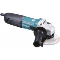
| Product Type | Angle Grinder |
| Brand | Makita |
| Model | GA6040C |
| Wheel Diameter | 150 mm (6") |
| Spindle Thread | M14 |
| No Load Speed | 4,000 - 9,000 min⁻¹ |
| Overall Length | 303 mm |
| Net Weight | 2.6 kg (according to EPTA 01/2003) |
| Safety Class | Double Insulation (Class II) |
| Speed Adjustment | Rotary dial from 1 to 5 |
| Electronic Functions | Constant speed control, soft start, overload protection |
| Mechanical Brake | No (only on model GA6041C) |
| Shaft Lock | Yes |
| Accidental Restart Protection | Yes (flashing red indicator light) |
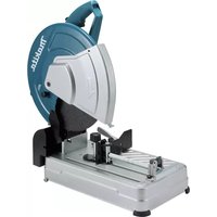
| Applications | Grinding, sanding, cutting of metals and stone, wire brushing |
| Supplied Accessories | Side handle, wheel guard, lock nut wrench |
| Maintenance | Clean ventilation slots regularly; use only Makita genuine spare parts |
| Sound Pressure Level | 87 dB(A) (uncertainty 3 dB(A)) |
| Vibration (grinding) | 6.5 m/s² (uncertainty 1.5 m/s²) |
Frequently Asked Questions - GA6040C MAKITA
User questions about GA6040C MAKITA
0 question about this device. Answer the ones you know or ask your own.
Ask a new question about this device
Download the instructions for your Garden shredder in PDF format for free! Find your manual GA6040C - MAKITA and take your electronic device back in hand. On this page are published all the documents necessary for the use of your device. GA6040C by MAKITA.
USER MANUAL GA6040C MAKITA
GB Angle Grinding Instruction Manual
Explanation of general view
| 1 S h a f t l o c | k2 Lock nut wrench | 24 Marking B |
| 2 Slide switch | 13 Ezynut | 25 Marking C |
| 3 Indication lamp (speed adjust-ing dial) | 14 Abrasive wheel | 26 Marking D |
| 15 Spindle | 27 Abrasive cut-off wheel/diamond wheel | |
| 4 Speed adjusting dial | 16 Arrow | |
| 5 Wheel guard | 17 Notch | 28 Wheel guard for abrasive cut-off wheel/diamond wheel |
| 6 Bearing box | 18 Flex wheel | |
| 7 S c r e w | 19 Plastic pad | 29 Wire cup brush |
| 8 Lever | 20 Sanding lock nut | 30 Wire wheel brush |
| 9 Lock nut | 21 Abrasive disc | 31 Exhaust vent |
| 10 Depressed center wheel | 22 Rubber pad | 32 Inhalation vent |
| 11 Inner flange | 23 Marking A |
SPECIFICATIONS
| Model GA404 | OC GA4041 | C GA4540C | GA4541C | GA5040C | GA5041C | GA6040C | GA6041C | |
| Wheel diameter 100 mm (4") 115 mm (4-1)/2") 125 mm (5") 150 mm (6") | ||||||||
| Spindle thread M | 10 M14 M14 M14 | |||||||
| Rated speed (n) /No load speed (n0) | 2,800 – 11,000 min-1 | 2,800 – 11,000 min-1 | 2,800 – 11,000 min-1 | 4,000 – 9,000 min-1 | ||||
| Overall length | 303 mm | 325 mm | 303 mm | 325 mm | 303 mm | 325 mm | 303 mm | 325 mm |
| Net weight | 2.3 kg | 2.6 kg | 2.5 kg | 2.7 kg | 2.5 kg | 2.7 kg | 2.6 kg | 2.8 kg |
| Safety class | ☐/II | |||||||
- Due to our continuing program of research and development, the specifications herein are subject to change without notice.
- Specifications may differ from country to country.
Weight according to EPTA-Procedure 01/2003
ENE048-1
Intended use
The tool is intended for grinding, sanding and cutting of metal and stone materials without the use of water.
ENF002-2
Power supply
The tool should be connected only to a power supply of the same voltage as indicated on the nameplate, and can only be operated on single-phase AC supply. They are double-insulated and can, therefore, also be used from sockets without earth wire.
GEA010-1
General Power Tool SafetyWarnings
WARNING Read all safety warnings and all instructions. Failure to follow the warnings and instructions may result in electric shock, fire and/or serious injury.
Save all warnings and instructions for future reference.
GEB033-6
GRINDER SAFETY WARNINGS
SafetyWarnings Common for Grinding, Sanding, Wire Brushing, or Abrasive Cutting-Off Operations:
- This power tool is intended to function as a grinder, sander, wire brush or cut-off tool. Read all safety warnings, instructions, illustrations and specifications provided with this power tool. Failure to follow all instructions listed below may result in electric shock, fire and/or serious injury.
- Operations such as polishing are not recommended to be performed with this power tool. Operations for which the power tool was not designed may create a hazard and cause personal injury.
- Do not use accessories which are not specifically designed and recommended by the tool manufacturer. Just because the accessory can be attached to your power tool, it does not assure safe operation.
- The rated speed of the accessory must be at least equal to the maximum speed marked on the power tool. Accessories running faster than their rated speed can break and fly apart.
- The outside diameter and the thickness of your accessory must be within the capacity rating of your power tool. Incorrectly sized accessories cannot be adequately guarded or controlled.
-
The arbour size of wheels, flanges, backing pads or any other accessory must properly fit the spindle of the power tool. Accessories with arbour holes that do not match the mounting hardware of the power tool will run out of balance, vibrate excessively and may cause loss of control.
-
Do not use a damaged accessory. Before each use inspect the accessory such as abrasive wheels for chips and cracks, backing pad for cracks, tear or excess wear, wire brush for loose or cracked wires. If power tool or accessory is dropped, inspect for damage or install an undamaged accessory. After inspecting and installing an accessory, position yourself and bystanders away from the plane of the rotating accessory and run the power tool at maximum no-load speed for one minute. Damaged accessories will normally break apart during this test time.
- Wear personal protective equipment. Depending on application, use face shield, safety goggles or safety glasses. As appropriate, wear dust mask, hearing protectors, gloves and workshop apron capable of stopping small abrasive or workpiece fragments. The eye protection must be capable of stopping flying debris generated by various operations. The dust mask or respirator must be capable of filtrating particles generated by your operation. Prolonged exposure to high intensity noise may cause hearing loss.
- Keep bystanders a safe distance away from work area. Anyone entering the work area must wear personal protective equipment. Fragments of workpiece or of a broken accessory may fly away and cause injury beyond immediate area of operation.
- Hold the power tool by insulated gripping surfaces only, when performing an operation where the cutting accessory may contact hidden wiring or its own cord. Cutting accessory contacting a "live" wire may make exposed metal parts of the power tool "live" and could give the operator an electric shock.
- Position the cord clear of the spinning accessory. If you lose control, the cord may be cut or snagged and your hand or arm may be pulled into the spinning accessory.
- Never lay the power tool down until the accessory has come to a complete stop. The spinning accessory may grab the surface and pull the power tool out of your control.
- Do not run the power tool while carrying it at your side. Accidental contact with the spinning accessory could snag your clothing, pulling the accessory into your body.
- Regularly clean the power tool's air vents. The motor's fan will draw the dust inside the housing and excessive accumulation of powdered metal may cause electrical hazards.
- Do not operate the power tool near flammable materials. Sparks could ignite these materials.
- Do not use accessories that require liquid coolants. Using water or other liquid coolants may result in electrocution or shock.
Kickback and RelatedWarnings
Kickback is a sudden reaction to a pinched or snagged rotating wheel, backing pad, brush or any other accessory. Pinching or snagging causes rapid stalling of the rotating accessory which in turn causes the uncontrolled power tool to be forced in the direction opposite of the accessory's rotation at the point of the binding.
For example, if an abrasive wheel is snagged or pinched by the workpiece, the edge of the wheel that is entering into the pinch point can dig into the surface of the material causing the wheel to climb out or kick out. The wheel may either jump toward or away from the operator, depending on direction of the wheel's movement at the point of pinching. Abrasive wheels may also break under these conditions.
Kickback is the result of power tool misuse and/or incorrect operating procedures or conditions and can be avoided by taking proper precautions as given below.
a) Maintain a firm grip on the power tool and position your body and arm to allow you to resist kickback forces. Always use auxiliary handle, if provided, for maximum control over kickback or torque reaction during startup. The operator can control torque reactions or kickback forces, if proper precautions are taken.
b) Never place your hand near the rotating accessory. Accessory may kickback over your hand.
c) Do not position your body in the area where power tool will move if kickback occurs. Kickback will propel the tool in direction opposite to the wheel's movement at the point of snagging.
d) Use special care when working corners, sharp edges etc. Avoid bouncing and snagging the accessory. Corners, sharp edges or bouncing have a tendency to snag the rotating accessory and cause loss of control or kickback.
e) Do not attach a saw chain woodcarving blade or toothed saw blade. Such blades create frequent kickback and loss of control.
SafetyWarnings Specific for Grinding and Abrasive Cutting-Off Operations:
a) Use only wheel types that are recommended for your power tool and the specific guard designed for the selected wheel. Wheels for which the power tool was not designed cannot be adequately guarded and are unsafe.
b) The guard must be securely attached to the power tool and positioned for maximum safety, so the least amount of wheel is exposed towards the operator. The guard helps to protect the operator from broken wheel fragments, accidental contact with wheel and sparks that could ignite clothing.
c) Wheels must be used only for recommended applications. For example: do not grind with the side of cut-off wheel. Abrasive cut-off wheels are intended for peripheral grinding, side forces applied to these wheels may cause them to shatter.
d) Always use undamaged wheel flanges that are of correct size and shape for your selected wheel. Proper wheel flanges support the wheel thus reducing the possibility of wheel breakage. Flanges for cut-off wheels may be different from grinding wheel flanges.
e) Do not use worn down wheels from larger power tools. Wheel intended for larger power tool is not suitable for the higher speed of a smaller tool and may burst.
Additional SafetyWarnings Specific for Abrasive Cutting-Off Operations:
a) Do not "jam" the cut-off wheel or apply excessive pressure. Do not attempt to make an excessive depth of cut. Overstressing the wheel increases the loading and susceptibility to twisting or binding of the wheel in the cut and the possibility of kickback or wheel breakage.
b) Do not position your body in line with and behind the rotating wheel. When the wheel, at the point of operation, is moving away from your body, the possible kickback may propel the spinning wheel and the power tool directly at you.
c) When wheel is binding or when interrupting a cut for any reason, switch off the power tool and hold the power tool motionless until the wheel comes to a complete stop. Never attempt to remove the cut-off wheel from the cut while the wheel is in motion otherwise kickback may occur. Investigate and take corrective action to eliminate the cause of wheel binding
d) Do not restart the cutting operation in the workpiece. Let the wheel reach full speed and carefully re-enter the cut. The wheel may bind, walk up or kickback if the power tool is restarted in the workpiece.
e) Support panels or any oversized workpiece to minimize the risk of wheel pinching and kickback. Large workpieces tend to sag under their own weight. Supports must be placed under the workpiece near the line of cut and near the edge of the workpiece on both sides of the wheel.
f) Use extra caution when making a "pocket cut" into existing walls or other blind areas. The protruding wheel may cut gas or water pipes, electrical wiring or objects that can cause kickback.
SafetyWarnings Specific for Sanding Operations:
a) Do not use excessively oversized sanding disc paper. Follow manufacturers recommendations, when selecting sanding paper. Larger sanding paper extending beyond the sanding pad presents a laceration hazard and may cause snagging, tearing of the disc or kickback.
SafetyWarnings Specific for Wire Brushing Operations:
a) Be aware that wire bristles are thrown by the brush even during ordinary operation. Do not overstress the wires by applying excessive load to the brush. The wire bristles can easily penetrate light clothing and/or skin.
b) If the use of a guard is recommended for wire brushing, do not allow interference of the wire wheel or brush with the guard. Wire wheel or brush may expand in diameter due to work load and centrifugal forces.
Additional safety warnings:
- When using depressed centre grinding wheels, be sure to use only fiberglass-reinforced wheels.
-
NEVER USE Stone Cup type wheels with this grinder. This grinder is not designed for these types of wheels and the use of such a product may result in serious personal injury.
-
Be careful not to damage the spindle, the flange (especially the installing surface) or the lock nut. Damage to these parts could result in wheel breakage.
- Make sure the wheel is not contacting the workpiece before the switch is turned on.
- Before using the tool on an actual workpiece, let it run for a while. Watch for vibration or wobbling that could indicate poor installation or a poorly balanced wheel.
- Use the specified surface of the wheel to perform the grinding.
- Watch out for flying sparks. Hold the tool so that sparks fly away from you and other persons or flammable materials.
- Do not leave the tool running. Operate the tool only when hand-held.
- Do not touch the workpiece immediately after operation; it may be extremely hot and could burn your skin.
- Always be sure that the tool is switched off and unplugged or that the battery cartridge is removed before carrying out any work on the tool.
- Observe the instructions of the manufacturer for correct mounting and use of wheels. Handle and store wheels with care.
- Do not use separate reducing bushings or adaptors to adapt large hole abrasive wheels.
- Use only flanges specified for this tool.
- For tools intended to be fitted with threaded hole wheel, ensure that the thread in the wheel is long enough to accept the spindle length.
- Check that the workpiece is properly supported.
- Pay attention that the wheel continues to rotate after the tool is switched off.
- If working place is extremely hot and humid, or badly polluted by conductive dust, use a short-circuit breaker (30 mA) to assure operator safety.
- Do not use the tool on any materials containing asbestos.
- Do not use water or grinding lubricant.
- Ensure that ventilation openings are kept clear when working in dusty conditions. If it should become necessary to clear dust, first disconnect the tool from the mains supply (use non metallic objects) and avoid damaging internal parts.
- When use cut-off wheel, always work with the dust collecting wheel guard required by domestic regulation.
- Cutting discs must not be subjected to any lateral pressure.
SAVE THESE INSTRUCTIONS.
WARNING:
DO NOT let comfort or familiarity with product (gained from repeated use) replace strict adherence to safety rules for the subject product. MISUSE or failure to follow the safety rules stated in this instruction manual may cause serious personal injury.
FUNCTIONAL DESCRIPTION
CAUTION:
- Always be sure that the tool is switched off and unplugged before adjusting or checking function on the tool.
Shaft lock (Fig. 1)
CAUTION:
- Never actuate the shaft lock when the spindle is moving. The tool may be damaged.
Press the shaft lock to prevent spindle rotation when installing or removing accessories.
Switch action (Fig. 2)
CAUTION:
- Before plugging in the tool, always check to see that the slide switch actuates properly and returns to the "OFF" position when the rear of the slide switch is depressed.
- Switch can be locked in "ON" position for ease of operator comfort during extended use. Apply caution when locking tool in "ON" position and maintain firm grasp on tool.
To start the tool, slide the slide switch toward the "I (ON)" position by pushing the rear of the slide switch. For continuous operation, press the front of the slide switch to lock it.
To stop the tool, press the rear of the slide switch, then slide it toward the "O (OFF)" position.
Indication lamp (Fig. 3)
The indication lamp Tights up green when the tool is plugged. If the indication lamp does not light up, the mains cord or the controller may be defective. The indication lamp is lit but the tool does not start even if the tool is switched on, the carbon brushes may be worn out, or the controller, the motor or the ON/OFF switch may be defective.
Unintentional restart proof
The tool does not start with the switch being lock-on even when the tool is plugged.
At this time, the indication lamp flickers red and shows the unintentional restart proof device is on function.
To cancel the unintentional restart proof, return the slide switch to "O (OFF)" position.
Speed adjusting dial (Fig. 4)
The rotating speed can be changed by turning the speed adjusting dial to a given number setting from 1 to 5.
Higher speed is obtained when the dial is turned in the direction of number 5. And lower speed is obtained when it is turned in the direction of number 1.
Refer to the below table for the relationship between the number settings on the dial and the approximate rotating speed.
For model GA4040C, GA4540C, GA5040C
| Number min | -1 (R.P.M.) |
| 1 | 2 |
| 2 | 4 |
| 3 | 6 |
| 4 | 8 |
| 5 | 1 |
012752
For model GA6040C
| Number min | -1 (R.P.M.) |
| 1 4,000 | |
| 2 5,000 | |
| 3 6,000 | |
| 4 7,000 | |
| 5 9,000 |
012756
CAUTION:
- If the tool is operated continuously at low speeds for a long time, the motor will get overloaded and heated up.
- The speed adjusting dial can be turned only as far as 5 and back to 1. Do not force it past 5 or 1, or the speed adjusting function may no longer work.
Electronic function
The tools equipped with electronic function are easy to operate because of the following features.
Constant speed control
Constant speed control provides fine finish by keeping the rotating speed constant under the loaded condition.
Soft start feature
Soft start feature suppresses starting shock.
Overload protector
When the load on the tool exceeds admissible levels, power to the motor is reduced to protect the motor from overheating. When the load returns to admissible levels, the tool will operate as normal.
Mechanical brake
For model GA4041C, GA4541C, GA5041C, GA6041C Mechanical brake is activated after the tool is switched off.
The brake does not work when the power supply is shut down with the switch still on.
ASSEMBLY
CAUTION:
- Always be sure that the tool is switched off and unplugged before carrying out any work on the tool.
Installing side grip (handle) (Fig. 5)
CAUTION:
- Always be sure that the side grip is installed securely before operation.
Screw the side grip securely on the position of the tool as shown in the figure.
8 0
Installing or removing wheel guard (For depressed center wheel, flap disc, flex wheel, wire wheel brush / abrasive cut-off wheel, diamond wheel) (Fig. 6, 7 & 8)
WARNING:
-
When using a depressed center wheel, flap disc, flex wheel or wire wheel brush, the wheel guard must be fitted on the tool so that the closed side of the guard always points toward the operator.
-
When using an abrasive cut-off / diamond wheel, be sure to use only the special wheel guard designed for use with cut-off wheels. (In some European countries, when using a diamond wheel, the ordinary guard can be used. Follow the regulations in your country.)
For tool with locking screw type wheel guard
Mount the wheel guard with the protrusions on the wheel guard band aligned with the notches on the bearing box. Then rotate the wheel guard around 180^ counterclockwise. Be sure to tighten the screw securely. To remove wheel guard, follow the installation procedure in reverse.
For tool with clamp lever type wheel guard
Pull the lever in the direction of the arrow after loosening the screw. Mount the wheel guard with the protrusions on the wheel guard band aligned with the notches on the bearing box. Then rotate the wheel guard around 180^ .
Tighten the wheel guard with fastening the screw after pulling lever in the direction of the arrow. The setting angle of the wheel guard can be adjusted with the lever. To remove wheel guard, follow the installation procedure in reverse.
Installing or removing depressed center wheel or flap disc (optional accessory) (Fig. 9 & 10)
WARNING:
- When using a depressed center wheel or flap disc, the wheel guard must be fitted on the tool so that the closed side of the guard always points toward the operator.
Mount the inner flange onto the spindle. Fit the wheel/disc on the inner flange and screw the lock nut onto the spindle.
To tighten the lock nut, press the shaft lock firmly so that the spindle cannot revolve, then use the lock nut wrench and securely tighten clockwise.
To remove the wheel, follow the installation procedure in reverse.
Super flange (Optional accessory)
Models with the letter F are standard-equipped with Super flange. Only 1/3 of efforts needed to undo lock nut, compared with conventional type.
CAUTION:
- Do not use super flange for models equipped with the mechanical brake. Otherwise it may loosen when the brake is activated.
Installing or removing Ezynut (optional accessory) (Fig. 11, 12, 13 & 14)
CAUTION:
- Do not use Ezynut with Super Flange or angle grinder with "F" on the end of the model No. Those flanges are so thick that the entire thread cannot be retained by the spindle.
Mount inner flange, abrasive wheel and Ezynut onto the spindle so that Makita Logo on Ezynut faces outside.
Press shaft lock firmly and tighten Ezynut by turning the abrasive wheel clockwise as far as it turns.
Turn the outside ring of Ezynut counterclockwise to loosen.
NOTE:
- Ezynut can be loosened by hand as long as the arrow points the notch. Otherwise a lock nut wrench is required to loosen it. Insert one pin of the wrench into a hole and turn Ezynut counterclockwise.
Installing or removing flex wheel (optional accessory) (Fig. 15)
WARNING:
- Always use supplied guard when flex wheel is on tool. Wheel can shatter during use and guard helps to reduce chances of personal injury.
Follow instructions for depressed center wheel but also use plastic pad over wheel. See order of assembly on accessories page in this manual.
Installing or removing abrasive disc (optional accessory) (Fig. 16)
NOTE:
- Use sander accessories specified in this manual. These must be purchased separately.
Mount the rubber pad onto the spindle. Fit the disc on the rubber pad and screw the sanding lock nut onto the spindle. To tighten the sanding lock nut, press the shaft lock firmly so that the spindle cannot revolve, then use the lock nut wrench and securely tighten clockwise.
To remove the disc, follow the installation procedure in reverse.
Installing or removing dust cover attachment (Optional accessory) (Fig. 17)
WARNING:
- Always be sure that the tool is switched off and unplugged before installing or removing the dust cover attachment. Failure to do so causes damage to the tool or a personal injury.
There are four pieces of dust cover attachment and each is used in one of different positions.
Set the dust cover attachment so that the marking (A, B, C or D) places as shown. Snap its pins in the vents.
Dust cover attachment can be removed by hand.
NOTE:
- Clean out the dust cover attachment when it is clogged with dust or foreign matters. Continuing operation with a clogged dust cover attachment will damage the tool.
OPERATION
WARNING:
- It should never be necessary to force the tool. The weight of the tool applies adequate pressure. Forcing and excessive pressure could cause dangerous wheel breakage.
- ALWAYS replace wheel if tool is dropped while grinding.
- NEVER bang or hit grinding disc or wheel onto work.
- Avoid bouncing and snagging the wheel, especially when working corners, sharp edges etc. This can cause loss of control and kickback.
- NEVER use tool with wood cutting blades and other saw blades. Such blades when used on a grinder frequently kick and cause loss of control leading to personal injury.

CAUTION:
- Never switch on the tool when it is in contact with the workpiece, it may cause an injury to operator.
- Always wear safety goggles or a face shield during operation.
After operation, always switch off the tool and wait until the wheel has come to a complete stop before putting the tool down.
Grinding and sanding operation (Fig. 18)
ALWAYS hold the tool firmly with one hand on housing and the other on the side handle. Turn the tool on and then apply the wheel or disc to the workpiece. In general, keep the edge of the wheel or disc at an angle of about 15^ to the workpiece surface.
During the break-in period with a new wheel, do not work the grinder in the B direction or it will cut into the workpiece. Once the edge of the wheel has been rounded off by use, the wheel may be worked in both A and B direction.
Operation with abrasive cut-off / diamond wheel (optional accessory) (Fig. 19)
The direction for mounting the lock nut and the inner flange varies by wheel thickness.
Refer to the table below.
| 100 mm (4") model Abrasive cut-off wheel Diamond wheel | |||
| Thickness: Less than 4 mm (5/32") | Thickness: 4 mm (5/32") or more | Thickness: Less than 4 mm (5/32") | Thickness: 4 mm (5/32") or more |
| 1 | 1 | 1 | 1 |
| 16 mm (5/8") | 16 mm (5/8") | 20 mm (13/16") | 20 mm (13/16") |
| 3 | 3 | 3 | 3 |
| 1. Lock nut 2. Abrasive cut-off wheel 3. Inner flange 4. Diamond wheel | |||
| 115 mm (4-1/2") / 125 mm (5") / 150 mm (6") model Abrasive cut-off wheel Diamond wheel | |||
| Thickness: Less than 4 mm (5/32") | Thickness: 4 mm (5/32") or more | Thickness: Less than 4 mm (5/32") | Thickness: 4 mm (5/32") or more |
| 1 | 1 | 1 | 1 |
| 22.23 mm (7/8") | 22.23 mm (7/8") | 22.23 mm (7/8") | 22.23 mm (7/8") |
| 3 | 3 | 3 | 3 |
| 1. Lock nut 2. Abrasive cut-off wheel 3. Inner flange 4. Diamond wheel | |||
012746

WARNING:
- When using an abrasive cut-off / diamond wheel, be sure to use only the special wheel guard designed for use with cut-off wheels. (In some European countries, when using a diamond wheel, the ordinary guard can be used. Follow the regulations in your country.)
-
NEVER use cut-off wheel for side grinding.
-
Do not "jam" the wheel or apply excessive pressure. Do not attempt to make an excessive depth of cut. Overstressing the wheel increases the loading and susceptibility to twisting or binding of the wheel in the cut and the possibility of kickback, wheel breakage and overheating of the motor may occur.
-
Do not start the cutting operation in the workpiece. Let the wheel reach full speed and carefully enter into the cut moving the tool forward over the workpiece surface. The wheel may bind, walk up or kickback if the power tool is started in the workpiece.
-
During cutting operations, never change the angle of the wheel. Placing side pressure on the cut-off wheel (as in grinding) will cause the wheel to crack and break, causing serious personal injury.
- A diamond wheel shall be operated perpendicular to the material being cut.
Operation with wire cup brush (optional accessory) (Fig. 20)
CAUTION:
- Check operation of brush by running tool with no load, insuring that no one is in front of or in line with brush.
- Do not use brush that is damaged, or which is out of balance. Use of damaged brush could increase potential for injury from contact with broken brush wires.
Unplug tool and place it upside down allowing easy access to spindle. Remove any accessories on spindle. Thread wire cup brush onto spindle and tighten with supplied wrench. When using brush, avoid applying too much pressure which causes over bending of wires, leading to premature breakage.
Operation with wire wheel brush (optional accessory) (Fig. 21)
CAUTION:
- Check operation of wire wheel brush by running tool with no load, insuring that no one is in front of or in line with the wire wheel brush.
- Do not use wire wheel brush that is damaged, or which is out of balance. Use of damaged wire wheel brush could increase potential for injury from contact with broken wires.
- ALWAYS use guard with wire wheel brushes, assuring diameter of wheel fits inside guard. Wheel can shatter during use and guard helps to reduce chances of personal injury.
Unplug tool and place it upside down allowing easy access to spindle. Remove any accessories on spindle. Thread wire wheel brush onto spindle and tighten with the wrenches.
When using wire wheel brush, avoid applying too much pressure which causes over bending of wires, leading to premature breakage.
MAINTENANCE
CAUTION:
- Always be sure that the tool is switched off and unplugged before attempting to perform inspection or maintenance.
- Never use gasoline, benzine, thinner, alcohol or the like. Discoloration, deformation or cracks may result.
The tool and its air vents have to be kept clean. Regularly clean the tool's air vents or whenever the vents start to become obstructed. (Fig. 22)
To maintain product SAFETY and RELIABILITY, repairs, carbon brush inspection and replacement, any other maintenance or adjustment should be performed by Makita Authorized Service Centers, always using Makita replacement parts.
OPTIONAL ACCESSORIES
CAUTION:
- These accessories or attachments are recommended for use with your Makita tool specified in this manual. The use of any other accessories or attachments might present a risk of injury to persons. Only use accessory or attachment for its stated purpose.
If you need any assistance for more details regarding these accessories, ask your local Makita Service Center.
- Dust cover attachment
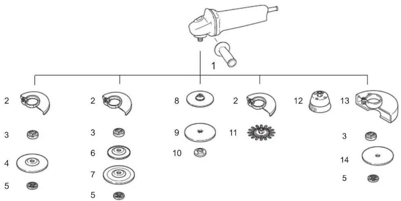
| 100 mm (4") model 115 | mm (4-1/2") model 125 mm | (5") model 150 mm (6") model | ||
| 1 | G | r | ||
| 2 Wheel Guard (for grinding wheel) | ||||
| 3 Inner flange 30 | Inner flange 42 Super flange 47 *1 | Inner flange 42 Super flange 47 *1 | Inner flange 42 Super flange 47 *1 | |
| 4 Depressed center wheel/Flap disc | ||||
| 5 Lock nut 10-30 | Lock nut 14-45 Ezy nut *2 | Lock nut 14-45 Ezy nut *2 | Lock nut 14-45 Ezy nut *2 | |
| 6 Plastic pad Plastic pad Plastic | pad - | |||
| 7 Flex wheel Flex wheel Flex wheel | wheel - | |||
| 8 Rubber pad 76 Rubber pad 100 Rubber pad 1 | 15 Rubber pad 125 | |||
| 9 | Abrasive disc | |||
| 10 | Sanding lock nut 10-30 | Sanding lock nut 14-48 | Sanding lock nut 14-48 | Sanding lock nut 14-48 |
| 11 | Wire wheel brush | |||
| 12 | Wire cup brush | |||
| 13 | Wheel Guard (for cut-off wheel) *3 | |||
| 14 | Abrasive cut-off wheel/Diamond wheel | |||
| - | Lock nut wrench 20 | Lock nut wrench 35 | Lock nut wrench 35 | Lock nut wrench 35 |
Note:
1 Do not use Super flange with a grinder equipped with a brake function.
2 Do not use Super flange and Ezynut together.
*3 In some European countries, when using a diamond wheel, the ordinary guard can be used instead of the special guard covering the both side of the wheel. Follow the regulations in your country.
012760
NOTE:
- Some items in the list may be included in the tool package as standard accessories. They may differ from country to country.
Noise
The typical A-weighted noise level determined according to EN60745:
Model GA4040C, GA4540C, GA5040C
Sound pressure level (L_pA) : 86 dB (A)
Sound power level (L_WA) : 97 dB (A)
Uncertainty (K): 3 dB (A)
Model GA6040C
Sound pressure level (L_pA) .. 87 dB (A)
Sound power level (L_WA) : 98 dB (A)
Uncertainty (K): 3 dB (A)
Model GA4541C
Sound pressure level (L_pA) : 83 dB (A)
Sound power level (L_WA) : 94 dB (A)
Uncertainty (K): 3 dB (A)
Model GA5041C, GA6041C
Sound pressure level (L_pA) : 84 dB (A)
Sound power level (L_WA) : 95 dB (A)
Uncertainty (K): 3 dB (A)
Wear ear protection
ENG900-1
Vibration
The vibration total value (tri-axial vector sum) determined according to EN60745:
Model GA4040C
Work mode: surface grinding with normal side grip
Vibration emission (a_h,AG) : 5.0~m / s^2
Uncertainty (K): 1.5m / s^2
Work mode: surface grinding with anti vibration side grip
Vibration emission (a_h,AG) : 5.0~m / s^2
Uncertainty (K): 1.5m^2s^2
Work mode: disc sanding with normal side grip
Vibration emission (a_h,ps) : 3.0~m / s^2
Uncertainty (K): 1.5m / s^2
Work mode: disc sanding with anti vibration side grip
Vibration emission (a_h,DS) : 2.5m / s^2 or less
Uncertainty (K): 1.5m / s^2
Model GA4540C
Work mode: surface grinding with normal side grip
Vibration emission (a_h,AG) : 6.0 m/s²
Uncertainty (K): 1.5m / s^2
Work mode: surface grinding with anti vibration side grip
Vibration emission (a_h,AG) .. 5.5m / s^2
Uncertainty (K): 1.5m / s^2
Work mode: disc sanding with normal side grip
Vibration emission (a_h,DS) : 2.5m / s^2
Uncertainty (K): 1.5m / s^2
Work mode: disc sanding with anti vibration side grip
Vibration emission (a_h,DS) : 2.5m / s^2
Uncertainty (K): 1.5m / s^2
Model GA5040C
Work mode: surface grinding with normal side grip
Vibration emission (a_h,AG) : 6.5 m/s²
Uncertainty (K): 1.5m / s^2
Work mode: surface grinding with anti vibration side grip
Vibration emission (a_h_AG) .. 5.5m / s^2
Uncertainty (K): 1.5m / s^2
Work mode: disc sanding with normal side grip
Vibration emission (ahDS) .. 2.5m / s^2
Uncertainty (K): 1.5m^3 /s^2
Work mode: disc sanding with anti vibration side grip
Vibration emission (ahDS) .. 2.5m / s^2
Uncertainty (K): 1.5m^3 /s^2
Model GA6040C
Work mode : surface grinding with normal side grip
Vibration emission (ahAG) .. 6.5m / s^2
Uncertainty (K): 1.5m^3 /s^2
Work mode: surface grinding with anti vibration side grip
Vibration emission (ahAG) .. 6.0~m / s^2
Uncertainty (K): 1.5m / s^2
Work mode: disc sanding with normal side grip
Vibration emission (a_h,DS) : 2.5m / s^2
Uncertainty (K): 1.5m / s^2
Work mode: disc sanding with anti vibration side grip
Vibration emission (a_h,DS) : 2.5 m/s² or less
Uncertainty (K): 1.5m / s^2
Model GA4541C, GA6041C
Work mode: surface grinding with normal side grip
Vibration emission (ahAG) .. 6.5m / s^2
Uncertainty (K): 1.5m^2 /s^2
Work mode: surface grinding with anti vibration side grip
Vibration emission (a_b G):5.5m / s^2
Uncertainty (K): 1.5m / s^2
Work mode: disc sanding with normal side grip
Vibration emission (a_b,PS) : 2.5m / s^2 or less
Uncertainty (K): 1.5m / s^2
Work mode: disc sanding with anti vibration side grip
Vibration emission (a_h_DS) .. 2.5m / s^2 or less
Uncertainty (K): 1.5m^3 /s^2
Model GA5041C
Work mode: surface grinding with normal side grip
Vibration emission (a_h,AG) : 7.0~m / s^2
Uncertainty (K): 1.5m / s^2
Work mode: surface grinding with anti vibration side grip
Work mode: disc sanding with normal side grip
Vibration emission (a_h_DS) .. 2.5m / s^2 or less
Uncertainty (K): 1.5m / s^2
Work mode: disc sanding with anti vibration side grip
Vibration emission (a_h_DS) .. 2.5m / s^2 or less
Uncertainty (K): 1.5m / s^2
ENG902-1
- The declared vibration emission value has been measured in accordance with the standard test method and may be used for comparing one tool with another.
- The declared vibration emission value may also be used in a preliminary assessment of exposure.
- The declared vibration emission value is used for main applications of the power tool. However if the power tool is used for other applications, the vibration emission value may be different.

WARNING:
- The vibration emission during actual use of the power tool can differ from the declared emission value depending on the ways in which the tool is used.
- Be sure to identify safety measures to protect the operator that are based on an estimation of exposure in the actual conditions of use (taking account of all parts of the operating cycle such as the times when the tool is switched off and when it is running idle in addition to the trigger time).
ENH101-15
For European countries only
EC Declaration of Conformity
We Makita Corporation as the responsible manufacturer declare that the following Makita machine(s):
Designation of Machine: Angle Grinding
Model No./ Type: GA4040C, GA4540C, GA5040C,
GA6040C, GA4541C, GA5041C, GA6041C
are of series production and
Conforms to the following European Directives: 2006/42/EC
And are manufactured in accordance with the following standards or standardised documents: EN60745
The technical documentation is kept by our authorised representative in Europe who is:
Makita International Europe Ltd.
Michigan Drive, Tongwell,
Milton Keynes, Bucks MK15 8JD, England
30.8.2011

Tomoyasu Kato
Director
Makita Corporation
3-11-8, Sumiyoshi-cho,
Anjo,Aichi,446-8502,JAPAN
Descriptif
ACCESSIONS EN OPTION

ATTENTION :
GA6040C, GA4541C, GA5041C, GA6041C
Michigan Drive, Tongwell,
Milton Keynes, Bucks MK15 8JD, Angleterre
30.8.2011
Tomoyasu Kato
Director
Makita Corporation
3-11-8, Sumiyoshi-cho,
Anjo, Aichi, 446-8502, JAPAN
Übersicht
Model GA4541C, GA6041C
GA6040C, GA4541C, GA5041C, GA6041C
Michigan Drive, Tongwell,
Milton Keynes, Bucks MK15 8JD, England
30.8.2011

Tomoyasu Kato
Direktor
Makita Corporation
3-11-8, Sumiyoshi-cho,
Anjo, Aichi, 446-8502, JAPAN
Visione generale
Modello GA4040C, GA4540C, GA5040C
Livello pressione sonora (LpA) :86 dB A Livello potenza sonora (LWA) :97 dB A Incertezza (K):3 dB A
Modello GA6040C
Livello pressione sonora (LpA) :87 dB A Livello potenza sonora (LWA) :98 dB A Incertezza (K):3 dB A
Modello GA4541C
Livello pressione sonora (LpA) :83 dB A Livello potenza sonora (LWA) :94 dB (A) Incertezza (K): 3 dB (A)
Modello GA5041C, GA6041C
Livello pressione sonora (LpA) ..84 dB A Livello potenza sonora (LWA) ..95 dB (A) Incertezza (K):3 dB (A)
Modello GA4541C, GA6041C
Michigan Drive, Tongwell,
Milton Keynes, Bucks MK15 8JD, England
30.8.2011
Tomoyasu Kato
Aministratore
Makita Corporation
3-11-8, Sumiyoshi-cho,
Anjo, Aichi, 446-8502, JAPAN
OPTIONELE ACCESSOIRES
1 LET OP:
Model GA4040C, GA4540C, GA5040C
Geluidsdrukniveau (L_pA) : 86 dB (A)
Geluidsenergie-niveau (_WA) : 97 dB (A)
Onnauwkeurigheid (K): 3 dB (A)
Model GA6040C
Geluidsdrukniveau (L_pA) : 87 dB (A)
Geluidsenergie-niveau (L_WA) : 98 dB (A)
Onnauwkeurigheid (K): 3 dB (A)
Model GA4541C
Geluidsdrukniveau (L_PA) : 83 dB (A)
Geluidsenergie-niveau (L_WA) : 94 dB (A)
Onnauwkeurigheid (K): 3 dB (A)
Model GA5041C, GA6041C
Geluidsdruk niveau (L_pA) : 84 dB (A)
Geluidsenergiee-niveau (_WA) : 95 dB (A)
Onnauwkeurigheid (K): 3 dB (A)
Draag oorbeschemers
ENG900-1
Trilling
Model GA4541C, GA6041C
GA6040C, GA4541C, GA5041C, GA6041C
in sériearend geproduceden
Michigan Drive, Tongwell,
Milton Keynes, Bucks MK15 8JD, England
30.8.2011
Tomoyasu Kato
Directeur
Makita Corporation
3-11-8, Sumiyoshi-cho,
Anjo, Aichi, 446-8502, JAPAN
Modelo N/Tip: GA4040C, GA4540C, GA5040C, GA6040C, GA4541C, GA5041C, GA6041C
Michigan Drive, Tongwell,
Milton Keynes, Bucks MK15 8JD, Inglaterra
30.8.2011
Tomoyasu Kato
Director
Makita Corporation
3-11-8, Sumiyoshi-cho,
Anjo, Aichi, 446-8502, JAPAN
Explicaçao geral
Michigan Drive, Tongwell,
Milton Keynes, Bucks MK15 8JD, Inglaterra
30.8.2011
Tomoyasu Kato
Director
Makita Corporation
3-11-8, Sumiyoshi-cho,
Anjo, Aichi, 446-8502, JAPAN
For model GA4040C, GA4540C, GA5040C
| Tal min | -1 (R.P.M.) |
| 1 | 2 |
| 2 | 4 |
| 3 | 6 |
| 4 | 8 |
| 5 | 1 |
012752
For model GA6040C
| Talmin | -1 (R.P.M.) |
| 1 | 4 |
| 2 | 5 |
| 3 | 6 |
| 4 | 7 |
| 5 | 9 |
012756
FORSIGTIG:
For model GA4041C, GA4541C, GA5041C, GA6041C
Model GA4040C, GA4540C, GA5040C
Lydtryksniveau (LpA) :86 dB A Lydeffektniveau (LWA) :97 dB (A) Usikkerhed (K):3 dB (A)
Model GA6040C
Lydtryksniveau (LpA) :87 dB A Lydeffektniveau (LWA) :98 dB A Usikkerhed (K):3 dB A
Model GA4541C
Lydtryksniveau (LpA) :83 dB A Lydeffektniveau (LWA) :94 dB A Usikkerhed (K):3 dB A
Model GA5041C, GA6041C
Lydtryksniveau (LpA) :84 dB A Lydeffektniveau (LWA) :95 dB A Usikkerhed (K):3 dB A
Baer horevaern
ENG900-1
Vibration
Vibrations totalvardi (tre-aksial vektorsum) bestemt i overensstemmelse med EN60745:
Model GA4040C
Model GA4541C, GA6041C
GA6040C, GA4541C, GA5041C, GA6041C
Michigan Drive, Tongwell,
Milton Keynes, Bucks MK15 8JD, England
30.8.2011
Tomoyasu Kato
Direktør
Makita Corporation
3-11-8, Sumiyoshi-cho,
Anjo, Aichi, 446-8502, JAPAN
Nepiypaipn yevikns atroyns
1 EAptnma Kkεiδμatoc ágova
2 Kulióevoδiakottn
3 EvEikTnKn luxvia (ETIIAOyEaC puOmuon taXutntac)
4 EtnioyacpuOmuonstaxutntac
5 PpOuλaKtnpaTpoXou
6 Kβωτιο εδραης
7 Biδα
8 MoxAoS
9 Naξiμδiασφλion
10 Tpoxoc xaunlambdaevou kevtpou
11EoWTepiKn Avtca
12 Kλειδί παξμαδιού ασφαλιούς
13 Ezynut
14 Tpoxoc i a v o n s
15 Atpaktos
16 Béλος
17 EyKoTn
18 EukamtoS δiokos
19 Paaotiko Tελμa
20 IaImuabi aopaiionc triipiaatoc
21 Diokos λειανος
22 Eλασικό πελμα
23 Evδειξη A
24 Evoi B
25 Evoi C
26 Evδειη D
27 Tpoxos avonks ktnic/ diaavtotpoxos
28 Ppouaktnpa Tpoou yia tpoxo Aiaavon Kottc/ diaqavtotpoxó
29 Suplevni BOpToa oxHuaTc Kouttac
30 Supleptivn Bouproa oxmuatoctpoxou
31 Avoiμa εξóδou αερα
32 Avoiya eiooou aepa
TEXNIKA XAPAKTHPII TIKA
To epyaleio Tpoopicetai yia tn aeivon, triiipko kai KOTIEc mtaaikwv kai TTepivwv uikwv xwiC tn xpno nvepou.
ENF002-2
Peuapotn
To unxavnpa npeTie va ouvdeetai mvo o Tnapoxn peuatoC tnc idiac taonc me autn tiou avapepetai otnv Tiivakida kataaKeuaotou kai mtopei va aeitoupynoei movo evaalaooepoovopaoikocpu. Ta unxavnpata auta exouv dimn movwnkai kat aouvetia, mtopouv va ouvdethetav oe akpoedktesxwipc opupa yeiowng.
GEA010-1
Evikcs poeidomoinoeic aqaaiaa yia to nEKTpiko epaaeio

NPOEIAOIOIHJH AiaβaTe oAεS TIS
TPOEIOIoioei aopaaieac kai oae TIG onyiec. H un npon Tuv TPOeIOIoioewv kai onyiwv evexetai va kataanxi e nektpoTTnxi, TUPkayia n/kai oapo Tpaumatio.
Quale 6AeT TIO POEIOIIOEIG KAI TIG ONYIEG YIA
muAAovtik napatoutn.
GEB033-6
AIEIANTHPA — IPOEI O OH E A A EIA
PpoeioiOeic aopaaia, Koivc yia epyaiecs Aiaovns, yuaoxaptiao, kaapouu eupaotoboutn kottns:
- Auto to nλεκτρικό εργαλείο προριζεται για xρήση ως εργαλείο λείανος, yuaλοχαρτίσματος, καθαρισμού με συματόβουρτος κοπής. Διαβάσε ὅλες τις προειδότοιησείς ασφαλείας, έδηγίς, εικόνογαρφήσεις και προδίαγραφές του παρέχονται με Auto to nλεκτρικό εργαλείο. Αμέλείαν ακολούθησετε ὅλες τις έδηγίς τιου avayραφονται παρακάτω μιποpeiν αέχει ως απότέλεσμα nλεκτροπληία, φωτία ἡ/και προσωτικό τραματίσμο.
- ouviotatai n ekteleon epyaowv otiaawons auto to nAektpiko epyaleio. Aietoupyies yia TIC oTIOIEs TO nAektpiko auto epyaleio dEvexi oxediaotei mTiopei va oniuoynooukivduvo kai va TTpokaeeouv TPOOWTIKO Tpaumatioo.
- Mn xpnoiopoioite Egaptnmuata Tou eivai EIOIKA OXeOIAOmeva KAI OUVIOTeVA aTO Tov KAATAOKEuaOTn Tou Epyaieiou. AIIwCs KAI MVO ETEIDTo EAptnma UTOpei va PPOaPTn0ei 0To Epyaleio, auto EEAQaLIeI aQaH N LEIToupyia.
-
H ovopaotikn taxutnta Tou esaptnmuos TpeTie Iva eivai toulaxiotov ion me tny meyiota taxutnta Tou eivai onneiwevn oTo nAekptiko epyaia. Eaptnmuata Tou aeitoupyouv taxutepa aTIO tv ovopaotikn taxutnta Touc mtopei va OTtaoov kai va ektoeueoov.
-
H E\xi 蛋 epikn iaeTPOs KAI TO TApXoTou EapntmuToC Oa CnpTeIvaEivaipeOa Ota opia IKavotntac Tou EpyaLeiou OaC.Eapntmuata n Owtou eeyooS eV mTropov va Tpoqulaaxouv n va EeYxOouv Etnapkowc.
- To Tns OTNS TPOOAPooynC Oe agovawTuv TPOxWv, TELaTuWv (TAToupeC), BaoewuUToataPngs n TuXov aALwV EApTnMaTuW TPeTTIva TaipiaCe ITOAUTWCOTOV aGova METABOONS KIVNGTou NAEKTPIKOU Epyaleiou. EApTnAutaE ONc TPOoAPooync OE aGova TOnBev TaipiaZouv ME TOV EGOITIAIOyEYkataOtaonCS Tou NAEKTPIKOU Epyaleiou 0a LEIToupyouv XwpiCi IOppotia, 0a Dovouvtai UTEpBoIAk kAI MTopei va TPOkaEoouv ATIWEAIA ELevyou.
- Mn xpnoiopoioite Eaptnma Tou exe utootei aBn. Piv aTcKaTe XpO, va Eetace To Eaptnma, OTWs LEIAVTIKOUC TPOXOUc, Yia pviouata kai pwye, tn Baon utooptnpis yia pwye, pnN n utepboikn 0bpopa, tn oupuatoBouptoa yia xaapa n payiaeva oupuata. Eav to nAektpko epyaaleio n to Eaptnma Teoei katw, eEySTo yia Znpie C npooapooTE eva kaLo EAptnma. Meta tov Eleyxo kai tv NPOoAPoyn Evoc EApntmuatoc, ATOUAKPVtheEoeic kai oYupw Oac atto To ETTIEBO TEPiOPOph TS Ugaptmuatoc KAI apnote OE AEIToupyia TO NAEKTPIKO epyaaleio OE MEyIOTN TAXUTNTA Xwpic FOPTIO yEAETTO. Eapntmuata Me Znmuie Gtheta diaAUoov kataov xpovo autnc tsckoiu
- Na φopáte atoipó ÉGOTLIOμo TPOOtaiac Avaloya μe TnV εpapouyn, va xpnoiμoTIOIE TPOOWTIDA TPOOtaiac, TPOOATEUTIKA yuaia-tpooswiides n yuaia TPOOtaiac. Otav aTaitai, va φopáte μασka σkovns, TPOOATEUTIKA akons, yavTIA KAI TODIa Ouvεpyeiou IKAVa va napexouv TPOOtaia ato Ta EKTIVAOOμeva μikpa θpaʊμata λoyw TNS λεiavons n Tou TEμaxiou EPaOSIAC. H μaoka OKOVNS n oukeun avativonc TIPETEVA eivai IKAVN va φiltpapei σωpatidia TAPAYOEVA aTTO TIC λεitoupyie cαç. Napatetapévn EkθeON e θópuβo uynanç ouxvotntoc μTOpEVA TPOKAeOI απWλEA iakons.
9.Kpatate Tou yupw OaOe Mia aopaa n anoataon ano Tov Xwpo Epyaioac. Otoiooohnote EIOEpxoEvos oTo xwpo epyaioac TpeTnei va Popa atoiko TPOoTateutiko EOTAIIOIO. Teuaxia aanto to avtikeiue vepyaoic n anto eva otuaevo Eaptnma uTopei va ekivaxOouv maKpua kai va Tpokaaleouv Tpaumatoio Tepav tnc aeeons Tepioxns Epyaioac. -
Kpatate to nEeKtpiO epyaeeio mvo ato tic moovwueves ETIpaveies Kpatnmuots, otav ektealeite mi epyaia oTou to eaptnma kottnc mtopei va eepei e TApn me Kpumuvecs kaawdiwoeic n kai e To biKO Tou Kaawdo. ZTEpiTTwn Etaqns Tou Eaptnmuoc Kotnnc m npkpofo pKaWIO, mtoei ta EkTeeieva metaaikc eaptnmaTa Tou nEeKTPiOu epyaieou vakataoov Ta ibia nEeKtpoPopa kai va Tpokaedouv nEeKtpoiAnxi aTo xeiipotn.
-
KpatnoTo Kaawio paKpua aTo TEPiOpeoEv OApntma.Eav XaTe TOV EeYxo, To Kaawio mTOpEva KOTei n va Tiaotei KA TO Xepi oas mTOpEVA TpaBnxEi MEOA OTO TEPiOteoEv OApntma.
- Noté μην τοῦ θεῖτε To ηεκτρικό εργαλείο Kατω Μέχρι Φεξαρθμαν αν ἐχει σαταμαποει τελείως. To περιστρεφόμενο εξαρθμα μτορείνα πίασει τήν εἰπράνεια και να τραβήξει Φηλεκτρικό εργαλείο εξω ατὸν ἐλεγχο σας.
- Mn xeipizote To nAekptko Epyaaleio Evw To taeapepete OTo TLEUPO aC. TuXia eTAPn ME TO TEPiOTpeoEv oEAptnma mTOpEi va TpOKaEoei TIAIOO OTo pouxa oac kai va TpaBnEi To EAptnma eOa oTo oWua oac.
- Kaθapiετε TAKTIKA TIG OTIE GAEPIAμO Tou ηεκτριού εργαλείου. O avεμισηρας Tou KIVπηρα θα ταβηξει ην σκόνη μεδο στο περβλημα KAI UΠερβολικ Μουκέντρωσι πίνισματων μεταλλου μΠοει έντρολεόει κίνουνο ηεκτροπιληξίας.
- Mn xeiipieoTe to nEeKtpiok epyaleio kovTa oE uAekta uiká. TIVnpec mTopei va avapaleouv ta ulikac auta.
- Mn xpnoiomoeite esapntnata Tou xpeiaovta uuktikauypa.Hxpon vepou n aawv uuktikuw uypwuTopei va Tpokaaleounv NktpoTTnEia n ook.
OTIOaKtioKa KAI OXETIKc TPOEIDOTIOeIc
H avakpoun (oTIOOlaKTIa) eivai iia gavikn avidpaon Tou EPyaleiou loyw oouphiYnc n okaawmuTou TEPiOTpePoeVou TPOXou, TcBaoNC uTOoTnpEiNc, TcBouptaaC n tuxov aALou EApntmuatoC. H ouqivn to kAomega Ppokaei Taxeia anwaleia Eevxou Tou TEPiOTpePoeVou EApntmuatoC to OTIOIO stouveeia UToxpeewto AVEEAEYkTO nEKTpiKO epyaleio 0 TEPiOTpoN AVtIeTN aTIO EKEIVN Tou EApntmuatoC tO Oneio EPTLOKnc.
Tia napadeyu, ev evac aeavikoc tpoxoc pieAe iO ouqyfn n okaawma oTO teuxio epyaoiag, n akun tou TPOXOU TO EIOPEXTAI OTO anueio ouoipvnc Evexetai va oakaei tvn EITpaveia Tou uikoou POKaWvtaC Tnv avannoan n to kIoTou Tou TPOXOU. O tpoxoc Evexetai va avattnoanei npoc to epos Tou xeiipotn n avtieta va atopakpvthei aTo autov, avaloya uT npopa TEPiOtpoqns Tou TPOXOU OTO anoeio ouoivnc. Yto autcTGouvthke, oi TPOXOI aeavon c Evexetai ETionc va untoouvthetaaon.
To otiooakiaiv aotateaoka kncxnpontou nAekpiokou evaleiou /kai eovpauevwv xeipoiuov n ouvwnkwv kai tropei va atnopeuxtheta i TIC KAATAANAE CTPOUALAEiOttowc ibovtai npakatw.
EttIaEv TpoeIdoToiOnoeic aOaAeiac:
- Otav xpnoiouoieTre poxouc eiaovn exaunlo kevtpo, povtioe oI tpoxoi va fepouv evioxuon an oivc yuaiou mvo.
- Mny XPHIIMONIOIEITE NOTE KwOwvoEideis Tpoxouc aeavons Tepaç ue autov to Aiavtnpa. Autoc o Aiavtnpac Dv Exei oxoiaotei ia autouc Touc TUTouc TPOXuv kai n xpnan Evoc TeTOIOU TTPOIOVTOC EvExeTai va TpOKAeoe I Ooapop Taupatio.
- IpooeTe wote va unv TpokaloeTe OTOV agova metadoon ts Kivnong, oTo TEa (Tatoupa) (Idiaitepa OTNV ETTiPaveia EYkataoTaonc) n oTo aOphiAIOtiko TEPIKoxlio. Tuxov BAlaBn OTo aOuyKEpImuEva Mepn 0a MTropoue va kataanxi e O pauOn Tou Tpoxou.
- Φροντίσε Τροχός συ μήν ἐρχεται σε επαφήμε το τεμάχιο ἔργασίας πρίν από ηύν ενεργοτοῦση του διακόπη.
- Piv aTn xPon Tou TPOXou Tavw oE TpaymuKo TEaXIO EpyaiaC, apnoTe Tov oE Aeioupyia YIA MIKPO XPOVIKO DiOtnua. Iapatnpnte EAV UNTAPXouv Dovnaic n TaIavTeUON Tou UTOnNawouv KaKn EYkataaTaN TPOXo ME KAKI IOoppoia.
- Xpnoiopoioiote TnV Tpokaopoiouevn ETIpaiveia Tou Tpoxou yia va EKTeIeOeTe TnV Epyaia Ieiaavons.
- Na eiote TPOOeTKIOI ME TIG EKTIVAOOoVEc OTiIEc. KpatnoTE TO epyaIeio ME TpOTo wOte OI OTiIEc va EKTIVaOoovTai paKpa aTO To oWpa OaC KAI aAa atoMa n EUFAeKTA uIAka.
-
Mny aqnvTe to epyaIeio avaupevo. XeiPiZeOTe To epyaIeio mvo otav to kpatate oTo xepi.
-
Mny ayyiTeTo Teayio Epyaioa aeoos mEta Tn Aitoupyia. Mtopei va eivai utepoikka Kauro kai va Tpokaloei eykauma.
- Na φροντίζετε πάντα υωτεν αέχει απένεργοτοιηθει και απούνδεθει το εργαλείοι από την τηραοχή Πεύματος ἡν αέχει αφαίρεθείη Θήκη μπαταρίων πρίν από την εκτέλεση Οτοίασθήποτε εργασίας στό εργαλείο.
- MeIeIeTIO TIG OINyIEC TOU KATAOKEuaOTN YIA OoATn TOnTOEETNOKAI XpON TOW TPoxWv. XeiPiTeTE KAI aTOnkEuaTe Tous TPOXouc ME PPOVtioa.
- Mn xnpoiopoite ixwpiotc outoaies n Tpooapouoyic ia va npoopauoote Tpoxouc meyao nn pnoopauoyns e agova.
- Xpnoiopoioieite kataaannae yia to epyaieio.
- Tia epyaieia oTa OTIOIA TTPOKEITAI VA TOIOETnTei TPOXOS OENI N EOTIEIPWMA, OIVOUPEUTEITE OTI TO OTIEIPWMA OTOV TPOXo EXE IETAPKcS uNKOs YIA vA dEXTEI TO uNKoTNS AGova.
- Eλεγξε οπι Μηχανημα Αυτοστηρίζει τι Σταθερά.
- Ipoose 0ti o Tpoxos ouvexizv a Tepiotpeetai akoun kai apou to unxavna exe i
- Eav to epos epyaiaeivai nolu zetoto kai uypo, n utapxiei noa aywyimn okovn, xpnoiopoioeiote eva aqpaaleioiaokottnpaxukukawmuos (30 mA) yia va eioe oiyoupoi ia aqpaanl aeitoupyia.
- Mn xpoioptoiTe To mnxavma o Kaveva uAiko Tou TEpiexi aOeTo.
- Mn xpoiopoioite VEPO n AITAVIKo TPOxionc.
- ΣιγουρεUTE iε Οι τα Απες εξαερισμού διαπρούνται αυοίχτα ὄταν εργαζεθε σε έκονισμένο περιβαλλον. Eαν χεριστείνα καθαρίσετη Πκόνη, πρωτα αποσυδεότε Μιχανημα από Νην κύρια παροχή (xρησιμοποίπε μη μεταλλικά αντικείμενα) και αποφύγετεν κΑΤΑΟΡΕΥΕΣE ΕΟΤΕρΙΚΑ Μερη.
- Otav xpnoiipotioite tpoxo kootn, Tavtoe epyaceote TPOPOULAKTnpa TPOXOU uAloyns oKovns otwC aattateitai aTO Touc TOTIKOUC Kavovioouc.
- OI biokoi kontrc dev Tpentei va unokivtai oE TIAeupikniieon.
ΦYAAETE AYTEE TIE OAHIGE.
IPOEIAOIOIH:
MHN EITPepETo BaoAoEaONn EsoKeiwos MTo TPOIOV (Loyw EAnveIInmuEvns XpOncs) vaavikataoTnoEI Tnu auotnpn TnpnOn Tuv Kavovwauaaleiaocou npovtoepyaaleiou. KAKH XPHEh n aeleia va akoloutheTc Toukavoeas aqaleiaac ToudiatUWovTai O'auto To EYxepidio oBnyiwu TIOpei va Tpokaloei Ooapo TpooswiKo Tpaumatioo.
Móvo yia xwpe ts Eupwnns
Anawon Suumoppwong EK
H Makita Corporation, o uteouvoC kataokueaotns, 0nawvei oTo/ta akoalouo(a) mnxavna(ra) nC Makita:
Xapaktnipiooic mnxavnatoC: Wviakoc Aevntnpac Ap.ovteau/TuTOc:GA4040C,GA4540C,GA5040C, GA6040C,GA4541C,GA5041C,GA6041C
EivaivEvOEipaTapaywnkai
oumuoppwovtai TIG aKoAoueEupwTaikeS Odyie:
2006/42/EK
kai kataokcuaovtai ouuva u ta akoloua Tpotutn an Eyypa pa tuntoinon:
EN60745
H TeXVIKn TEKUnpiWOn 0uAaoEaI aTIO TOV Eoouioobotnuevo kTPOoWTo 0ac OTNv Eupwtn, 0nAoBn Tn:
Makita International Europe Ltd.
Michigan Drive, Tongwell,
Milton Keynes, Bucks MK15 8JD, England (Ayyia)
30.8.2011
Tomoyasu Kato
△ieuθuvtns
Makita Corporation
3-11-8, Sumiyoshi-cho,
Anjo,Aichi,446-8502,JAPAN
Model GA4040C, GA4540C, GA5040C
Model GA5041C, GA6041C
Ses basinç seviyesi (LDA): 84 dB (A)
Ses guc seviyesi (L_WA) 95 dB (A)
Belirsizlik (K): 3 dB (A)
Model GA4541C, GA6041C
GA6040C, GA4541C, GA5041C, GA6041C
Michigan Drive, Tongwell,
Milton Keynes, Bucks MK15 8JD, England
30.8.2011

Tomoyasu Kato
Müdür
Makita Corporation
3-11-8, Sumiyoshi-cho,
Anjo, Aichi, 446-8502, JAPAN
Makita Corporation
Anjo, Aichi, Japan
885106A990
IDE
www.makita.com


- Intended use
- Power supply
- General Power Tool SafetyWarnings
- GRINDER SAFETY WARNINGS
- Kickback and RelatedWarnings
- SafetyWarnings Specific for Grinding and Abrasive Cutting-Off Operations:
- SAVE THESE INSTRUCTIONS.
- FUNCTIONAL DESCRIPTION
- Shaft lock (Fig. 1)
- CAUTION:
- Switch action (Fig. 2)
- Indication lamp (Fig. 3)
- Unintentional restart proof
- Speed adjusting dial (Fig. 4)
- Electronic function
- Constant speed control
- Soft start feature
- Overload protector
- Mechanical brake
- ASSEMBLY
- Installing side grip (handle) (Fig. 5)
- WARNING:
- For tool with locking screw type wheel guard
- For tool with clamp lever type wheel guard
- Installing or removing depressed center wheel or flap disc (optional accessory) (Fig. 9 & 10)
- Super flange (Optional accessory)
- Installing or removing Ezynut (optional accessory) (Fig. 11, 12, 13 & 14)
- NOTE:
- Installing or removing flex wheel (optional accessory) (Fig. 15)
- Installing or removing abrasive disc (optional accessory) (Fig. 16)
- Installing or removing dust cover attachment (Optional accessory) (Fig. 17)
- OPERATION
- Grinding and sanding operation (Fig. 18)
- Operation with abrasive cut-off / diamond wheel (optional accessory) (Fig. 19)
- 012746
- Operation with wire cup brush (optional accessory) (Fig. 20)
- Operation with wire wheel brush (optional accessory) (Fig. 21)
- MAINTENANCE
- OPTIONAL ACCESSORIES
- Noise
- Model GA4040C, GA4540C, GA5040C
- Model GA6040C
- Model GA4541C
- Model GA5041C, GA6041C
- Wear ear protection
- Vibration
- Model GA4040C
- Model GA4540C
- Model GA5040C
- Model GA4541C, GA6041C
- Model GA5041C
- For European countries only
- EC Declaration of Conformity
- Descriptif
- ACCESSIONS EN OPTION
- ATTENTION :
- Modello GA4040C, GA4540C, GA5040C
- Modello GA6040C
- Modello GA4541C
- Modello GA5041C, GA6041C
- Modello GA4541C, GA6041C
- 30.8.2011
- OPTIONELE ACCESSOIRES
- LET OP:
- Draag oorbeschemers
- Trilling
- FORSIGTIG:
- Baer horevaern
- Nepiypaipn yevikns atroyns
- TEXNIKA XAPAKTHPII TIKA
- Peuapotn
- Evikcs poeidomoinoeic aqaaiaa yia to nEKTpiko epaaeio
- AIEIANTHPA — IPOEI O OH E A A EIA
- OTIOaKtioKa KAI OXETIKc TPOEIDOTIOeIc
- ΦYAAETE AYTEE TIE OAHIGE.
- IPOEIAOIOIH:
- Móvo yia xwpe ts Eupwnns
- Anawon Suumoppwong EK
- oumuoppwovtai TIG aKoAoueEupwTaikeS Odyie:
Brand : MAKITA
Model : GA6040C
Category : Garden shredder