ADP25A3 - Intercom Eura - Free user manual and instructions
Find the device manual for free ADP25A3 Eura in PDF.
| Product type | Wired intercom with outdoor panel and indoor module |
| Brand | Eura |
| Model | ADP25A3 |
| Power supply | 12 V DC (via mains adapter ~230 V/50 Hz) |
| Power consumption (standby) | <1.5 W |
| Power consumption (operation) | <6.5 W |
| Number of connection wires | 4 |
| Number of supported outputs | 2 |
| Outdoor panel: housing material | Aluminum alloy |
| Outdoor panel: mounting type | Surface mounting |
| Outdoor panel: protection rating | IP65 |
| Outdoor panel: dimensions (W x H x D) | 170 x 65 x 39 mm |
| Outdoor panel: net weight | 330 g |
| Outdoor panel: temperature range | -20 °C ~ +50 °C |
| Intercom: dimensions (W x H x D) | 210 x 67 x 56 mm |
| Intercom: net weight | 260 g |
| Intercom: temperature range | -10 °C ~ +55 °C |
| Intercom: protection class | IP20 |
| Intercom: number of chime melodies | 1 |
| Badge reader | Yes, 125 kHz (UNIQUE), range <5 mW |
| Main functions | Conversation, door unlocking, gate opening, second entrance control (N.O. relay output), badge management (add/delete) |
| Output 1 (electric strike) | 12 V DC, 350 mA, activation time 5 seconds |
| Output 2 (gate or second entrance) | N.O. relay, max 1 A / 24 V DC, duration 1 second |
| Indoor/outdoor wiring | 4 wires, recommended cross-section according to distance (0-30 m: 4×0.5 mm²; 30-50 m: 4×1.0 mm²) |
| Electromagnetic lock wiring | 2×1.0 mm², max length 10 m |
| Maintenance and cleaning | Soft slightly damp cloth; avoid solvents, gasoline or abrasive products |
| Safety | Installation by qualified professional; cut power before any intervention; surge protection recommended |
| Spare parts and repairability | After-sales service via authorized distributors; repairs under warranty; no spare parts listed in the manual |
Frequently Asked Questions - ADP25A3 Eura
User questions about ADP25A3 Eura
0 question about this device. Answer the ones you know or ask your own.
Ask a new question about this device
Download the instructions for your Intercom in PDF format for free! Find your manual ADP25A3 - Eura and take your electronic device back in hand. On this page are published all the documents necessary for the use of your device. ADP25A3 by Eura.
USER MANUAL ADP25A3 Eura
natural_image
Simple line drawing of a rectangular object with a coiled spring attached at the bottom (no text or symbols)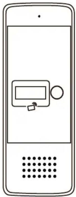
natural_image
Line drawing of a smartphone with a control panel and dotted pattern (no text or symbols)PL
ZESTAW DOMOFONOWY
EN
INTERCOM KIT
DE
GEGENSPRECHANLAGE
FR
KIT INTERPHONE
IT
KIT INTERFONO
ES
text_image
Diagram showing nine types of household appliances and accessories including a mobile phone, wall-mounted sensors, and ring rings with numbered labels.2
text_image
1 2 3 4 5 6 a b c 7 8 1 2345 5 63
text_image
1 2 3 4 5 6 7 8 9 JW1 JBJ1 S14
text_image
1.4-1.7 m5
flowchart
graph TD
    A["Device with cable and cable routing"] --> B["Device with cable and cable routing"]
    B --> C["Device with cable and cable routing"]
    style A fill:#f9f,stroke:#333
    style B fill:#bbf,stroke:#333
    style C fill:#dfd,stroke:#333
6
natural_image
Technical line drawing of a mechanical bracket with screws and cylindrical components (no text or symbols)7
flowchart
graph TD
    A["Mobile Phone 1"] --> B["Device Component"]
    B --> C["Mobile Phone 2"]
    style A fill:#f9f,stroke:#333
    style C fill:#bbf,stroke:#333
8
natural_image
Line drawings showing a hand interacting with a mobile phone and a close-up of the phone's screen (no text or symbols present)| PL | ENDEFRITES | |||||
| 1 | Skład zestawu:1. Unifon - 1 szt.2. Kaseta zewnętrzna - 1 szt.3. Daszek ochronny do kasety zewnętrznej - 1 szt.4. Śruby samogwintujące - 4 szt.5. Zasilacz sieciowy6. Kołki do montażu - 4 szt.7. Śruba zabezpieczająca8. Brelok użytkownika - 5 szt.9. Brelok administratora - 2 szt. | Set contents:1. Intercom - 1 pc.2. Outdoor station - 1 pc.3. Protective cover for the external casing - 1 pc.4. Self-tapping screws - 4 pcs.5. Power socket - 1 pc.6. Mounting pins - 4 pcs.7. Security screw - 1 pc.8. User key fob - 5 pcs.9. Administrator key fob - 2 pcs. | Lieferumfang:1. Innenstation - 1 Stk.2. Außengehäuse - 1 Stk.3. Schutzabdeckung für das Außengehäuse - 1 Stk.4. Selbstschneidende Schrauben - 4 Stk.5. Strombuchse - 1 Stk.6. Montagedübel - 4 Stk.7. Sicherheitsschraube - 1 Stk.8. Benutzer-Schlüsselanhänger - 5 Stk.9. Administrator- Schlüsselanhänger - 2 Stk. | Contenu du kit :1. Interphone - 1 pc.2. Platine extérieure - 1 pc.3. Couvercle de protection pour le boîtier externe - 1 pc.4. Vis autotaraudeuses - 4 pcs.5. Prise d'alimentation - 1 pc.6. Chevilles de montage - 4 pcs.7. Vis de sécurité - 1 pc.8. Porte-clés utilisateur - 5 pcs.9. Porte-clés administrateur - 2 pcs. | Contenuto del set:1. Citofono - 1 pz.2. Pulsantiera esterna - 1 pz.3. Copertura protettiva per la custodia esterna - 1 pz.4. Viti autofilettanti - 4 pz.5. Presa di alimentazione - 1 pz.6. Tasselli di montaggio - 4 pz.7. Vite di sicurezza - 1 pz.8. Portachiavi utente - 5 pz.9. Portachiavi amministratore - 2 pz. | Contenido del conjunto:1. Intercomunicador - 1 ud.2. Panel exterior - 1 ud.3. Cubierta protectora para la caja externa - 1 ud.4. Tornillos autorroscantes - 4 uds.5. Toma de corriente - 1 ud.6. Tacos de montaje - 4 uds.7. Tornillo de seguridad - 1 ud.8. Llavero de usuario - 5 uds.9. Llavero de administrador - 2 uds. |
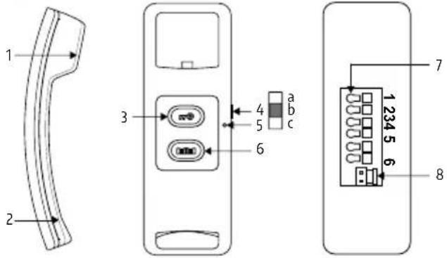
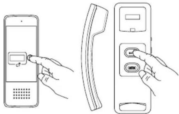
| 2 | Budowa unifonu:1. Głośnik2. Mikrofon3. Przycisk odblokowywania rygla4. Przełącznik głośności dzwonka: a. wysoki, b. średni, c. niski5. Wskaźnik LED6. Przycisk otwierania bramy7. Zaciski połączeniowe8. Gniazdo zasilania 12V DC | Handset structure:1. Speaker2. Microphone3. Door lock release button4. Call volume switch: high, medium, low5. LED indicator6. Gate opening button7. Connection terminals8. 12 V DC power socket | Aufbau des Innenhörers:1. Lautsprecher2. Mikrofon3. Türöffner-Taste4. Lautstärkeschalter: hoch, mittel, niedrig5. LED-Anzeige6. Toröffner-Taste7. Anschlussklemmen8. 12-V-DC-Strombuchse | Structure du combiné:1. Haut-parleur2. Microphone3. Bouton d'ouverture de la serrure4. Commutateur de volume: fort, moyen, faible5. Indicateur LED6. Bouton d'ouverture de portail7. Bornes de connexion8. Prise d'alimentation 12 V CC | Struttura del citofono:1. Altoparlante2. Microfono3. Pulsante di sblocco della serratura4. Interruttore del volume: alto, medio, basso5. Indicatore LED6. Pulsante di apertura cancello7. Terminali di collegamento8. Presa di alimentazione 12 V CC | Estructura del interfono:1. Altavoz2. Micrófono3. Botón de desbloqueo de cerradura4. Interruptor de volumen: alto, medio, bajo5. Indicador LED6. Botón de apertura de puerta7. Terminales de conexión8. Toma de alimentación 12 V CC |
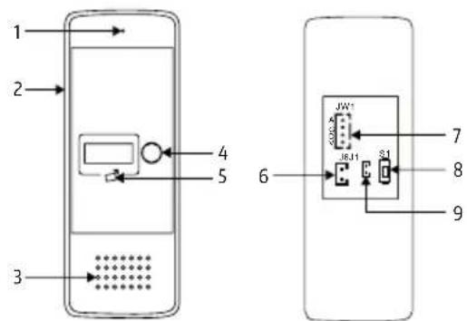
| 3 | Budowa kasety:1. Mikrofon2. Daszek ochronny3. Głośnik4. Przycisk wywołania5. Czytnik breloków zbliżeniowych6. Gniazdo rygla 12V DC (elektrozaczepu)7. Gniazdo do podłączenia unifonu8. Przycisk kodowania nowych breloków Administratora9. Gniazdo przycisku opuszczania posesji | Construction of the outdoor station:1. Microphone2. Protective cover3. Speaker4. Call button5. Key fob reader6. 12 V DC electric strike output7. Connection terminals8. Button for programming new key fobs9. Administrator session release button | Aufbau der Außen-station:1. Mikrofon2. Schutzabdeckung3. Lautsprecher4. Ruftaste5. Schlüsselanhänger-Lesegerät6. Ausgang für 12-V-DC Türöffner7. Anschlussklemmen8. Taste zur Programmierung neuer Schlüsselanhänger9. Taste zum Beenden der Administrator-Sitzung | Construction de la Platine extérieure:1. Microphone2. Couvercle de protection3. Haut-parleur4. Bouton d'appel5. Lecteur de porte-clés6. Sortie pour gache électrique 12 V CC7. Bornes de connexion8. Bouton de programmation de nouveaux porte-clés9. Bouton de fin de session administrateur | Struttura della Pulsantiera esterna:1. Microfono2. Copertura protettiva3. Altoparlante4. Pulsante di chiamata5. Lettore di portachiavi6. Uscita per serratura elettrica 12 V CC7. Terminali di collegamento8. Pulsante di programmazione di nuovi portachiavi9. Pulsante di rilascio sessione amministratore | Estructura de la Panel exterior:1. Micrófono2. Cubierta protectora3. Altavoz4. Botón de llamada5. Lector de llaveros6. Salida para cerradura eléctrica de 12 V CC7. Terminales de conexión8. Botón para programar nuevos llaveros9. Botón de finalización de sesión de administrador |
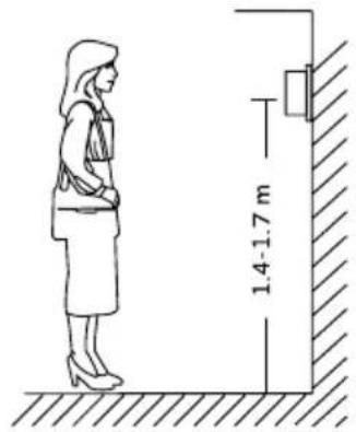
| 4 | Właściwie umiejscowienie kasety zewnętrznej | Proper placement of the outdoor station | Richtige Platzierung des Außengehäuses | Placement correct du platine extérieure | Posizionamento corretto della pulsantiera esterna | Colocación correcta de la panel exterior |
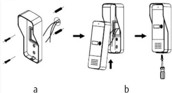
| 5a | Montaż daszku ochronnego | Montage der Schutzabdeckung | Installation du couvercle de protection | Installation du couvercle de protection | Installazione della copertura protettiva | Instalación de la cubierta protectora |
| 5b | Montaż kasety w daszku ochronnym | Installation of the casing in the protective cover | Montage des Gehäuses in der Schutzabdeckung | Installation du boîtier dans le couvercle de protection | Installazione della cassetta nella copertura protettiva | Instalación de la caja en la cubierta protectora |
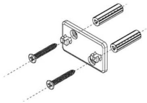
| 6 | Instalacja ramki montażo-wej unifonu | Installation of the protective frame in the recess | Installation des Schutzrahmens in der Nische | Installation du cadre de protection dans la niche | Installazione del telaio protettivo nella nicchia | Instalación del marco protector en el hueco |
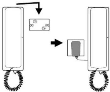
| 7 | Montaż unifonu na ścianie | Installation of the handset on the wall | Montage des Innenhörers an der Wand | Installation du combiné au mur | Installazione del citofono a parete | Instalación del Intercomunicadores de Audio |
| 8 | Prowadzenie rozmowy Conducting a conversation Gesprächsführung Conduite d'une conversation | Conduzione della conversazione | Realización de una conversación | |||
II. SCHEMATY INSTALACYJNE / INSTALLATION DIAGRAMS / INSTALLATIONSSCHEMAS / SCHÉMAS D'INSTALLATION / SCHEMI DI INSTALLAZIONE / ESQUEMAS DE INSTALACIÓN
A
flowchart
graph TD
    A["1"] --> B["2"]
    B --> C["JW1"]
    C --> D["S1"]
    D --> E["123456"]
    E --> F["7"]
    F --> G["6"]
    H["4"] --> I["N.O."]
    I --> J["3"]
    J --> K["2"]
    L["8"] --> M["4"]
    N["1"] --> O["*"]
    P["1"] --> Q["*"]
    R["1"] --> S["*"]
B1
flowchart
graph TD
    A["123456"] -->|N.O.| B["Switch"]
    C["2"] -->|*| B
    D["3"] -->|*| B
B2
text_image
1 123456 2 3 *C
text_image
1 2 3 4 5 6D
text_image
JW1 A G D V J6 J1 S1| PL | ENDEFRITES | |||||
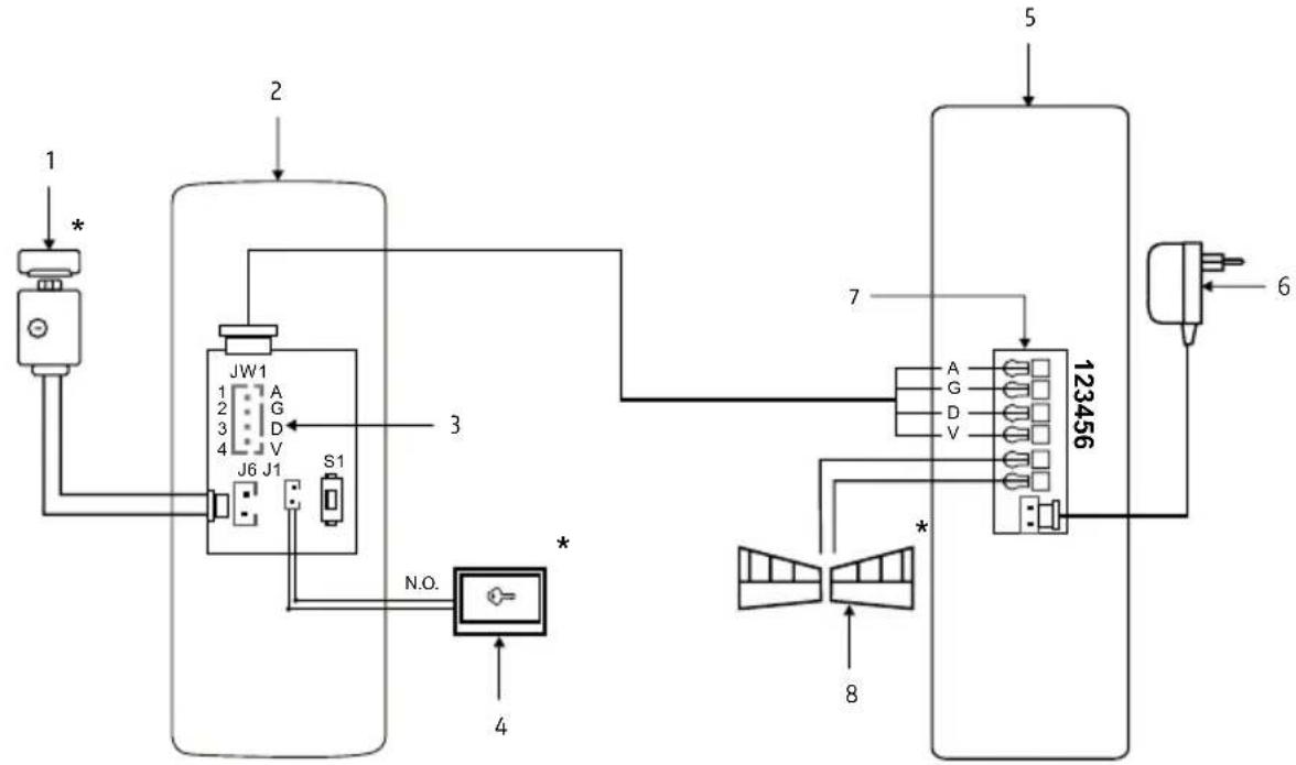
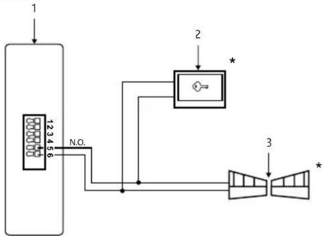
| A | Schemat połączeń zestawu:1. Rygiel/ Elektrozaczep2. Kaseta zewnętrzna3. Gniazdo 4 pinowe:1. AUDIO (Niebieski)2. GND (Czarny)3. DATA (Zielony)4. VCC (Brązowy)4. Przycisk opuszczania posesji5. Unifon6. Zasilacz7. Magistrala zaciskowa8. Automat bramy | Wiring diagram of the set:1. Lock/ Electric strike2. Outdoor station3. 4-pin socket:1. AUDIO (Blue)2. GND (Black)3. DATA (Green)4. VCC (Brown)4. Gate exit button5. Intercom6. Power supply7. Terminal block8. Gate operator | Schaltplan des Sets:1. Schloss / Elektro-Türöffner2. Außenstation3. 4-polige Buchse:1. AUDIO (Blau)2. GND (Schwarz)3. DATA (Grün)4. VCC (Braun)4. Toröffnungs-Taster5. Innenstation6. Netzteil7. Klemmenblock8. Torantrieb | Schéma de câblage du kit :1. Pêne/ Serrure électrique2. Platine extérieure3. Prise 4 broches :1. AUDIO (Bleu)2. GND (Noir)3. DATA (Vert)4. VCC (Marron)4. Bouton de sortie du terrain5. Interphone6. Alimentation électrique7. Bloc de terminaison8. Moteur de porte | Schema di collegamento del kit:1. Catenaccio/ Serratura elettrica2. Pulsantiera esterna3. Presa a 4 pin:1. AUDIO (Blu)2. GND (Nero)3. DATA (Verde)4. VCC (Marrone)4. Pulsante di uscita dalla proprietà5. Interfono6. Alimentatore7. Barra di morsetti8. Motorino del cancello | Diagrama de conexiones del conjunto:1. Cerradura / Cerradura eléctrica2. Panel exterior3. Conector de 4 pines:1. AUDIO (Azul)2. GND (Negro)3. DATA (Verde)4. VCC (Marrón)4. Botón de salida de la propiedad5. Intercomunicador6. Fuente de alimentación7. Bloque de terminales8. Motor de puerta |
| B1 | Podłączenie automatu bramy wjazdowej lub garażowej:1. Unifon2. Przycisk otwierania bramy3. Automat bramy/ Napęd bramy | Connection of the driveway or garage gate operator:1. Intercom2. Gate opening button3. Gate operator/ Gate drive | Anschluss des Einfahrtoder Garagentorantriebs:1. Gegensprechanlage2. Toröffnungs-Taster3. Torantrieb/Torantriebseinheit | Connexion de l'automatisme de porte d'entrée ou de garage :1. Interphone2. Bouton d'ouverture de la porte3. Moteur de porte/Moteur de portail | Collegamento dell'automazione del cancello d'ingresso o del garage:1. Citofono2. Pulsante di apertura del cancello3. Motorino del cancello/Azionamento del cancello | Conexión del automatismo de puerta de entrada o garaje:1.Intercomunicador2. Botón de apertura de la puerta3. Motor de puerta/Motor de portón |
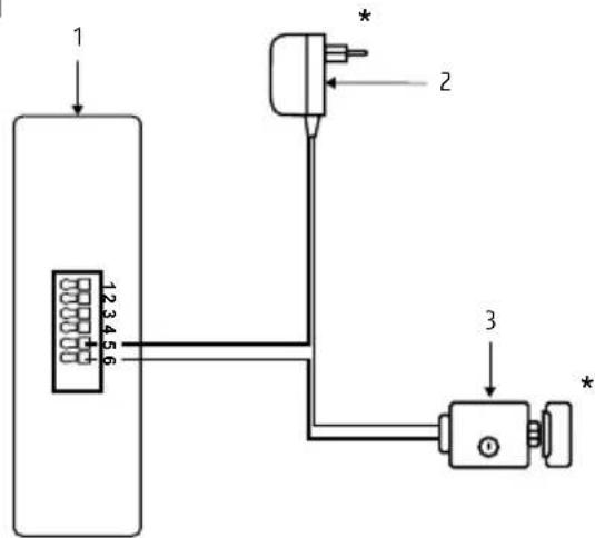
| B2 | Podłączenie odatkowego rygla (otwieranie dodatkowej furtki lub drzwi):1. Unifon2. Zasilacz rygla/ elektrozaczepu3. Rygiel/ Elektrozaczep | Connection of an additional bolt (opening an additional gate or door):1. Intercom2. Power supply for the bolt/ electric strike3. Bolt/ Electric strike | Anschluss eines zusätzlichen Riegels (Öffnen eines zusätzlichen Tors oder einer Tür):1. Gegensprechanlage2. Netzteil für den Riegel/ Elektroschloss3. Riegel/ Elektroschloss | Connexion d'un verrou supplémentaire (ouverture d'une porte ou d'un portail supplémentaire) :1. Interphone2. Alimentation pour le verrou/ serrure électrique3. Verrou/ Serrure électrique | Collegamento di un chiavistello aggiuntivo (apertura di un cancello o porta aggiuntiva):1. Citofono2. Alimentatore per il chiavistello/ serratura elettrica3. Chiavistello/ Serratura elettrica | Conexión de un cerrojo adicional (apertura de una puerta o portón adicional):1. Intercomunicador2. Fuente de alimentación para el cerrojo/ electroimán3. Cerrojo/ Electroimán |
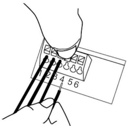
| C | Podłączenie przewodów do magistrali zaciskowej | Connection of wires to the terminal block | Anschluss der Drähte an die Klemmleiste | Connexion des fils au bloc de bornes | Collegamento dei fili alla barra di morsetti | Conexión de los cables a la barra de terminales |
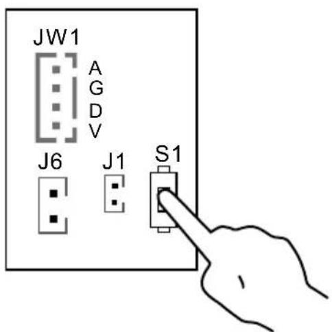
| D | Przycisk programowania S1 | Programming button S1Programmiertaste S1 | Bouton de programmation S1 | Pulsante di programmazione S1 | Botón de programación S1 | |
| * | Dodatkowy element wyposażenia | Additional equipment | Element der Zusatzausstattung | Équipement supplémentaire | Accessorio aggiuntivo Equipamiento adicional | |
PL
1. OGÓLNE ZASADY BEZPIECZNEGO UŻYTKOWANIA PRODUKTU
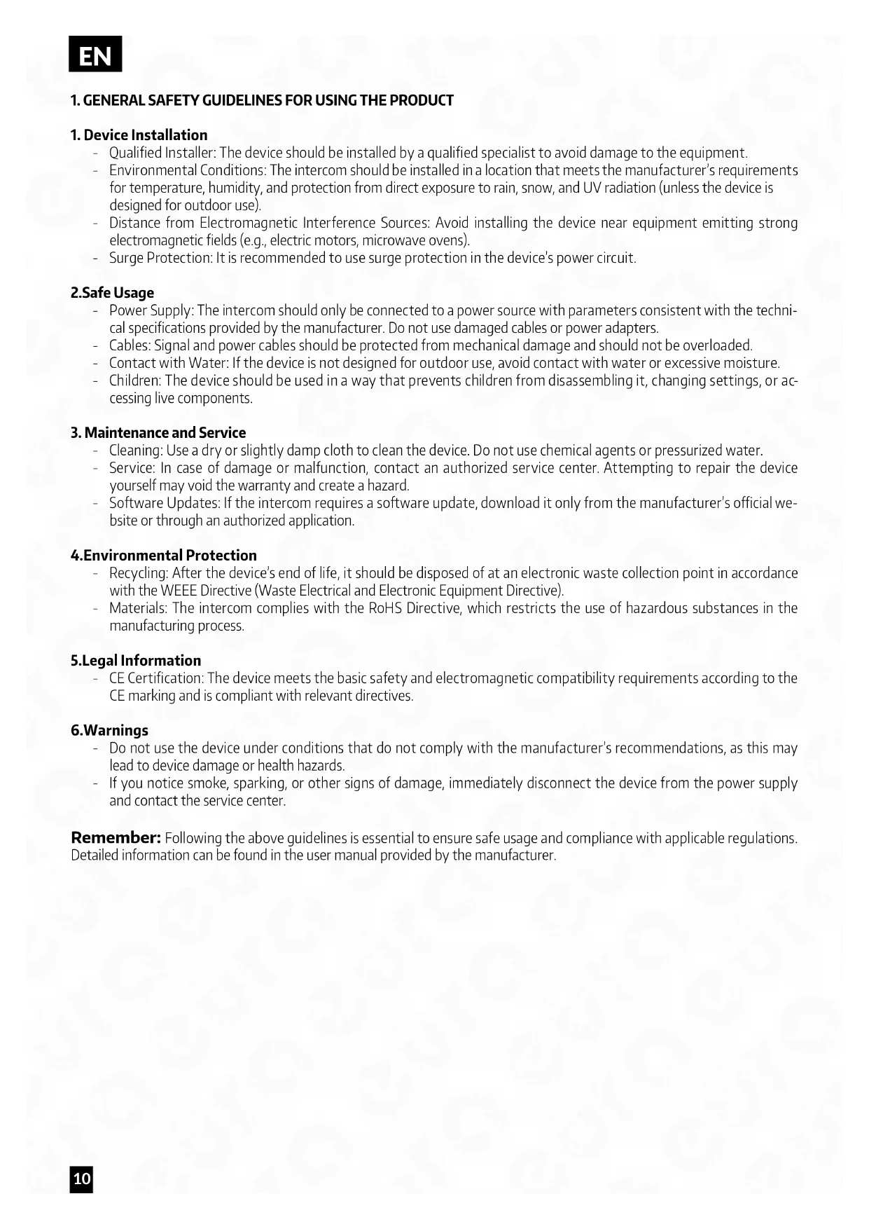
1. GENERAL SAFETY GUIDELINES FOR USING THE PRODUCT
1. Device Installation
- Qualified Installer: The device should be installed by a qualified specialist to avoid damage to the equipment.
- Environmental Conditions: The intercom should be installed in a location that meets the manufacturer's requirements for temperature, humidity, and protection from direct exposure to rain, snow, and UV radiation (unless the device is designed for outdoor use).
- Distance from Electromagnetic Interference Sources: Avoid installing the device near equipment emitting strong electromagnetic fields (e.g., electric motors, microwave ovens).
- Surge Protection: It is recommended to use surge protection in the device's power circuit.
2.Safe Usage
- Power Supply: The intercom should only be connected to a power source with parameters consistent with the technical specifications provided by the manufacturer. Do not use damaged cables or power adapters.
- Cables: Signal and power cables should be protected from mechanical damage and should not be overloaded.
- Contact with Water: If the device is not designed for outdoor use, avoid contact with water or excessive moisture.
- Children: The device should be used in a way that prevents children from disassembling it, changing settings, or accessing live components.
3. Maintenance and Service
- Cleaning: Use a dry or slightly damp cloth to clean the device. Do not use chemical agents or pressurized water.
- Service: In case of damage or malfunction, contact an authorized service center. Attempting to repair the device yourself may void the warranty and create a hazard.
- Software Updates: If the intercom requires a software update, download it only from the manufacturer's official website or through an authorized application.
4.Environmental Protection
- Recycling: After the device's end of life, it should be disposed of at an electronic waste collection point in accordance with the WEEE Directive (Waste Electrical and Electronic Equipment Directive).
- Materials: The intercom complies with the RoHS Directive, which restricts the use of hazardous substances in the manufacturing process.
5. Legal Information
- CE Certification: The device meets the basic safety and electromagnetic compatibility requirements according to the CE marking and is compliant with relevant directives.
6.Warnings
- Do not use the device under conditions that do not comply with the manufacturer's recommendations, as this may lead to device damage or health hazards.
- If you notice smoke, sparking, or other signs of damage, immediately disconnect the device from the power supply and contact the service center.
Remember: Following the above guidelines is essential to ensure safe usage and compliance with applicable regulations. Detailed information can be found in the user manual provided by the manufacturer.
2. INSTALLATION OF THE KIT
2.1. INSTALLATION OF THE PHONE
ATTENTION!
The standard installation height of the phone after mounting is approximately 145 cm, however, its position can be adjusted to meet the individual needs of the users.
- In the selected location on the wall, mark the positions for the mounting plugs by using the two holes in the mounting frame (Fig. 6).
- Drill two mounting holes ∅ 6mm at the marked positions and insert the mounting plugs.
- Using two screws, attach the module's mounting frame to the wall (Fig. 6) in a way that ensures easy and aesthetically pleasing cable routing for the connection and power supply wires.
- Connect the individual wires of the cable to the terminal bus clamps (Fig. C) on the back of the module according to the wiring diagram (Fig. A).
- Connect the handset to the handset socket.
- Connect the power supply to the power socket.
- On the back of the module housing, there are two holes for hanging it on the mounting frame. Carefully hang the module so that the two brackets on the frame align with the housing holes (Fig. 7).
- Finally, plug the power supply into the \~230 V/50Hz mains.
- Check that all connections are secure and that the device operates correctly after being powered on.
How to connect wires to the terminal block:
- Press the button and insert the wire into the appropriate hole (Fig. C).
- Release the button to clamp the wire in place.
- Gently pull the wire to ensure it is securely clamped.
Additional information:
Cable connecting the internal and external units:
• Distance 0 - 30m: 4×0.5 mm ^2
• Distance 30 - 50m: 4×1.0 mm²
The J6 socket on the external unit is used for connecting the lock. When connecting the lock, use a 2×1.0 mm² cable, and the cable length should not exceed 10m. Terminals 5/6 in the intercom are used to connect, for example, the gate drive.
2.2. INSTALLATION OF THE OUTDOOR STATION
The outdoor module is factory pre-configured for surface mounting.
ATTENTION!
The correct location of the external module determines the comfort of working with the device. It is recommended to experimentally select the mounting location before making the mounting hole. The standard installation height of the external cassette is from 140 to 170 cm.
Mounting procedure:
- Unscrew the bottom mounting screw and separate the external panel from the protective cover.
- In the chosen location on the wall/post, mark the spots for the mounting plugs on the wall through the 2 holes in the bottom of the protective cover (see Fig. 5a).
- Drill 2 mounting holes ∅ 6mm in the marked locations, and then insert the mounting plugs.
- Using 2 mounting screws, attach the protective cover of the external panel to the wall.
- Connect the 4 wires running to the internal module (intercom) to the cassette module according to the diagram shown in (Fig. A).
- Connect the 2 wires leading to the electromagnetic lock (additional equipment) to the cassette module according to diagram A.
- Place the external panel into the previously mounted protective cover on the wall using the hole for securing the cover, and screw in the bottom mounting screw (see Fig. 5b).
* For mounting the outdoor station, it is recommended to use the screws provided in the kit. Using screws longer than those provided in the kit may cause permanent damage to the mainboard.
ATTENTION!
- Do not make any connections or switch wires while the device is connected to the \~230V power supply. Failure to follow this recommendation may result in device damage. Before installation or disassembly, disconnect the power supply from the mains.
- Damage caused by water ingress into the module is not covered by the warranty.
EN
3. CONDUCTING A CONVERSATION
When the person at the entrance presses the button on the external panel, the gong signal is activated in the internal module (intercom). After picking up the handset of the internal module, a conversation can be conducted with the person at the entrance. The person inside the room has the ability to remotely open the gate by pressing the electromagnetic lock release button ☐@the intercom and to open the gate ((second gate, door, etc.) by pressing the gate opening button.
ATTENTION!
During intercom standby mode, if the handset is lifted, it will be possible to conduct a conversation, release the lock, and open the gate.
4. PROGRAMMING
4.1. ADDING USER REMOTE CONTROL KEYS
ATTENTION!
The remote control keys included in the set are pre-programmed from the factory.
The device allows the addition of user key fobs, which, when brought close to the reader, will release the lock. The set includes two administrator key fobs: the add key fob (Add Card) and the delete key fob (Delete Card), as well as 5 user key fobs. To add a user key fob, in the standard operating mode of the device, swipe the add key fob (Add Card) in front of the reader until an acoustic signal appears. Then, swipe the new user key fob in front of the reader, and finally, swipe the add key fob (Add Card) again — an acoustic signal will confirm the successful addition of the key fob.
4.2. REMOVING USER KEY FOBS
To remove a user key fob, in the standard operating mode of the device, swipe the delete key fob (Delete Card) in front of the reader until an acoustic signal appears. Then, swipe the user key fob you want to remove from memory in front of the reader, and finally, swipe the delete key fob (Delete Card) again — the appearance of an acoustic signal will confirm the successful removal of the key fob.
4.3. INITIALIZING NEW ADMINISTRATOR KEY FOBS
Press and hold the S1 button for 3 seconds, then release the button after hearing 3 short tones and 1 long tone. Next, swipe 2 key fobs, the first one will be set as the add key fob (Add Card) and the second one as the delete key fob (Delete Card). After programming, the external unit will automatically return to normal operation mode. The process of adding new administrator key fobs is complete.
5. OPENING THE GATE OR ADDITIONAL ENTRY
In addition to remotely opening the entrance gate or door, the intercom also offers the ability to control a second entry, such as a driveway gate opener, garage door opener, lock at a second gate, or door, etc. To control the second entry, use the 5 and 6 terminals at the back of the intercom housing. Terminals 5 and 6 serve as a N.O. (normally open) relay output, so for proper operation, the gate opener should also allow triggering by briefly shorting the input terminals (N.O.). In this case, simply connect terminals 5 and 6 at the intercom output, for example, in parallel with a push button inside the premises used to manually operate the gate opener (see diagram B1). It is also possible to connect a standard electromagnetic lock to terminals 5 and 6, for example, to open a second gate to the premises. In this case, the lock must be powered by a separate power supply with parameters (voltage and current rating) appropriate for the lock's specifications (see diagram B2).
6. SOUND SIGNALS
Valid card—1 short signal
Invalid card—2-short signals
Entering/exiting the card adding mode—long signal
Entering/exiting the card deletion mode-1 long signal
Successful user card addition-1 short signal
Unsuccessful user card addition—1 short signal
Duplicated card number 2 short signals
ntering administrator card adding mode—3 short signals and 1 long
CCLEANING AND MAINTENANCE OF INDIVIDUAL COMPONENTS OF THE SET
In case of dirt on individual parts of the set, clean them only with a soft, slightly damp cloth with a small amount of cleaning agents designed for cleaning plastic parts.
ATTENTION!
The use of cleaning agents based on solvents, gasoline, etc., and products containing abrasive substances is prohibited!
- TECHNICAL SPECIFICATION OF THE KIT
| SET | |
| Power supply voltage 12 V DC | |
| Power consumption - standby / operation <1,5W / <6,5W | |
| Number of connecting wires 4 | |
| Number of supported outputs 2 | |
| OUTDOOR STATION | |
| Number of supported premises 1 | |
| Number of supported outputs 1 | |
| Types of outputs Output 1: 12V DC 350mA | |
| Lock activation time Output 1: 5 seconds | |
| Housing material Aluminum alloy | |
| Mounting method Surface mounting | |
| Protective cover Yes | |
| Proximity keyfob reader Yes | |
| Maximum radiation power | <5mW |
| Operating frequency | 125kHz (UNIQUE) |
| Protection rating | IP65 |
| Permissible relative humidity | 10%...90% RH |
| Operating temperature range of the outdoor station | -20°C ~ +50°C |
| External cassette dimensions (H x W x D) | 170 x 65 x 39 mm |
| Net weight of the outdoor station | 330 g |
| INTERCOM | |
| Number of gong melodies | 1 |
| Number of outputs supported | 1 |
| Types of outputs Output 2: N.O. max 1A/ 24V DC | |
| Activation time of output | Output 2: 1 second |
| Protection rating | IP20 |
| Permissible relative humidity | 10%...90% RH |
| Operating temperature range of the intercom | -10°C ~ +55°C |
| Intercom dimensions (H x W x D) | 210 x 67 x 56 mm |
| Net weight of the intercom | 260 g |
*the manufacturer reserves the right to make changes to technical parameters without prior noticea
Carte valide—signal court
As the only distributor of the Eura products, Eura-Tech is obliged to ensure efficient warranty and post-warranty service. In the countries where Eura-Tech has neither its own service network, nor DOOR-TO-DOOR service, the quality claims are dealt with by authorised distributors of the Eura products on the basis of the signed distribution agreements. Within the framework of such agreements, Eura-Tech will ensure financing of the possible repairs and delivery of spare parts.