SD-13A2 - Gas detector Eura - Free user manual and instructions
Find the device manual for free SD-13A2 Eura in PDF.


User questions about SD-13A2 Eura
0 question about this device. Answer the ones you know or ask your own.
Ask a new question about this device
Download the instructions for your Gas detector in PDF format for free! Find your manual SD-13A2 - Eura and take your electronic device back in hand. On this page are published all the documents necessary for the use of your device. SD-13A2 by Eura.
USER MANUAL SD-13A2 Eura
natural_image
Color calibration bar with grayscale and color swatches, no text or symbols presenteura
SD-13A2
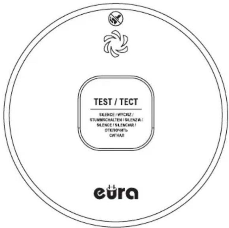
text_image
TEST / TECT SILENCE / WYCRZ / STUMMSCHALTEN / SILENZA / SILENCE / SILENCIAR / OTKENDCHIEB CHINAI euraPL CZUJNIK DYMU
EN SMOKE DETECTOR
DE RAUCHMELDER
FR DÉTECTEUR DE FUMÉE
IT RILEVATORE DI FUMO
ES DETECTOR DE HUMO
RU ДАТЧИК ДЫМА

natural_image
Color palette bar with grayscale swatches and a central crosshair symbol (no text or labels)PL CZUJNIK DYMU 3
EN SMOKE DETECTOR....10
DE RAUCHMELDER 17
FR DÉTECTEUR DE FUMÉE...... 24
IT RILEVATORE DI FUMO 31
ES DETECTOR DE HUMO 38
RU ДАТЧИК ДЫМА...... 45


1. OGÓLNE ZASADY BEZPIECZNEGO UŻYTKOWANIA PRODUKTU
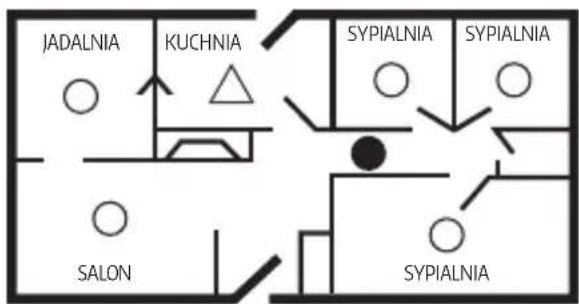
PLAN JEDNOKONDYGNACYJNY
text_image
JADALNIA KUCHNIA SYPIALNIA SYPIALNIA SALON SYPIALNIA
- Before installation, connection, and use of the device, please read this user manual carefully. If you have any difficulty understanding its contents, please consult the seller of the device.
- Self-installation and activation of the device is possible provided that appropriate tools are used. Nevertheless, it is recommended that installation is carried out by qualified personnel.
- The manufacturer is not responsible for damage resulting from improper installation or tampering with the device, including self-made repairs or modifications.
- The detector is designed exclusively for smoke detection and is not intended to detect carbon monoxide, methane, or any other gases, nor does it replace an alarm system or fire extinguishing system.
- This device is not a substitute for proper installation or maintenance of fuel-burning appliances, nor for appropriate ventilation systems and exhaust systems.
• The detector is intended for indoor use only, and for domestic use exclusively.
2. SAFETY NOTES FOR USING THE DEVICE WITH A BUILT-IN BATTERY
- Avoid high temperatures – do not expose the device to high temperatures (e.g., direct sunlight, heaters), as this may lead to overheating and battery damage.
- Do not expose to moisture – avoid contact with water and excessive humidity to prevent short circuits and battery corrosion.
- Do not tamper with the battery – do not disassemble, puncture, or crush the battery, as this may result in chemical leakage or explosion.
- Store under proper conditions – if not used for an extended period, store the device in a cool, dry place.
- Do not use a damaged device – if you notice a swollen battery, overheating, or any malfunction, stop using the device immediately and contact support.
- Dispose of in accordance with regulations – do not discard the device in regular trash, but bring it to an appropriate recycling facility.
3. PRECAUTIONS AND MAINTENANCE
- Do not allow the air inlets on the device housing to become blocked with dust or dirt.
- Do not install the device in areas with high humidity, dust, or temperatures outside the acceptable operating range.
- Do not paint the device. If painting the room where the detector is installed, first remove the device from the wall, and reinstall it after the paint dries.
- Do not install the device near windows, doors, or ventilation ducts.
- At least once a week, test the detector using the test button on the device housing.
- When cleaning the device, turn it off. Do not use liquids – use a soft brush or vacuum cleaner.
• Clean air inlets regularly (e.g., once a month).
• Do not open the housing or attempt to repair the device yourself. - Transport and store the device in its original packaging. Avoid mechanical damage (do not drop the package).
• Not following the above instructions may reduce the life of the device. - Replace the device with a new one 10 years after the production date.
4. DEVICE CHARACTERISTICS
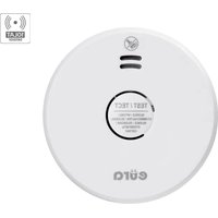
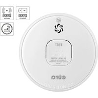
The device is intended for monitoring enclosed spaces for the presence of smoke and for issuing an alarm in the event of a fire hazard. It is equipped with a high-quality photo-optical sensor. It is mounted on the ceilings of protected rooms. In the event of a threat (smoke), the sensor activates immediately:
- Acoustic alarm – sound from the speaker at approximately 85 dB,
- Optical alarm – LED indicator located on the front of the device housing.
The device has a test button to verify proper operation. The detector also features a system that checks the battery charge level.
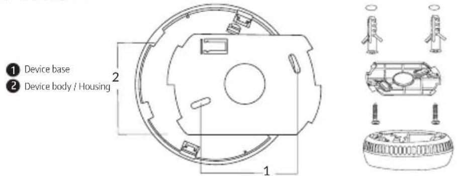
5. DEVICE STRUCTURE
text_image
① Device base ② Device body / HousingFig. 1
5.1. INSTALLATION
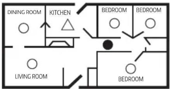
The smoke detector should be installed in every room (except bathrooms and kitchens) and in other parts of the house to ensure that all household members can hear and respond to the alarm. For minimum protection, a detector should be installed in the hallway between the living area and the bedrooms. The device should be located as close as possible to living spaces, and the alarm sound must be audible in the bedrooms.
SINGLE-STORY PLAN
text_image
DINING ROOM KITCHEN BEDROOM BEDROOM LIVING ROOM BEDROOM
Smoke detectors for minimal protection

Smoke detectors for additional protection

Ionization smoke detector with hush feature or photoelectric type
MULTI-STORY PLAN

text_image
HALLWAY BEDROOM BEDROOM LIVING ROOM KITCHEN BASEMENT ENTRANCEFig. 2
EN
5.2. ACTIVATING THE DETECTOR
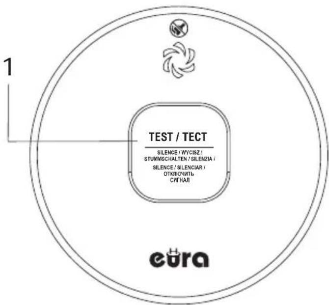
Press and hold the test button for about 3 seconds until the LED indicator lights up, then immediately release the button. The smoke detector will emit a sound signal, indicating activation.
WARNING! If no sound is generated, it means the smoke detector has not been properly activated and should not be used! The device cannot be deactivated!
5.3. TESTING AFTER ACTIVATION
Immediately after activation, a test must be performed. Test the device to ensure it is functioning correctly by pressing the test button for at least 5 seconds. If the electronic system, siren, and battery are working properly, the alarm will sound.
WARNING! Do not use an open flame to test the alarm – this may damage the device, ignite flammable materials, and cause a fire.
CAUTION! Due to the 85 dB alarm volume, always maintain an arm's length distance during testing.

text_image
TEST / TECT SILENCE / WYCISZ / STUNMSCHALTEN / SILENZIA / SILENCE / SILENCIAR / OTKLIOWCHITY CINHAJI eura1 Test button
Fig. 3
12


text_image
Color calibration bar with grayscale and color-coded sections, a crosshair symbol, and a 'EN' label at the bottom right.5.4. CHOOSING THE INSTALLATION LOCATION
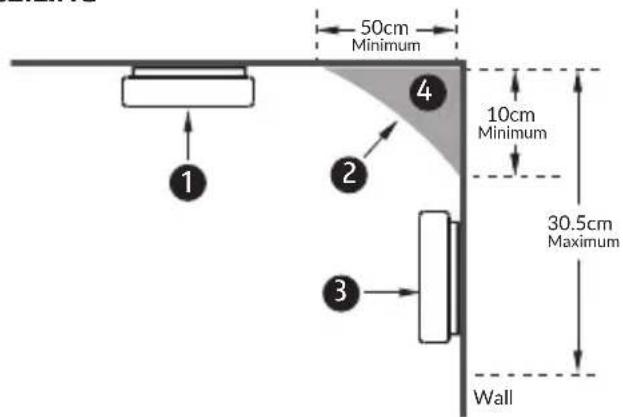
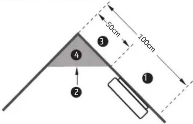
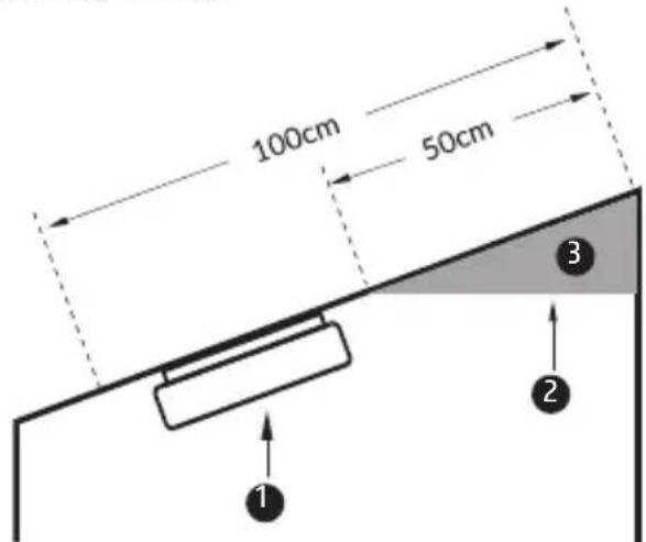
Select the installation location on the ceiling/wall in accordance with the instructions in Figures 4–6.
CEILING
text_image
50cm Minimum 1 2 3 4 10cm Minimum 30.5cm Maximum Wall1 Recommended installation area
2 Do not install the sensor in this location
3 Acceptable installation area on the wall
4 Dead zone
Fig. 4
TRIANGULAR CEILING
text_image
50cm 100cm ① ② ③ ④1 Installation area
② Do not install the sensor in this location
3 Do not install in this area
4 Dead zone
Fig. 5
SLOPED CEILING
text_image
100cm 50cm ① ② ③1 Recommended installation location
2 Do not install the sensor in this location
3 Dead zone
Fig. 6
EN
Warning!
- If it's not possible to install the smoke detector on the ceiling, wall mounting is acceptable. However, the optimal location for a smoke detector is the ceiling.
- A dead air space is an area present in every room. Due to lack of air circulation, or if the circulation is too weak or too strong (e.g., near air vents), the detector should not be installed in a dead air space.
5.5. DEVICE INSTALLATION
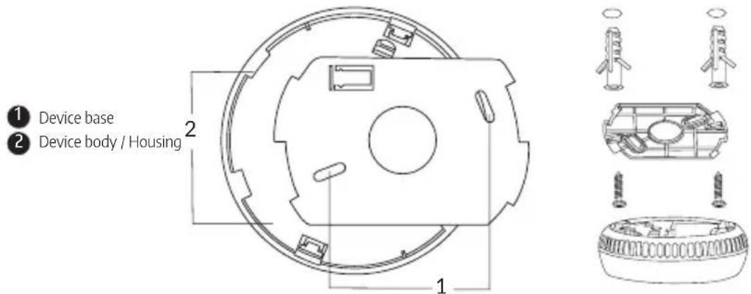
To install the device, mount its base to the ceiling. To do this, determine the mounting location, drill holes for the wall plugs, and attach the base using the screws provided in the set. Next, attach the device body to the base by inserting the two distinctive clips located on the edge of the base (fig. 7) into the two elongated slots on the body of the device (fig. 7). The final step is to rotate the body clockwise.
text_image
① Device base ② Device body / Housing 1 2Fig. 7
6. OPERATION PRINCIPLE
6.1. Normal Operation:
When the device operates correctly, the red LED blinks once every 40 seconds, indicating the detector is functioning properly.
6.2. Battery Failure or Low Battery Level:
The device emits an intermittent sound signal, and the LED blinks once every 40 seconds - the device must be replaced.
6.3. Device Malfunction:
A 16-second sound signal that repeats every 40 seconds, and the red LED blinks once.
6.4. Silencing the Alarm:
After pressing the test button for approx. 5 seconds in alarm mode, the signal is turned off, and the red LED blinks once every 8 seconds for approx. 10 minutes.
6.5. Alarm and Test Mode:
After pressing the test button in standby mode or upon detecting smoke particles, the smoke detectorentersalarmmode(continuous,pulsingsound),andtheredLEDblinksoncepersecond. The blinking LED and alarm sound will persist until the air is cleared or the test button is released.
Warning:
Minimizing False Alarms:
Smoke detectors are designed to reduce false alarms. Particles generated during cooking can trigger the alarm, especially if the detector is installed near the kitchen area. A large amount of combustion particles can be produced by spilled substances or cooking/grilling. Using a kitchen hood with external ventilation (non-recirculating type) can help remove these particles from the kitchen. The silence function (test button) is especially useful in kitchens or other areas prone to false alarms.
Guidelines for Using the Silence Function:
- The silence function should be used only when the source of smoke is known, e.g., smoke generated during grilling, ensuring the situation is safe.
- If smoke particles are still present in the air after 10 minutes, the alarm will be reactivated. You can re-enable the silence mode until the air is clean.
- The silence function can be activated multiple times until the air is free from the particles triggering the alarm.

7. DEVICE TESTING
- Test the alarm weekly to ensure it is working correctly.
- Press and hold the test button for at least 5 seconds. If the electronics, siren, and battery are working properly, the alarm will emit a sound. If there is no sound, the battery may be discharged, or there is another issue.
- Do not use an open flame to test the alarm. This could damage the device or ignite flammable materials, potentially causing a fire.
Warning: Due to the volume of the alarm (85 decibels), always stand at arm's length from the device during testing.
EN
8. SAFETY IN CASE OF DETECTED THREAT
a. Do not panic; stay calm.
b. Make sure small children and elderly individuals in the home have been alerted.
c. Leave the building as quickly as possible. Do not stop to get dressed or collect valuables — YOU DON'T HAVE TIME!
d. Before opening interior doors, check for smoke around them and feel the door with the back of your hand. If the door is hot, use an alternative exit. If you think it's safe, open the door slowly and be ready to close it immediately if smoke or heat enters.
e. If you must go through smoke to reach the exit, crawl low along the floor under the smoke, where the air is cleaner.
f. Meet at a pre-designated meeting point outside the building.
g. Call the fire department from outside the building.
h. Do not return to a burning building. Wait for the fire department to arrive. Note: These guidelines may be helpful in the event of a fire. However, to reduce the risk of a fire occurring, it is essential to follow fire safety practices and avoid hazardous situations.
9. TECHNICAL SPECIFICATION
| Power supply voltage 3 V DC | |
| Built-in battery lifespan 10 years | |
| Sensor type Photoelectric | |
| Type of detected hazard Smoke | |
| Compliance with standards EN 14604:2005, EN 14604:2005/AC:2008 | |
| Sensor lifespan 10 years | |
| Detector current consumption - standby / alarm < 15 μA / 25 mA | |
| Recommended installation location Ceilings, indoors | |
| Maximum sound level | 85 dB @ 3 m |
| Detection coverage | Approx. 20–25 m^2 |
| Protection rating IP20 | |
| Low battery warning | Yes |
| Fault signal | Yes |
| Operating temperature range | 0°C ~ +40°C |
| Operating humidity range | ≤ 93% RH |
| Detector dimensions (∅ x H) | ∅100*33.6 mm |
| Net weight of detector | 90 g |
Eura-Tech Sp. z o.o. reserves the right to change technical parameters and modify the manual without prior notice. The most up-to-date version of the manual is available on the website: www.eura-tech.eu on the specific product page.
natural_image
Technical line drawing of a mechanical component with circular features and a numbered callout (no text or symbols)natural_image
Technical line drawing of a mechanical assembly with exploded and assembled views (no text or symbols)6. FUNKTIONSWEISE
6.1. Normalbetrieb:
text_image
Color calibration bar with grayscale scale and a 'IT' label, likely from a software interface or test.natural_image
Color palette bar with grayscale shades and a central crosshair symbol (no text or labels)5.4. SCELTA DEL LUOGO DI INSTALLAZIONE
text_image
Color calibration bar with grayscale scale and a 'IT' label, likely from a software interface or test.- SPECIFICHE TECNICHE
text_image
Color calibration bar with grayscale scale and color swatches, plus a 'ES' label in the bottom right corner.text_image
50cm Minimum 1 2 4 10cm Minimum 30.5cm Maximum Parednatural_image
Technical line drawing of a mechanical component with circular features and mounting holes (no text or symbols)As the only distributor of the Eura products, Eura-Tech is obliged to ensure efficient warranty and post-warranty service. In the countries where Eura-Tech has neither its own service network, nor DOOR-TO-DOOR service, the quality claims are dealt with by authorised distributors of the Eura products on the basis of the signed distribution agreements. Within the framework of such agreements, Eura-Tech will ensure financing of the possible repairs and delivery of spare parts.
DE
GARANTIEKARTE
natural_image
Color palette bar with grayscale swatches and a central crosshair symbol (no text or labels)

05/2025
Eura-Tech Sp. z o.o.
ul. Przemysłowa 35A
84-200 Wejherowo
Poland
www.eura-tech.eu