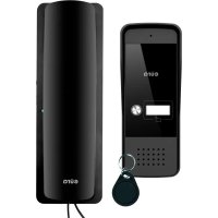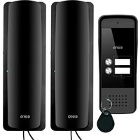
ADP-26A3 - Intercom Eura - Free user manual and instructions
Find the device manual for free ADP-26A3 Eura in PDF.


User questions about ADP-26A3 Eura
0 question about this device. Answer the ones you know or ask your own.
Ask a new question about this device
Download the instructions for your Intercom in PDF format for free! Find your manual ADP-26A3 - Eura and take your electronic device back in hand. On this page are published all the documents necessary for the use of your device. ADP-26A3 by Eura.
USER MANUAL ADP-26A3 Eura
1. GENERAL SAFETY GUIDELINES FOR USING THE PRODUCT
1. Device Installation
- Qualified Installer: The device should be installed by a qualified specialist to avoid damage to the equipment.
Environmental Conditions: The intercom should be installed in a location that meets the manufacturer's requirements for temperature, humidity, and protection from direct exposure to rain, snow, and UV radiation (unless the device is designed for outdoor use). - Distance from Electromagnetic Interference Sources: Avoid installing the device near equipment emitting strong electromagnetic fields (e.g., electric motors, microwave ovens).
- Surge Protection: It is recommended to use surge protection in the device's power circuit.
2.Safe Usage
- Power Supply: The intercom should only be connected to a power source with parameters consistent with the technical specifications provided by the manufacturer. Do not use damaged cables or power adapters.
- Cables: Signal and power cables should be protected from mechanical damage and should not be overloaded.
- Contact with Water: If the device is not designed for outdoor use, avoid contact with water or excessive moisture.
- Children: The device should be used in a way that prevents children from disassembling it, changing settings, or accessing live components.
3. Maintenance and Service
- Cleaning: Use a dry or slightly damp cloth to clean the device. Do not use chemical agents or pressurized water.
Service: In case of damage or malfunction, contact an authorized service center. Attempting to repair the device yourself may void the warranty and create a hazard. - Software Updates: If the intercom requires a software update, download it only from the manufacturer's official website or through an authorized application.
4.Environmental Protection
- Recycling: After the device's end of life, it should be disposed of at an electronic waste collection point in accordance with the WEEE Directive (Waste Electrical and Electronic Equipment Directive).
- Materials: The intercom complies with the RoHS Directive, which restricts the use of hazardous substances in the manufacturing process.
5.Legal Information
- CE Certification: The device meets the basic safety and electromagnetic compatibility requirements according to the CE marking and is compliant with relevant directives.
6.Warnings
- Do not use the device under conditions that do not comply with the manufacturer's recommendations, as this may lead to device damage or health hazards.
If you notice smoke, sparking, or other signs of damage, immediately disconnect the device from the power supply and contact the service center.
Remember: Following the above guidelines is essential to ensure safe usage and compliance with applicable regulations. Detailed information can be found in the user manual provided by the manufacturer
2. INSTALLATION OF THE KIT
2.1 INSTALLATION OF THE PHONE
ATTENTION!
The standard installation height of the phone after mounting is approximately 145cm , however, its position can be adjusted to meet the individual needs of the users.
- In the selected location on the wall, mark the positions for the mounting plugs by using the two holes in the mounting frame (Fig. 6).
- Drill two mounting holes 6 mm at the marked positions and insert the mounting plugs.
- Using two screws, attach the module's mounting frame to the wall (Fig. 6) in a way that ensures easy and aesthetically pleasing cable routing for the connection and power supply wires.
- Connect the individual wires of the cable to the terminal bus clamps (Fig. C) on the back of the module according to the wiring diagram (Fig. A).
- Connect the handset to the handset socket.
- Connect the power supply to the power socket.
- On the back of the module housing, there are two holes for hanging it on the mounting frame. Carefully hang the module so that the two brackets on the frame align with the housing holes (Fig. 7).
- Finally, plug the power supply into the 230V / 50Hz mains.
- Check that all connections are secure and that the device operates correctly after being powered on.
How to connect wires to the terminal block:
- Press the button and insert the wire into the appropriate hole (Fig. C).
- Release the button to clamp the wire in place.
- Gently pull the wire to ensure it is securely clamped.
Additional information:
Cable connecting the internal and external units:
- Distance 0 - 30m: 4 × 0.5 ~mm^2
- Distance 30 - 50m: 4 × 1.0 ~mm^2
The 16 socket on the external unit is used for connecting the lock. When connecting the lock, use a 2 × 1.0 ~mm^2 cable, and the cable length should not exceed 10m . Terminals 5/6 in the intercom are used to connect, for example, the gate drive.
2.2. INSTALLATION OF THE OUTDOOR STATION
The outdoor module is factory pre-configured for surface mounting.
ATTENTION!
The correct location of the external module determines the comfort of working with the device. It is recommended to experimentally select the mounting location before making the mounting hole. The standard installation height of the external cassette is from 140 to 170~cm .
Mounting procedure:
- Unscrew the bottom mounting screw and separate the external panel from the protective cover.
- In the chosen location on the wall/post, mark the spots for the mounting plugs on the wall through the 2 holes in the bottom of the protective cover (see Fig. 5a).
- Drill 2 mounting holes 6 mm in the marked locations,and then insert the mounting plugs.
- Using 2 mounting screws, attach the protective cover of the external panel to the wall.
- Connect the 2 × 4 wires running to the internal module (intercom) to the cassette module according to the diagram shown in (Fig. A).
- Connect the 2 wires leading to the electromagnetic lock (additional equipment) to the cassette module according to diagram A.
- Place the external panel into the previously mounted protective cover on the wall using the hole for securing the cover, and screw in the bottom mounting screw (see Fig. 5b).
- For mounting the outdoor station, it is recommended to use the screws provided in the kit. Using screws longer than those provided in the kit may cause permanent damage to the mainboard.
ATTENTION!
- Do not make any connections or switch wires while the device is connected to the 230V power supply. Failure to follow this recommendation may result in device damage. Before installation or disassembly, disconnect the power supply from the mains.
- Damage caused by water ingress into the module is not covered by the warranty.
3. CONDUCTING A CONVERSATION
When the person at the entrance presses the button on the external panel, the gong signal is activated in the internal module (intercom). After picking up the handset of the internal module, a conversation can be conducted with the person at the entrance. The person inside the room has the ability to remotely open the gate by pressing the electromagnetic lock release button to the intercom and to open the gate ((secon#gate, door, etc.) by pressing the gate opening button.
ATTENTION!
During intercom standby mode, if the handset is lifted, it will be possible to conduct a conversation, release the lock, and open the gate.
4.PROGRAMMING
4.1. ADDING USER REMOTE CONTROL KEYS
ATTENTION!
The remote control keys included in the set are pre-programmed from the factory.
The device allows the addition of user key fobs, which, when brought close to the reader, will release the lock. The set includes two administrator key fobs: the add key fib (Add Card) and the delete key fib (Delete Card), as well as 5 user key fobs. To add a user key fib, in the standard operating mode of the device, swipe the add key fib (Add Card) in front of the reader until an acoustic signal appears. Then, swipe the new user key fib in front of the reader, and finally, swipe the add key fib (Add Card) again — an acoustic signal will confirm the successful addition of the key fib.
4.2. REMOVING USER KEY FOBS
To remove a user key fob, in the standard operating mode of the device, swipe the delete key fob (Delete Card) in front of the reader until an acoustic signal appears. Then, swipe the user key fob you want to remove from memory in front of the reader, and finally, swipe the delete key fob (Delete Card) again - the appearance of an acoustic signal will confirm the successful removal of the key fob.
4.3. INITIALIZING NEW ADMINISTRATOR KEY FOBS
Press and hold the S1 button for 3 seconds, then release the button after hearing 3 short tones and 1 long tone. Next, swipe 2 key fobs, the first one will be set as the add key fob (Add Card) and the second one as the delete key fob (Delete Card). After programming, the external unit will automatically return to normal operation mode. The process of adding new administrator key fobs is complete.
5. OPENING THE GATE OR ADDITIONAL ENTRY
In addition to remotely opening the entrance gate or door, the intercom also offers the ability to control a second entry, such as a driveway gate opener, garage door opener, lock at a second gate, or door, etc. To control the second entry, use the 5 and 6 terminals at the back of the intercom housing. Terminals 5 and 6 serve as a N.O. (normally open) relay output, so for proper operation, the gate opener should also allow triggering by briefly shorting the input terminals (N.O.). In this case, simply connect terminals 5 and 6 at the intercom output, for example, in parallel with a push button inside the premises used to manually operate the gate opener (see diagram B1). It is also possible to connect a standard electromagnetic lock to terminals 5 and 6, for example, to open a second gate to the premises. In this case, the lock must be powered by a separate power supply with parameters (voltage and current rating) appropriate for the lock's specifications (see diagram B2).
6. SOUND SIGNALS
Valid card—short signal
Invalid card-2short signals
Entering/exiting the card adding mode—long signal
Entering/exiting the card deletion mode 1eng signal
Successful user card addition 1 short signal
Unsuccessful user card addition—short signal
Duplicated card number 2-short signals
ntering administrator card adding mode-3short signals and 1 long
CCLEANING AND MAINTENANCE OF INDIVIDUAL COMPONENTS OF THE SET
In case of dirt on individual parts of the set, clean them only with a soft, slightly damp cloth with a small amount of cleaning agents designed for cleaning plastic parts.
ATTENTION!
The use of cleaning agents based on solvents, gasoline, etc., and products containing abrasive substances is prohibited!
7. TECHNICAL SPECIFICATION OF THE KIT
| SET | |
| Power supply voltage 12 V DC | |
| Power consumption - standby / operation <1,5W / <6,5W | |
| Number of connecting wires 8 | |
| Number of supported outputs 2 | |
| OUTDOOR STATION | |
| Number of supported premises 2 | |
| Number of supported outputs 1 | |
| Types of outputs Output 1: 12V DC 350mA | |
| Lock activation time Output 1: 5 seconds | |
| Housing material Aluminum alloy | |
| Mounting method Surface mounting | |
| Protective cover Yes | |
| Proximity keyfob reader Yes | |
| Maximum radiation power | <5mW |
| Operating frequency | 125kHz (UNIQUE) |
| Protection rating | IP65 |
| Permissible relative humidity | 10%...90% RH |
| Operating temperature range of the outdoor station | -20°C ~ +50°C |
| External cassette dimensions (H x W x D) | 170 x 65 x 39 mm |
| Net weight of the outdoor station | 330 g |
| INTERCOM | |
| Number of gong melodies | 1 |
| Number of outputs supported | 1 |
| Types of outputs | Output 2: N.O. max 1A/ 24V DC |
| Activation time of output | Output 2: 1 second |
| Protection rating | IP20 |
| Permissible relative humidity | 10%...90% RH |
| Operating temperature range of the intercom | -10°C ~ +55°C |
| Intercom dimensions (H x W x D) | 210 x 67 x 56 mm |
| Net weight of the intercom | 260 g |
*the manufacturer reserves the right to make changes to technical parameters without prior noticea
As the only distributor of the Eura products, Eura-Tech is obliged to ensure efficient warranty and post-warranty service. In the countries where Eura-Tech has neither its own service network, nor DOOR-TO-DOOR service, the quality claims are dealt with by authorised distributors of the Eura products on the basis of the signed distribution agreements. Within the framework of such agreements, Eura-Tech will ensure financing of the possible repairs and delivery of spare parts.