ES Distro Plate C2 - Liquid CPU cooler Alphacool - Free user manual and instructions
Find the device manual for free ES Distro Plate C2 Alphacool in PDF.
| Brand | Alphacool |
| Model | ES Distro Plate C2 |
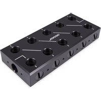
| Product Type | Distribution plate for liquid cooler |
| Dimensions (L x W x D) | 120 x 80 x 30 mm |
| Weight | Approx. 200 g |
| Material | Acrylic and aluminum |
| Fittings | 4x G1/4 |
| Package Contents | 1 distribution plate, 1 double-sided adhesive tape, 2 universal brackets, 4x M3x8 screws, 4x M3x4 screws, 4 screw plugs |
| Main Function | Water distribution between cooling loop components |
| Compatibility | PC liquid cooling loops with G1/4 fittings |
| Operating Temperature | 0 to 50 °C |
| Maximum Pressure | 1 bar |
| Recommended Water Flow | 60-120 L/h |
| Installation | Mounting with adhesive tape, on fan or universal bracket |
| Recommended Coolant | Distilled water, deionized water, or clear Alphacool coolant (CKC or Crystal Ice Water) |
| Maintenance | Regularly check connection tightness |
| Cleaning | Use a soft, dry cloth; do not use harsh cleaners |
| Safety | Read safety instructions carefully before installation |
| Spare Parts Available | Plugs, screws, brackets, adhesive tape |
| Repairability | Seals and fittings can be replaced |
| Warranty | 2 years (depending on retailer) |
Frequently Asked Questions - ES Distro Plate C2 Alphacool
User questions about ES Distro Plate C2 Alphacool
0 question about this device. Answer the ones you know or ask your own.
Ask a new question about this device
Download the instructions for your Liquid CPU cooler in PDF format for free! Find your manual ES Distro Plate C2 - Alphacool and take your electronic device back in hand. On this page are published all the documents necessary for the use of your device. ES Distro Plate C2 by Alphacool.
USER MANUAL ES Distro Plate C2 Alphacool
Mounting with velcro tape 22
Mounting on a fan Location. 23
Mounting on the Universal Bracket. 24
Connecting the Patch Panel 253
startup 34
Francais 35
Read the safety instructions before starting the installation.
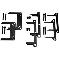
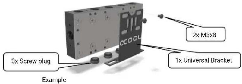
Assembly Material
| Alphacool ES Distro Plate C2 Alphacool ES Distro Plate C3 | 1x Velcro tape | 2x Universal bracket | 4x M3x8 | 4x M3x4 | Screw plug | 4x by Alphacool ES Distro Plate C2 6x by Alphacool ES Distro Plate C3 8x by Alphacool ES Distro Plate C3 |
| Alphacool ES Distro Plate C5 | 2x Fan Bracket | 2x Universal bracket | 4x M3x8 | 4x M3x4 | 4x M3 Nut | 12x Screw plug |
Alphacool International GmbH Alphacool ES Distro Plate C2 / C3 / C5 English
Technical details
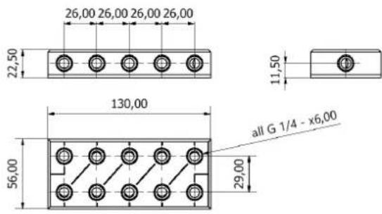
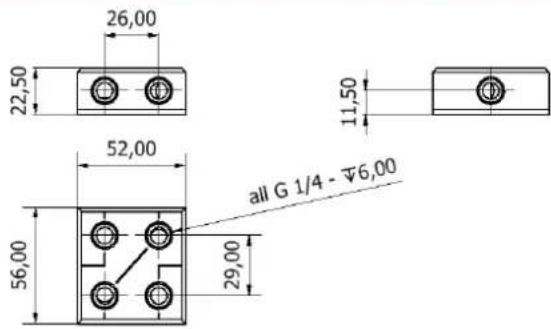
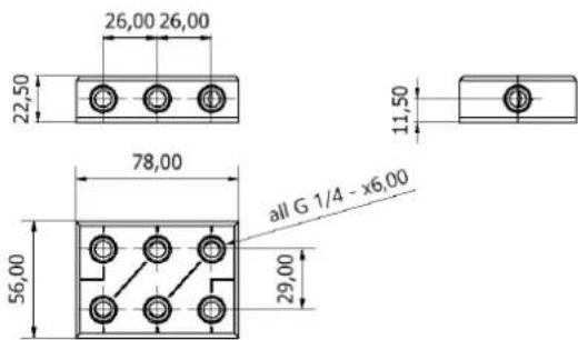
Dimensions in millimetres
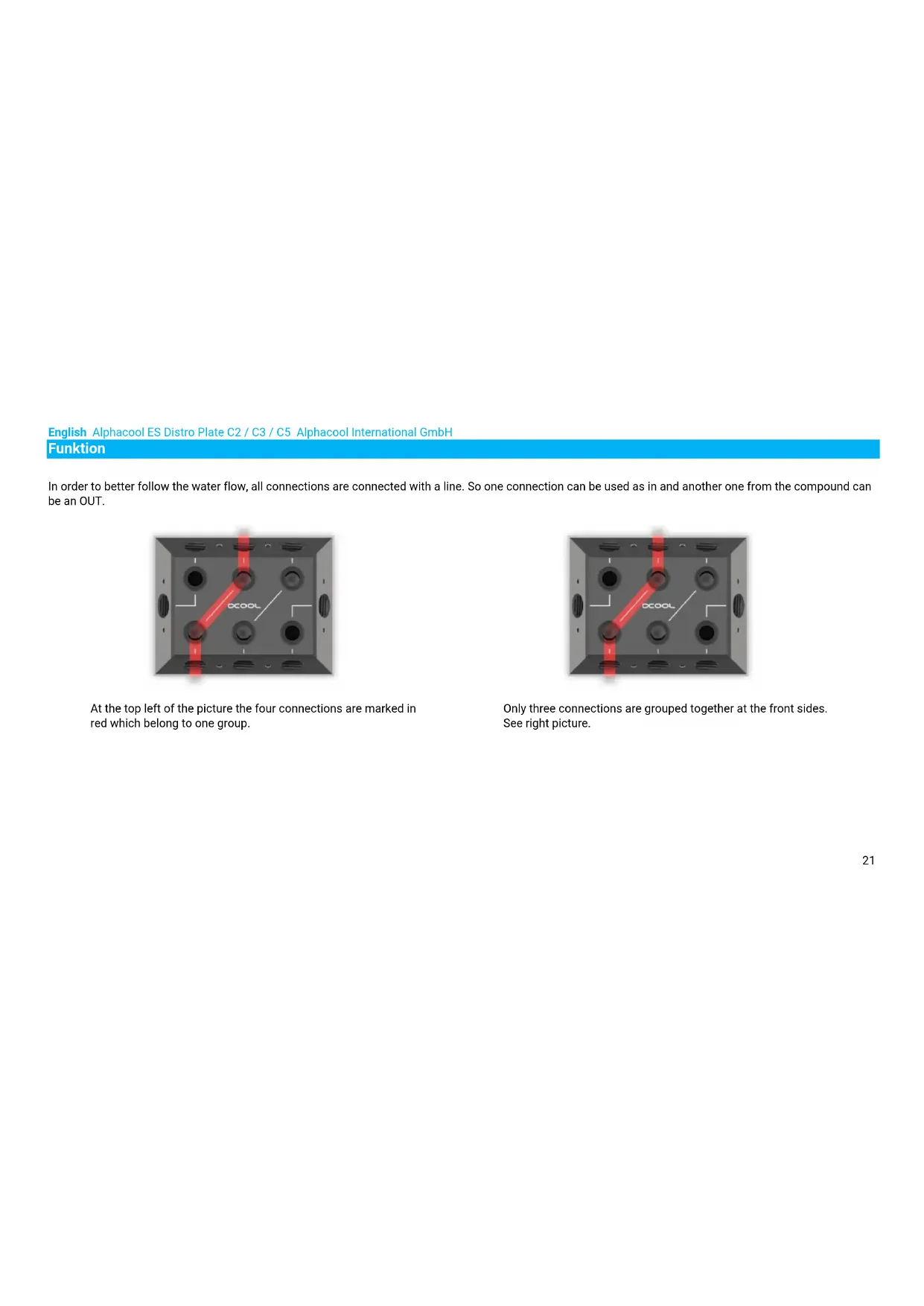
Funktion
In order to better follow the water flow, all connections are connected with a line. So one connection can be used as in and another one from the compound can be an OUT.
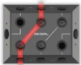
At the top left of the picture the four connections are marked in red which belong to one group.
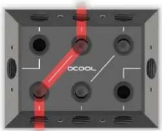
Only three connections are grouped together at the front sides. See right picture.
Alphacool International GmbH Alphacool ES Distro Plate C2 / C3 / C5 English
Assembly
Mounting with velcro tape
1.
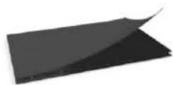
Remove the protective foil of the velcro tape on one side. Do not touch the adhesive surface. The adhesive is difficult to remove.
2.
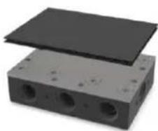
Stick the Velcro tape to the Alphacool ES Distro Plate
3.
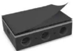
Now remove the second protective foil.
4.
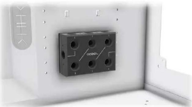
Glue the Alphacool ES Distro Plate to a free space in the case.
English Alphacool ES Distro Plate C2 / C3 / C5 Alphacool International GmbH Mounting on a fan Location
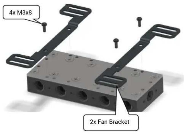
Screw the two suitable holders to the distributor. The holder has slots, so the patch panel can be moved to fit the housing.
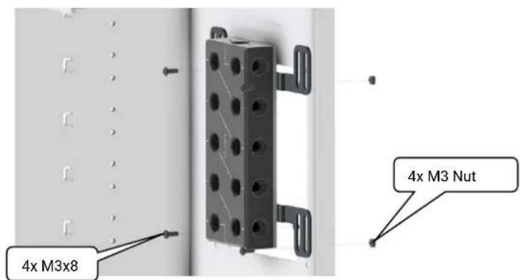
Now mount the patch panel with bracket to a fan location. The patch panel can also be mounted directly on a fan or radiator.
Alphacool International GmbH Alphacool ES Distro Plate C2 / C3 / C5 English
Mounting on the Universal Bracket
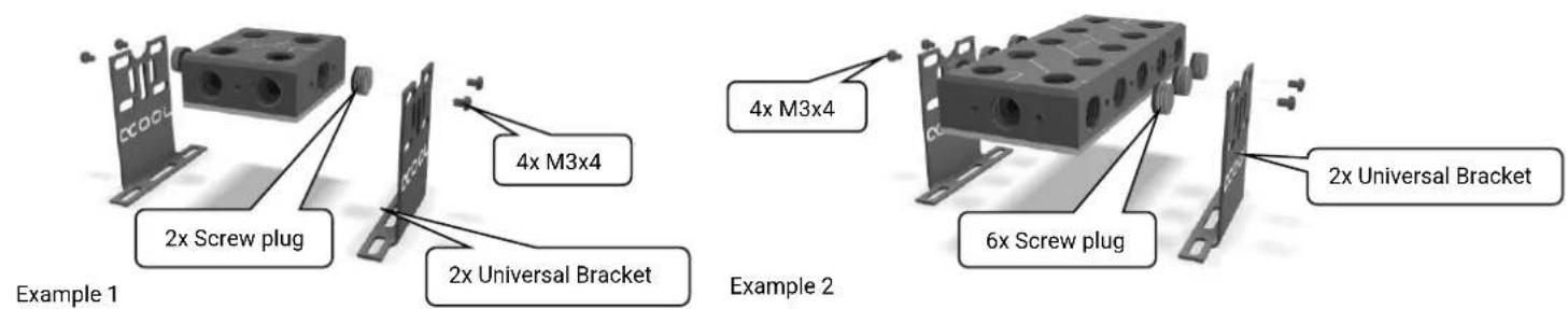

Before doing so, close all connections that are covered. Mount the holders in a free space on the patch panel.
English Alphacool ES Distro Plate C2 / C3 / C5 Alphacool International GmbH
Connecting the Patch Panel
There is a lot of of configurations available. On the following pages we show you some examples.
Example 1 Page 10-11
Example 3 Page 14-15
Example 2 Page 12-13
Example 4 Page 16-17
Alphacool International GmbH Alphacool ES Distro Plate C2 / C3 / C5 English
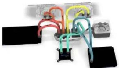
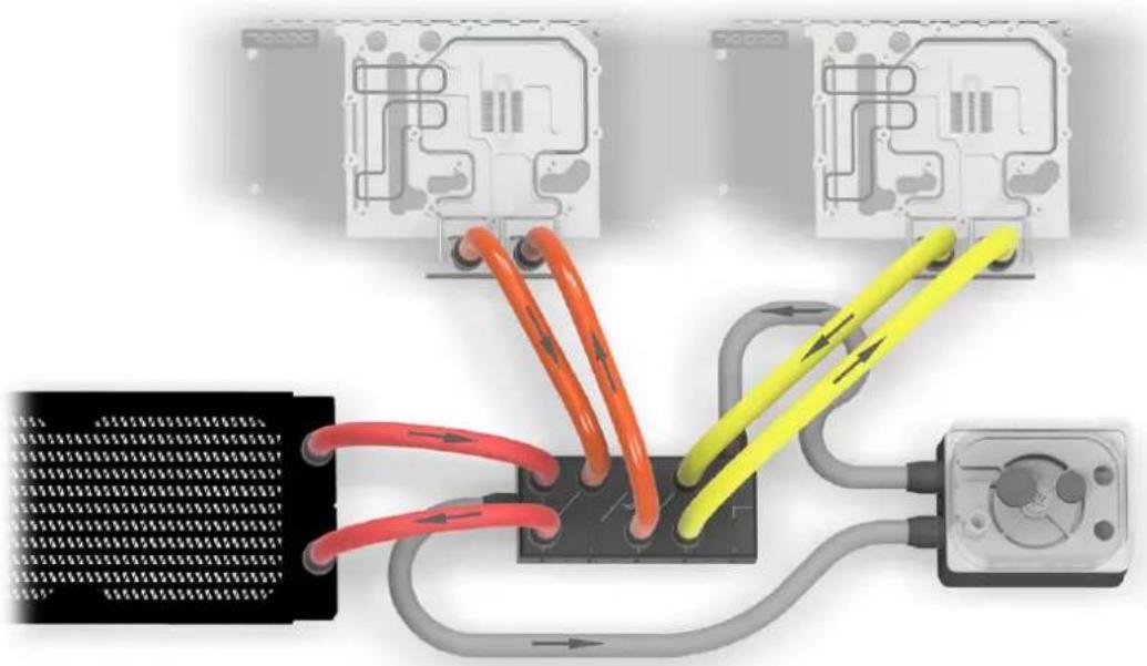
Example 1 - A fully assembled Alphacool ES Distro Plate C3
English Alphacool ES Distro Plate C2 / C3 / C5 Alphacool International GmbH

In this example, IN and OUT is on the front sides of the Alphacool ES Distro Plate C3. The pump with expansion tank is connected here. The individual components such as the cooler and the radiator are connected here via the Alphacool ES Distro Plate.
Note that an OUT must always be connected to an IN to form a water circuit.
Alphacool International GmbH Alphacool ES Distro Plate C2 / C3 / C5 English
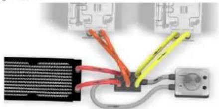
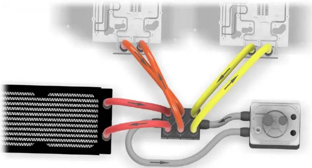
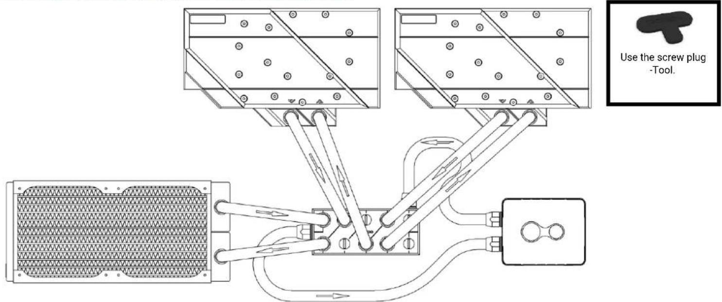
Example 2 - Alphacool ES Distro Plate C3 with side connections

English Alphacool ES Distro Plate C2 / C3 / C5 Alphacool International GmbH

In this example, the graphics cards CPU cooler and the pump with expansion tank are connected to the side of the Alphacool ES Distro Plate C3. Here is good to see how the water flow is directed.
Alphacool International GmbH Alphacool ES Distro Plate C2 / C3 / C5 English
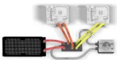
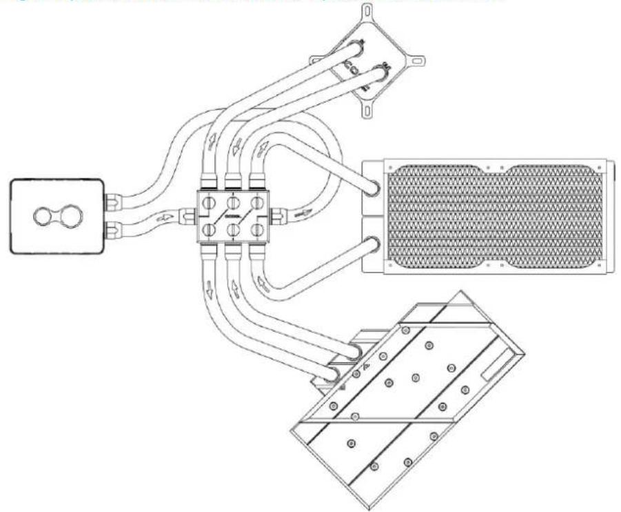
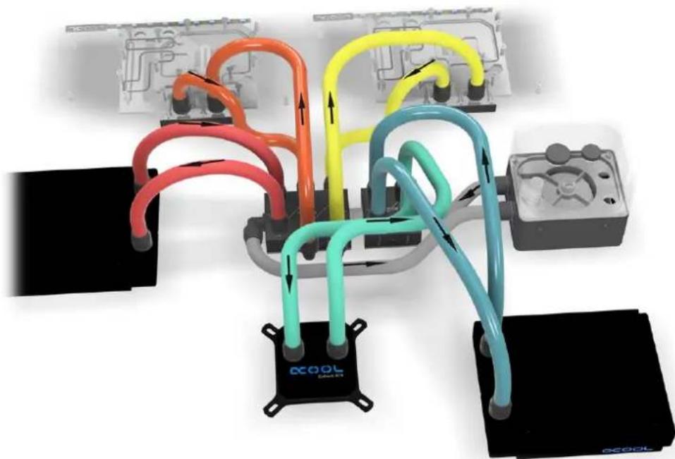
Example 3 - Three components on Alphacool ES Distro Plate C5
English Alphacool ES Distro Plate C2 / C3 / C5 Alphacool International GmbH
In this example, IN and OUT is on the front sides of the Alphacool ES Distro Plate C5. The three components can consist of coolers, pumps or radiators. ATTENTION: In this configuration, two spaces remain unused. Note that an OUT must always be connected to an IN to form a water circuit.
Alphacool International GmbH Alphacool ES Distro Plate C2 / C3 / C5 English
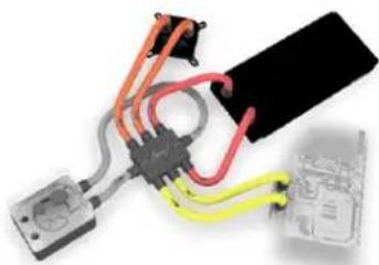
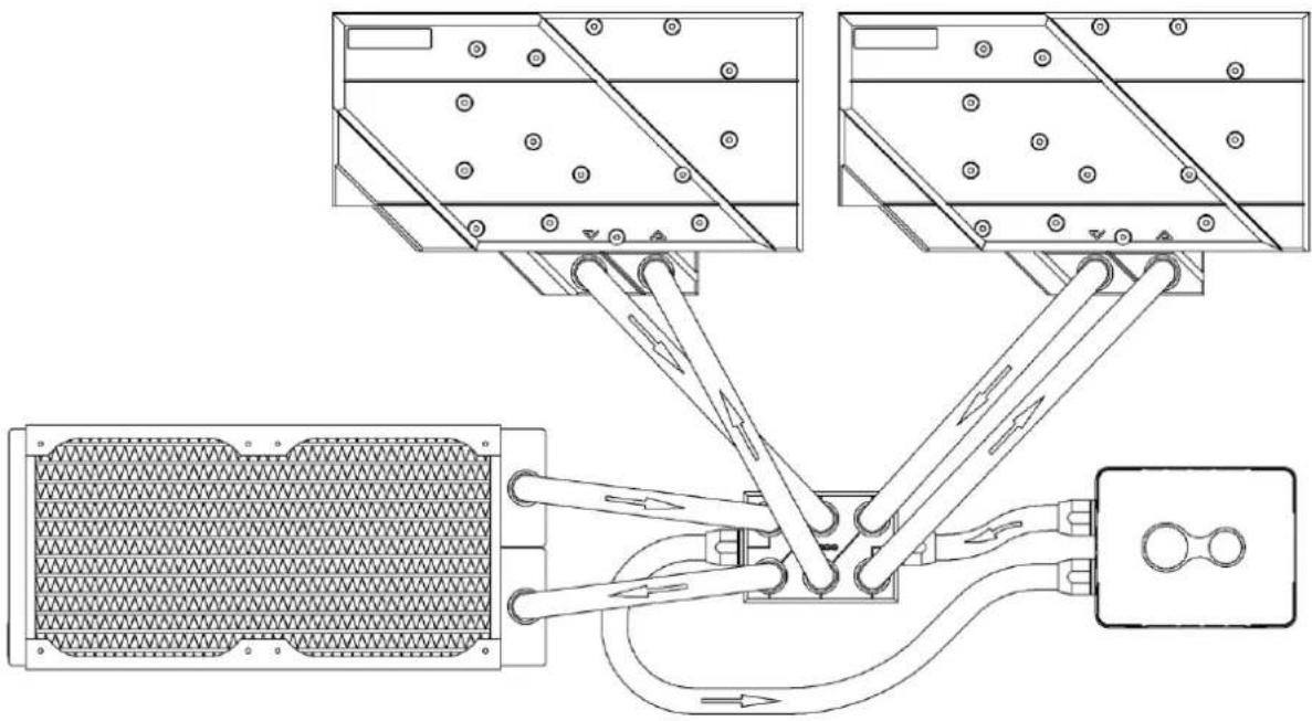
Example 4 - 2 Alphacool ES Distro Plate in series
English Alphacool ES Distro Plate C2 / C3 / C5 Alphacool International GmbH
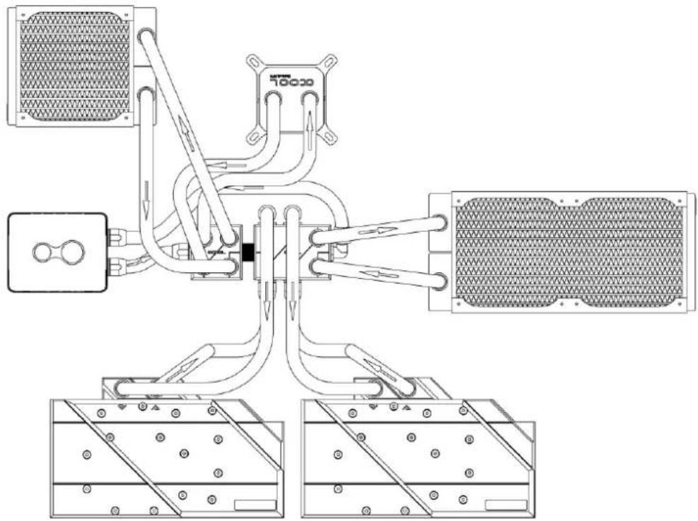

In this example, the graphics cards are connected to the side of the Alphacool ES Distro Plate C3. And two components are connected to an Alphacool ES Distro Plate C2. Both Alphacool ES Distro Plate are connected with an Alphacool HF male to male G1/4 BSPP to G1/4 BSPP.
Alphacool International GmbH Alphacool ES Distro Plate C2 / C3 / C5 English
startup
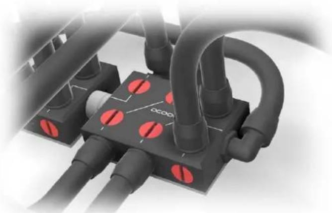
Check all connections. Unused connections must be closed with a screw plug, shown here in red in the picture.
We recommend only clear cooling liquids from our own production (CKC or ice water Crystal no UV liquid!) or pure distilled or osmosis filtered water.
Français Alphacool ES Distro Plate C2 / C3 / C5 Alphacool International GmbH
Français