
STN70SD - Heating STANLEY - Free user manual and instructions
Find the device manual for free STN70SD STANLEY in PDF.
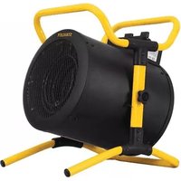
| Product type | Liquid fuel heater (mobile heating) |
| Brand | Stanley |
| Model | STN70SD (ST-70-SS-E) |
| Thermal power | 20.5 kW |
| Fuel consumption | 1.9 L/h |
| Tank capacity | 15.1 L |
| Maximum autonomy | Approximately 8 hours |
| Power supply | 230 V ~ 50 Hz |
| Auxiliary power consumption | 0.087 kW |
| Recommended fuel | CLAMC, diesel 1/2, kerosene, JP8 |
| Starting | Automatic electronic ignition |
| Temperature control | Mechanical thermostat (model T) or simple on/off |
| Cooling cycle | Approximately 7 minutes |
| Required ventilation | Minimum opening of 1950 cm² |
| Usage | Outdoor or well-ventilated indoor, temporary use |
| Safety | Tilt sensor, fuse, thermal protection |
| Fuel filter cleaning | Every 200 operating hours |
| Spark plug cleaning | Every 600 hours, gap 3.5 mm |
| Photocell cleaning | At least once per season |
| Materials | Steel, electrical components |
| Weight (estimated) | Approximately 18 kg |
| Dimensions (L x W x H) | Approximately 70 x 40 x 50 cm |
| Warranty | 2 years (according to local legislation) |
| Manufacturer | Stanley Black & Decker |
Frequently Asked Questions - STN70SD STANLEY
User questions about STN70SD STANLEY
0 question about this device. Answer the ones you know or ask your own.
Ask a new question about this device
Download the instructions for your Heating in PDF format for free! Find your manual STN70SD - STANLEY and take your electronic device back in hand. On this page are published all the documents necessary for the use of your device. STN70SD by STANLEY.
USER MANUAL STN70SD STANLEY
natural_image
Exterior view of a Stanley electric fan with visible grille and base (no text or symbols beyond brand name)CE


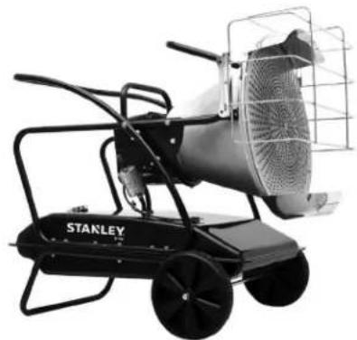
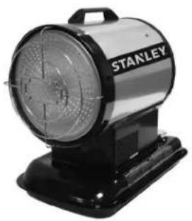
natural_image
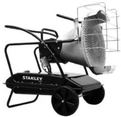
Exterior view of a Stanley electric heater with wheels and a mesh cover (no text or symbols visible)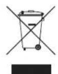

ALGEMENE WAARSCHUWING VOOR GEVAREN:
LEES ALLE INSTRUCTIES IN DEZE HANDLEIDING EN ZORG DAT U ZE
BEGREPEN HEBT VOORDAT U DE KACHEL IN ELKAAR ZET. AANZET OF ONDERHOUDT.
natural_image
Technical line drawing of a cylindrical mechanical component with mounting holes and a bracket, labeled 'Afbeelding 2' (no other text or symbols)
natural_image
Technical line drawing of a mechanical assembly inside a housing, labeled 'Afbeelding 3' (no other text or symbols)LAAT DE KACHEL NOOIT ONBEWAAKT ACHTER MET DE STEKKER IN HET STOPCONTACT
Montage-instructies
ST-125-OFR-E
natural_image
Technical line drawing of a mechanical bracket assembly (no text or symbols)
natural_image
Pure technical line drawing of two curved pipe or duct structures with mounting holes and bolted joints (no text or symbols)LAAT DE KACHEL NOOIT ONBEWAAKT ACHTER MET DE STEKKER IN HET STOPCONTACT
Montage
natural_image
Technical line drawing of a mechanical assembly with a wheel, bolts, and rod (no text or symbols)natural_image
Technical line drawing of a mechanical assembly with rollers and fasteners (no text or symbols)natural_image
Technical line drawing of a mechanical assembly with no visible text or symbolsOnderdelenlijst
Pinnacle Climate Technologies, Inc.
Sauk Rapids, MN 56379 USA
EC REP
Obelis S.A.
© 2021 Stanley Black & Decker, Inc.
STANLEY®
Numéros de modèles
ST-70-SS-E / ST-70T-SS-E / ST-125-OFR-E

natural_image
Exterior view of a Stanley electric fan with visible grille and base (no text or symbols beyond brand name)CE

natural_image
Black-and-white photo of a Stanley electric heater with wheels and a mesh cover (no visible text or symbols)

natural_image
Two identical bolted components shown in isometric view, no text or symbols presentnatural_image
Technical line drawing of a cylindrical mechanical component with mounting flanges and a bracket, labeled Figure 2 (no text or symbols on the diagram itself)
natural_image
Technical line drawing of a mechanical component with internal channels and mounting bracket (no text or symbols)NE JAMAIS LAISSER LE RADIATEUR SANS SURVEILLANCE LORSQU'IL EST BRANCHÉ À UNE SOURCE D'ALIMENTATION.
natural_image
Technical line drawing of a mechanical bracket assembly (no text or symbols)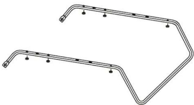
natural_image
Pure technical line drawing of two curved pipe or duct structures with mounting holes and bolted ends (no text or symbols)NE JAMAIS LAISSER LE RADIATEUR SANS SURVEILLANCE LORSQU'IL EST BRANCHÉ À UNE SOURCE D'ALIMENTATION.
Montage
natural_image
Technical line drawing of a mechanical assembly with a wheel, bolt, and rod (no text or symbols)natural_image
Technical line drawing of a mechanical assembly with rollers and fasteners (no text or symbols)natural_image
Technical line drawing of a mechanical assembly with coiled components and mounting brackets (no text or symbols)NE JAMAIS LAISSER LE RADIATEUR SANS SURVEILLANCE LORSQU'IL EST BRANCHÉ À UNE SOURCE D'ALIMENTATION.
Pinnacle Climate Technologies, Inc.
Sauk Rapids, MN 56379 USA
EC REP
Obelis S.A.
Domiciliation :
© 2021 Stanley Black & Decker, Inc.
STANLEY®
Modellnummern
ST-70-SS-E / ST-70T-SS-E / ST-125-OFR-E

natural_image
Exterior view of a Stanley electric fan with visible grille and base (no text or symbols beyond brand name)CE

natural_image
Exterior view of a Stanley electric heater with wheels and control panel (no text or symbols visible)

natural_image
Line drawing of a mechanical lever or bracket (no text or symbols)natural_image
Two identical bolted components shown in isometric view, no text or symbols presentnatural_image
Technical line drawing of a cylindrical mechanical component with mounting brackets and a hinged bracket (no text or symbols)
natural_image
Technical line drawing of a mechanical assembly inside a housing, showing internal components and mounting brackets (no text or symbols)natural_image
Technical line drawing of a mechanical bracket assembly (no text or symbols)
natural_image
Technical line drawing of two curved metal pipe fittings with bolt holes and mounting points (no text or symbols)natural_image
Technical line drawing of a mechanical assembly with a wheel and mounting bracket (no text or symbols)natural_image
Technical line drawing of a mechanical assembly with rollers and fasteners (no text or symbols)natural_image
Technical line drawing of a mechanical assembly with coiled components and mounting brackets (no text or symbols)natural_image
Technical line drawing of a mechanical assembly with two views (top and side), no visible text or symbolsGEBLÄSEMOTORBAUGRUPPE
ST-70-SS-E / ST-70T-SS-E / ST-125-OFR-E
DRUCKEINSTELLUNG:
Teileliste
Pinnacle Climate Technologies, Inc.
Sauk Rapids, MN 56379 USA
EC REP
Obelis S.A.
© 2021 Stanley Black & Decker, Inc.
STANLEY®
Modelos
ST-70-SS-E / ST-70T-SS-E / ST-125-OFR-E

natural_image
Exterior view of a Stanley electric fan with visible grille and base (no text or symbols beyond brand name)CE


natural_image
Exterior view of a Stanley electric heater with wheels and a mesh cover (no text or symbols visible)

natural_image
Technical line drawing of a cylindrical mechanical component with mounting flanges and a bracket, labeled Figura 2 (no text or symbols on the diagram itself)natural_image
Technical line drawing of a mechanical assembly inside a housing, showing internal components and mounting brackets (no text or symbols)NUNCA DEIXAR O AQUECEDOR SEM VIGILÂNCIA QUANDO LIGADO A UMA FONTE DE ENERGIA
natural_image
Technical line drawing of a mechanical bracket assembly (no text or symbols)
natural_image
Pure technical line drawing of two curved pipe or duct structures with mounting holes and bolted joints (no text or symbols)NUNCA DEIXAR O AQUECEDOR SEM VIGILÂNCIA QUANDO LIGADO A UMA FONTE DE ENERGIA
Montagem
natural_image
Technical line drawing of a mechanical assembly with a wheel, bolts, and rod (no text or symbols)natural_image
Technical line drawing of a mechanical assembly with bolts and pulleys (no text or symbols)natural_image
Technical line drawing of a mechanical assembly with curved components and mounting brackets (no text or symbols)ST-125-OFR-E - Bocal
CÉLULA FOTOELÉTRICA:
Lista de peças
NUNCA DEIXAR O AQUECEDOR SEM VIGILÂNCIA QUANDO LIGADO A UMA FONTE DE ENERGIA
Pinnacle Climate Technologies, Inc.
Sauk Rapids, MN 56379 USA
EC REP
Obelis S.A.
Sede social:
© 2021 Stanley Black & Decker, Inc.
STANLEY®
Números de modelos
ST-70-SS-E / ST-70T-SS-E / ST-125-OFR-E

natural_image
Exterior view of a Stanley electric fan with visible grille and base (no text or symbols beyond brand name)CE

natural_image
Black-and-white photo of a Stanley electric heater with wheels and a mesh cover (no visible text or symbols)

natural_image
Technical line drawing of a cylindrical mechanical component with mounting holes and a bracket (no text or symbols)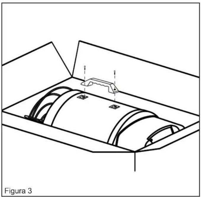
natural_image
Technical line drawing of a mechanical component with internal cavities and mounting bracket (no text or symbols)natural_image
Technical line drawing of a mechanical bracket assembly (no text or symbols)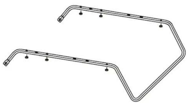
natural_image
Technical line drawing of two curved metal pipe fittings with bolt holes and mounting points (no text or symbols)natural_image
Technical line drawing of a mechanical assembly with a wheel, bolts, and rod (no text or symbols)natural_image
Technical line drawing of a mechanical assembly with bolts and pulleys (no text or symbols)natural_image
Technical line drawing of a mechanical assembly with no visible text or symbolsCOMBUSTIBLE Y DEPÓSITO DE COMBUSTIBLE:
ADVERTENCIA
natural_image
Technical line drawing of a mechanical assembly with no visible text or symbolsCONJUNTO DÉL MOTOR DEL SOPLADOR
ST-70-SS-E / ST-70T-SS-E / ST-125-OFR-E
AJUSTES DE PRESIÓN:
Boquilla ST-125-OFR-E
CÉLULA FOTOELECTRICA
LISTA DE PIEZAS:
Pinnacle Climate Technologies, Inc.
Sauk Rapids, MN 56379 USA
EC REP
Obelis S.A.
© 2021 Stanley Black & Decker, Inc.
STANLEY®
Numery modeli
ST-70-SS-E/ST-70T-SS-E/ST-125-OFR-E

natural_image
Exterior view of a Stanley electric fan with visible grille and base (no text or symbols beyond brand name)CE


natural_image
Black-and-white photo of a Stanley electric heater with wheels and a mesh cover (no visible text or symbols)

natural_image
Isometric line drawing of a mechanical part (no text or symbols on the object itself)karne śruby (2)
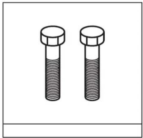
natural_image
Two identical bolted components shown in isometric view, no text or symbols presentUchwyt przenośny
natural_image
Technical line drawing of a cylindrical mechanical component with mounting flanges and a bracket, labeled 'Rysunek 2' (no other text or symbols)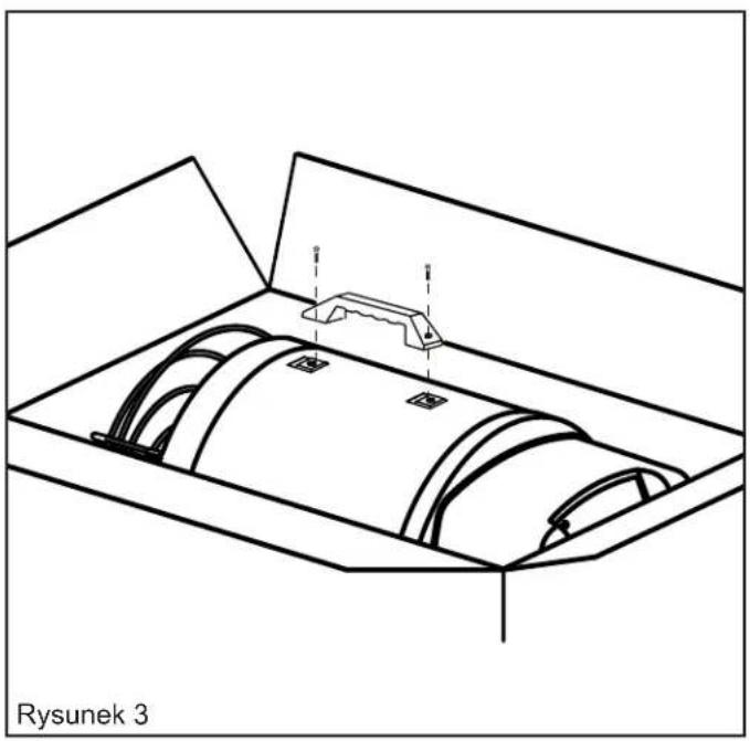
natural_image
Technical line drawing of a mechanical assembly inside a housing, labeled 'Rysunek 3' (no other text or symbols)NIGDY NIE POZOSTAWIAĆ BEZ NADZORU PROMIENNIKA PODŁĄCZONEGO DO ZASILANIA
Instrukcja montażu
ST-125-OFR-E
natural_image
Technical line drawing of a mechanical bracket assembly (no text or symbols)
natural_image
Technical line drawing of two curved metal pipe fittings with bolt holes and mounting points (no text or symbols)NIGDY NIE POZOSTAWIAĆ BEZ NADZORU PROMIENNIKA PODŁĄCZONEGO DO ZASILANIA
Montaż
natural_image
Technical line drawing of a mechanical assembly with a wheel, bolts, and rod (no text or symbols)natural_image
Technical line drawing of a mechanical assembly with rollers and fasteners (no text or symbols)natural_image
Technical line drawing of a mechanical assembly with no visible text or symbolsNIE NALEŻY STOSOWAĆ SPUSTÓW BENZYNY ANI
SKRZYNI KORBOWEJ.
Lista części
Pinnacle Climate Technologies, Inc.
Sauk Rapids, MN 56379 USA
EC REP
Obelis S.A.
Siedziba firmy:
© 2021 Stanley Black & Decker, Inc.
STANLEY®
Model Numbers
ST-70-SS-E / ST-70T-SS-E / ST-125-OFR-E
natural_image
Exterior view of a Stanley electric fan with visible grille and base (no text or symbols beyond brand name)CE


natural_image
Exterior view of a Stanley electric heater with wheels and control panel (no text or symbols visible)

This product is not suitable for primary heating purposes.
CONSUMER: READ AND SAVE THESE INSTRUCTIONS
DANGER
GENERAL HAZARD WARNING:
READ AND UNDERSTAND ALL OF THE INSTRUCTIONS IN THIS MANUAL
BEFORE ASSEMBLING, STARTING, OR SERVICING THE HEATER. Be sure to comply with the instructions and warnings provided with this heater. Failure to comply can result in fire or explosion that can cause property loss, bodily injury, or loss of life. Only persons who can follow and understand these instructions should operate or service this heater. If you need heater info; such as an operating manual, labels, etcetera, contact the manufacturer.
▲ DANGER
NOT FOR USE IN RESIDENTIAL LIVING AREAS OR IN ENCLOSED SPACES WITHOUT ADEQUATE VENTILATION. FOR OUTDOOR USE. INDOOR USE
PERMITTED ONLY FOR: THE TEMPORARY HEATING OF ADEQUATELY VENTILATED BUILDINGS OR STRUCTURES UNDER CONSTRUCTION, ALTERATION OR REPAIR. This is an unvented portable heater that uses air (Oxygen) from within the area in which it is used. Failure to provide adequate combustion and ventilation air will result in asphyxiation, carbon monoxide poisoning, bodily injury or death. Refer to “Ventilation” on Page 8.
NEVER LEAVE HEATER UNATTENDED WHILE BURNING OR WHILE CONNECTED TO A POWER SOURCE
Table Of Contents
Safety Information 1-2
Features and Specifications 3-4
Assembly 5-7
Ventilation....8
Operation....8-9
Maintenance....10-11
Troubleshooting Guide 12
Wiring Diagrams....13
Exploded Views 14-16
Parts List.... 14,15,17
Safety Information
▲ WARNING
FIRE, BURN, INHALATION AND EXPLOSION HAZARD. Keep combustibles such as; building materials, paper or cardboard a safe distance away from the heater used by these instructions. Never use the heater in spaces which contain products one, solvents, paint thinners, dust particles, volatile or airborne combustibles or any chemicals. This is an unvented portable heater. It uses air (Oxygen) from the area in d. Adequate combustion and ventilation air must be provided. Refer to “Ventilation” risk fuel storage should be a minimum of 25 feet / 7.6 meters from heater.
▲WARNING
DO NOT OPERATE THIS HEATER UNTIL YOU HAVE READ AND THOROUGHLY UNDERSTAND THESE SAFETY AND OPERATING INSTRUCTIONS.
Failure to comply with the precautions and instructions provided with this heater can result in death, serious bodily injury, property loss or damage from the hazards of fire, soot production, explosions, burns, asphyxiation or carbon monoxide poisoning. Only persons who can read and understand these instructions should use or service this heater.
▲WARNING
DO NOT START THE HEATER WHEN EXCESS OIL HAS ACCUMULATED.
▲ WARNING
DO NOT START THE HEATER WHEN THE CHAMBER IS HOT.
THE INSTALLATION OF THIS HEATER SHALL COMPLY WITH THE REGULATIONS OF THE AUTHORITIES HAVING JURISDICTION.
This appliance can be used by children aged from 8 years and above and persons with reduced physical, sensory or mental capabilities or lack of experience or and knowledge if they have been given supervision or instruction concerning use of the appliance in a safe way and understand the hazards involved. Children shall not play with the appliance. Cleaning and user maintenance shall not be made by children without supervision.

Look for this icon throughout the manual for helpful tips on how to assemble, use and clean your OFR/SS Heater.

Read The Instruction manual: When this symbol is marked on a product, it means that the instruction manual must be read.
WARNING! Never touch heater until heater has cooled off.
NEVER LEAVE HEATER UNATTENDED WHILE BURNING OR WHILE CONNECTED TO A POWER SOURCE
Safety Information
▲WARNING
RISK OF INDOOR AIR POLLUTION!
The products described in this manual are Paraffin/Diesel direct-fired, forced air heaters. Paraffin/Diesel forced air heaters are primarily intended for use for temporary heating of buildings under construction, alteration or repair. Direct-fired means that all of the combustion products of the heater enter the heated space. This appliance is rated at 98% combustion efficiency, but does produce small amounts of carbon monoxide.
▲WARNING
CARBON MONOXIDE POISONING MAY LEAD TO DEATH!
Carbon monoxide is toxic. Humans can tolerate only small amounts of carbon monoxide and so precautions should be taken to provide proper ventilation. Failure to provide proper ventilation in accordance with the instructions in this manual can result in death.
People with breathing problems should consult a physician before using this heater.
Early signs of carbon monoxide poisoning resemble the flu. Symptoms of improper ventilation / carbon monoxide poisoning are:
Headache • Dizziness • Nausea • Dry Mouth Sore Throat • Burning of Nose and Eyes
If you experience any of these symptoms: GET FRESH AIR AT ONCE! Have your heater serviced and check for proper ventilation. Some people are more affected by carbon monoxide than others. These include: pregnant women, those with heart or lung problems, anemia or those under the influence of alcohol or at high altitudes.
FOR OUTDOOR USE. INDOOR USE PERMITTED ONLY FOR: The temporary heating of adequately ventilated buildings or structures under construction, alteration or repair! Provide at least 2,800 sq. cm (3 sq. ft.) opening of outside air for every 29 kW(100,000 Btu/Hr) heater rating. Refer to “Ventilation” on page 8 for further instructions.
▲WARNING
RISK OF ELECTRIC SHOCK!
ALWAYS use only the electrical power (voltage and frequency) specified on the model plate of the heater.
ALWAYS use only three-prong, grounded outlet and extension cord.
ALWAYS use only 14 AWG or better extension cord.
ALWAYS unplug the heater when not in use.
ALWAYS install the heater so that it is not directly exposed to water spray, rain, dripping water, or wind.
NEVER use fuels such as gasoline, benzine, paint
▲ WARNING
RISK OF BURNS, FIRE AND EXPLOSION!
thinners or other oil compounds in this heater.
NEVER refill the heater's fuel tank while the heater is operating or still hot. This heater is EXTREMELY HOT while in operation.
NEVER block air outlet (front).
NEVER use duct work in front of heater.
NEVER move or handle heater while still hot.
NEVER transport heater with fuel in tank.
NEVER use with an external fuel tank.
Keep all combustible materials away from this heater.
WARNING
KEEP CHILDREN, ANIMALS, CLOTHING AND COMBUSTIBLES AWAY FROM HEATER.
| Minimum Clearance From Combustibles | ||
| ST-70-SS-E / ST-70T-SS-E ST-125-OFR-E | ||
| Top | 1.2 m 1.2 m | |
| Sides | 1.2 m 1.2 m | |
| Front | 2.4 m 2.4 m | |
ALWAYS locate heater on a stable and level surface.
If your heater is equipped with a thermostat, once it is plugged in, it can start at anytime in accordance with the thermostat setting.
NEVER LEAVE HEATER UNATTENDED WHILE BURNING OR WHILE CONNECTED TO A POWER SOURCE
Specifications
| Model # ST-70-S | S-E / ST-70T-SS-E ST-125-OFR-E | |
| Rating: kW 20,5 36,6 | ||
| Fuel Consumption: L/Hr 1,9 3.2 | ||
| Fuel Tank Capacity: L 15,1 53 | ||
| Max Operating Hours 8 20 | ||
| Volts: AC/Hz 230VAC / 50Hz 230VAC / 50Hz | ||
| Heating Area m^2 | 162 | 290 |
Specifications subject to change without notice.
Features
ST-70-SS-E / ST-70T-SS-E
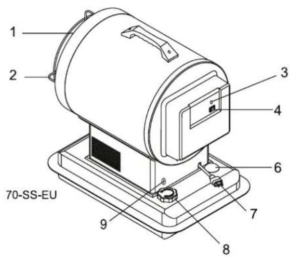
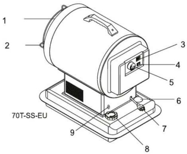

- HEAT PLATE
- SAFETY GUARD
- LAMP
- OPERATING SWITCH
- THERMOSTAT KNOB
- FUEL GAUGE
- POWER CORD
- FUEL CAP
- AIR ADJUSTMENT SCREW
Figure 1
NEVER LEAVE HEATER UNATTENDED WHILE BURNING OR WHILE CONNECTED TO A POWER SOURCE
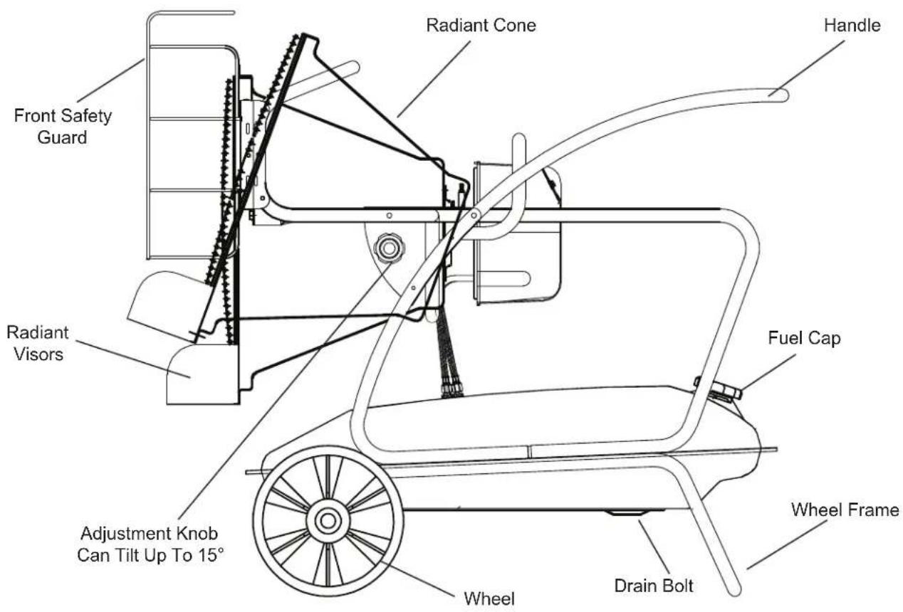
Features
ST-125-OFR-E
NEVER LEAVE HEATER UNATTENDED WHILE BURNING OR WHILE CONNECTED TO A POWER SOURCE
Assembly Instructions
ST-70-SS-E / ST-70T-SS-E
- Remove the heater and all packaging materials from the shipping carton.
Note: Save the box and packaging materials for future storage.
What's In The Box
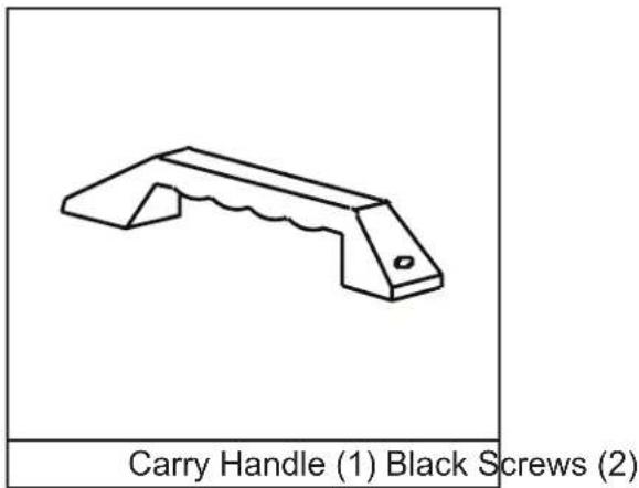
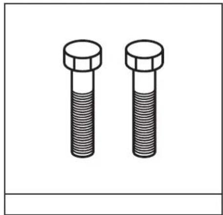
natural_image
Two identical bolted components shown in isometric view, no text or symbols presentCarry Handle Assembly
- Align holes in the upper housing with the 2 holes in the handle as shown in Figure 2.
- Insert screws and tighten firmly.
Tools Needed:
- Phillips Head Screw Driver
i Attach the handle while still in the box for easier unpacking. (See Figure 3)
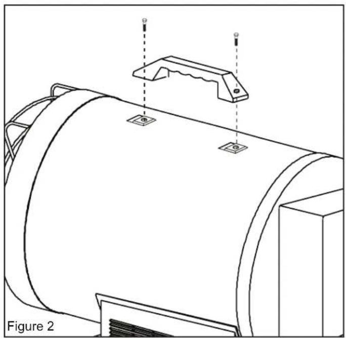
natural_image
Technical line drawing of a cylindrical mechanical component with mounting flanges and a bracket, labeled Figure 2 (no text or symbols on the diagram itself)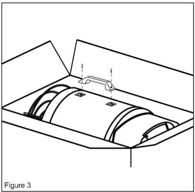
natural_image
Technical line drawing of a mechanical component with internal cavities and mounting bracket (no text or symbols)NEVER LEAVE HEATER UNATTENDED WHILE BURNING OR WHILE CONNECTED TO A POWER SOURCE
Assembly Instructions
ST-125-OFR-E
- Remove the heater and all packaging materials from the shipping carton.
Note: Save the box and packaging materials for future storage.
What's In The Box
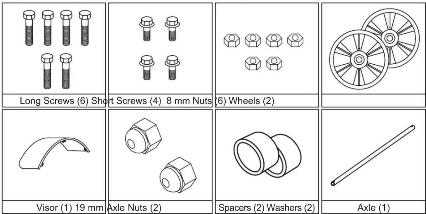
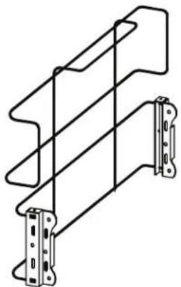
Safety Guards (Top, Front) Wheel Frame
natural_image
Technical line drawing of a mechanical bracket assembly (no text or symbols)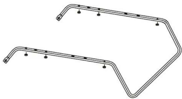
natural_image
Technical line drawing of two curved metal pipe fittings with bolt holes and mounting points (no text or symbols)NEVER LEAVE HEATER UNATTENDED WHILE BURNING OR WHILE CONNECTED TO A POWER SOURCE
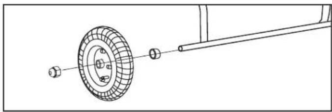
Assembly
- Slide axle through Wheel Frame and attach wheels, washers and nuts.
natural_image
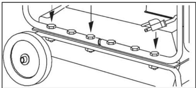
Technical line drawing of a mechanical assembly with a wheel, bolts, and rod (no text or symbols)- Place main structure on wheel frame and fasten with long screws provided.
natural_image
Technical line drawing of a mechanical assembly with rollers and fasteners (no text or symbols)- Attach safety guard to front of heater with screws provided.
natural_image
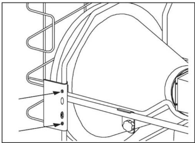
Technical line drawing of a mechanical assembly with no visible text or symbols- Attach Radiant Visors to the top and bottom rear of the Radiant Cone Assembly using extra screws included.
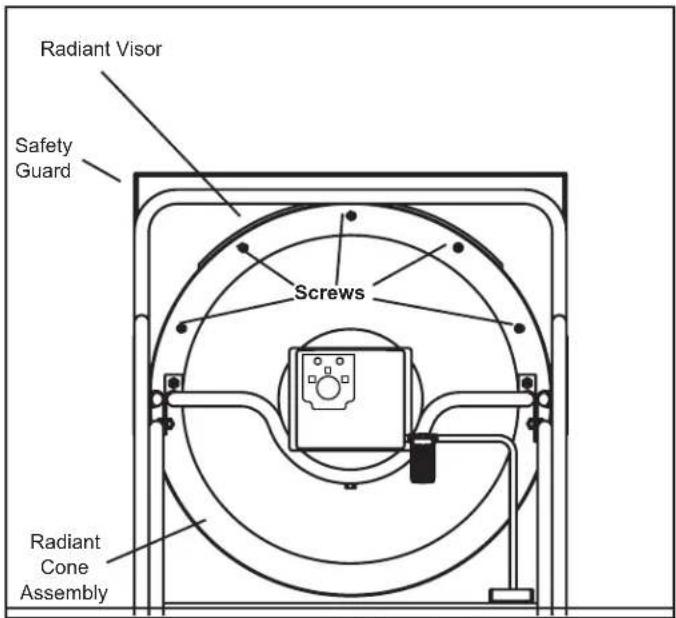
- Attach top safety guard using the two outer-most extra screws on the top of the radiant cone (See photo).
Note: Save the box and packaging materials for future storage.
NEVER LEAVE HEATER UNATTENDED WHILE BURNING OR WHILE CONNECTED TO A POWER SOURCE
Operation
Fueling The Heater:
Paraffin
For optimal performance of this heater, it is strongly suggested that Paraffin be used. Paraffin has been refined to virtually eliminate contaminants, such as sulfur, which can cause a rotten egg odor during the operation of the heater. Using diesel fuel can cause excess soot production. Do not use Bio-Diesel or Farm “red” diesel as this fuel will damage your heater’s seals and filter.
Factory tested for use with paraffin, no. 1 & no.2 diesel, JP8/Jet A Fuel, no. 1 and no. 2 fuel oil.
DANGER
NEVER REFUEL THIS HEATER WHILE IT IS HOT OR
OPERATING. FIRE OR EXPLOSION COULD RESULT.
CAUTION
NEVER FILL THE FUEL TANK INDOORS. ALWAYS FILL
THE TANK OUTDOORS. BE SURE THAT THE HEATER IS ON LEVEL GROUND WHEN FUELING, AND NEVER OVERFILL THE TANK.
▲WARNING
DO NOT USE GASOLINE OR CRANKCASE DRAININGS.
- NEVER use fuel such as, benzene, alcohol, white gas, camp stove fuel, paint thinners, or other oil compounds in this heater. THESE ARE VOLATILE FUELS THAT CAN CAUSE A FIRE OR EXPLOSION.
- NEVER store Paraffin in the living space. Paraffin should be stored in a well ventilated area outside the living area.
- NEVER store Paraffin in direct sunlight or near a source of heat.
- NEVER use Paraffin that has been stored from one season to the next. Paraffin deteriorates over time. OLD Paraffin WILL NOT BURN PROPERLY IN THIS HEATER.
NOTE: Paraffin should only be stored in a blue container that is clearly marked "Paraffin." Never store Paraffin in a red container. Red is associated with gasoline.
Ventilation:
- Risk of indoor air pollution and Carbon Monoxide Poisoning. Use heater only in well ventilated areas.
- Refer to Safety Information on pages 1-2 for information about Carbon Monoxide Poisoning.
- ALWAYS provide a fresh air opening in the heated space of at least 2,800 square centimeters (3 sq. ft) for each 29 kW (100,000 Btu / Hr.) of heater output. Provide a larger opening if more heaters are being used.
DANGER
CARBON MONOXIDE POISONING MAY LEAD TO DEATH!
▲WARNING
This appliance is designed to operate safely at a minimum erature of -20^ C.
WARNING
Use caution when servicing in wet areas. Disconnect power other mains and keep all electrical from becoming wet. Only a politician should service the
WARNING
A qualified technician is required to install, adjust and ary; convert this heater for use I types.
| Minimum Ventilation Opening Needed | |
| ST-70-SS-E / ST-70T-SS-E | ST-125-OFR-E |
| 1950 cm ^2 | 3484 cm ^2 |
NEVER LEAVE HEATER UNATTENDED WHILE BURNING OR WHILE CONNECTED TO A POWER SOURCE
Operation: ST-70-SS-E / ST-70T-SS-E / ST-125-OFR-E
Starting the Heater: (Ignition)
- Fill the tank with Paraffin or other approved fuel until needle on fuel gauge points to "F".
- Replace fuel cap and tighten firmly.
- Connect the heater to a three prong (grounded) power source. You must use a three prong (grounded) extension cord that is at least 1.8 meters long and is a minimum of 14 AWG rating.
NOTE: On first ignition or after refueling, you may hear a grinding sound just before ignition. This is the fuel pump removing the air from the fuel line. Your heater will start up within seconds. If it does not start repeat start-up procedures with fuel gauge reading at least 1/2 tank.
NOTE: Smoking may occur on first ignition.
NOTE: The electrical components of these heaters are protected by a fuse mounted in the PC board. If the heater fails to ignite, check this fuse first and replace if necessary. Also check the power source to be sure the proper voltage is being provided to the heater.
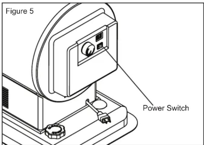
- Complete steps 1-3 above.
- Push the power switch to the "ON" position. The power indicator lamp will light and heater will ignite. (See Figure 5)
Stopping the Heater: (Cool Down)
-
Turn the power switch to the "OFF" position. Combustion will stop and the Cooling Cycle will begin.
-
ST-70-SS-E / ST-70T-SS-E: approx. 7 mins
- ST-125-OFR-E: approx 3 mins
When the Cooling Cycle is complete the fan will stop running and it will be safe to unplug the heater.
NOTE: Unplugging the heater before the Cooling Cycle has been completed may cause overheating, possible damage to the heater and heat plate.
Restarting the Heater:
- Wait ten seconds after Cooling Cycle has been completed.
- Follow all start-up procedures above.
WARNING
DO NOT disconnect heater from power source before has been completed.
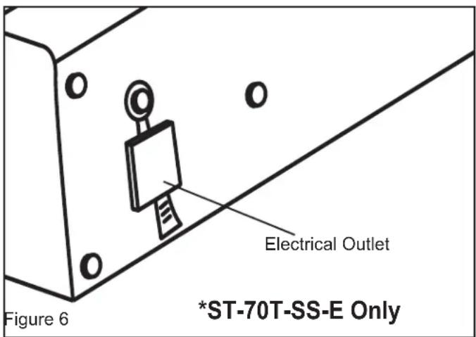
Electrical Outlet (ST-70T-SS-E Only):
- Never plug an appliance with more than a 5 amp rating into this outlet (See Figure 6).
- Always keep outlet covered when not in use
NEVER LEAVE HEATER UNATTENDED WHILE BURNING OR WHILE CONNECTED TO A POWER SOURCE
Maintenance: ST-70-SS-E / ST-70T-SS-E / ST-125-OFR-E
Long Term Storage:
- Unscrew the fuel cap.
- Using an approved siphon, remove the Paraffin or diesel.
- Using a small amount of Paraffin or diesel, rinse and swirl the fuel inside the fuel tank
NOTE: NEVER MIX WATER WITH FUEL. It will cause rust inside the tank.
- Empty the tank completely.
IMPORTANT: Never store leftover Paraffin between seasons, using old fuel can damage heater.
Store Heater in a dry, well ventilated area.
- Be sure that the storage area is free of dust and corrosive vapors. Repack the heater in the original packaging and keep user's manual in an easily accessible place.
Service:
DO NOT TAMPER WITH THE UNIT. HAVE AN EXPERIENCED SERVICEMAN MAKE ANY NECESSARY ADJUSTMENT OR REPAIRS.
WARNING
Never service heater while it is plugged in or hot!
We suggest following a maintenance schedule as follows:
FUEL / FUEL TANK:
Flush tank every 200 hours of operation or as needed. DO NOT flush with water, use fresh Paraffin only.

TIP: Follow the long term storage instructions to flush the tank.
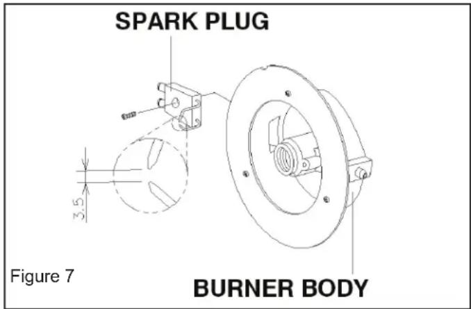
SPARK PLUG:
Clean and re-gap every 600 hours of operation or replace as needed. After removing the Spark Plug, clean the terminals with a wire brush. Re-gap the terminals to 0.140" (3.5mm). (See Figure 7)
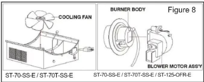
FAN BLADES:
The fan blades should be cleaned at least once per heating season, depending on conditions. Remove all accumulated dust and dirt with a burst of condensed air. (See Figure 8)
PRESSURE ADJUSTMENTS:
Proper pressure is dependent on the fuel type the unit will be running. When smoking or non-ignition occurs, remove the lower panel. Locate the brass screw on the fuel pump to the left of the fuel line.
If you are experiencing smoking or fuel dripping from the unit, turn the screw clockwise 1/8 to 1/4 of a turn to increase the fuel pressure until the unit is operating properly.
If you are experiencing extended flames from the front of the unit, turn the screw 1/8 to 1/4 of a turn counterclockwise to reduce the air pressure until the unit is operating properly.
NEVER LEAVE HEATER UNATTENDED WHILE BURNING OR WHILE CONNECTED TO A POWER SOURCE
Maintenance: ST-70-SS-E / ST-70T-SS-E / ST-125-OFR-E
Service (Continued):
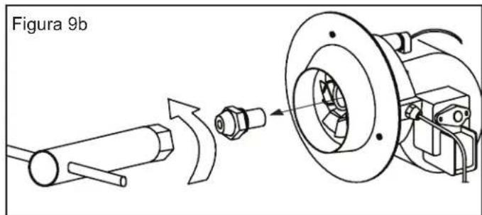
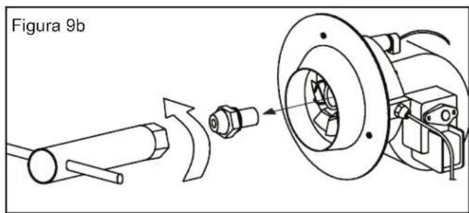
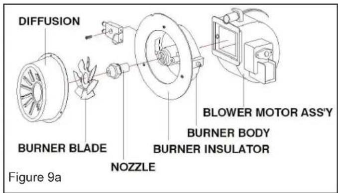
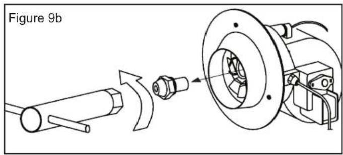
NOZZLES:
Nozzles should be cleaned or replaced at least once per heating season. Contaminated fuel could make this necessary immediately. To clean dirt from nozzle, blow compressed air through nozzle front. It may be necessary to soak nozzle in clean Paraffin or diesel to help loosen any particles. (See Figure 9)
ST-70-SS-E / ST-70T-SS-E Nozzle
ST-125-OFR-E Nozzle
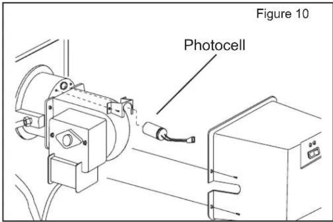
PHOTOCELL:
The photocell should be cleaned at least once per heating season or more depending on conditions. Use a cotton swab and water or alcohol to clean the lens of the photocell. Be certain to reinstall the photocell in proper position as shown below. (See Figure 10)
FILTERS:
The fuel filter and oil filter should be cleaned at least twice per heating season by rinsing it in clean Paraffin or diesel. Contaminated or old fuel could make cleaning necessary immediately. (See Figure 11)
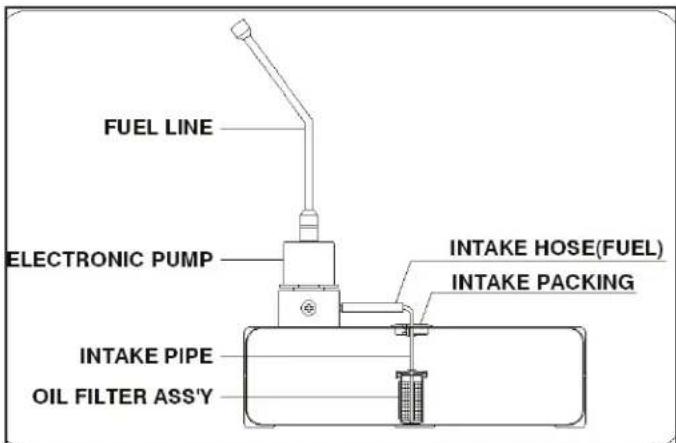
Figure 11
NEVER LEAVE HEATER UNATTENDED WHILE BURNING OR
WHILE CONNECTED TO A POWER SOURCE
Troubleshooting Guide: ST-70-SS-E / ST-70T-SS-E / ST-125-OFR-E
| Problem Possible | Cause Solution | |
| Heater fires, but shuts down after a short period of time. | 1. Dirty Fuel Filter.2. Nozzle Dirty.3. Photocell Dirty.4. Photocell not installed properly.5. Photocell Defective.6. Improper electrical connection between Circuit Board and Photocell.7. Cooling Fan is obstructed8. Improper pressure. | 1. Clean/replace Fuel Filter.2. Clean/replace Nozzle3. Clean/replace Photocell.4. Adjust Photocell position.5. Replace Photocell.6. Check wiring connections (See Wiring Diagrams, Page 11).7. Check to be sure cooling fan is not obstructed.8. Adjust pump pressure. |
| Heater will not operate, or motor runs for short time. | 1. No Paraffin/diesel in fuel tank.2. Corroded Spark Plug or incorrect plug gap.3. Dirty Fuel Filter.4. Dirty Nozzle.5. Moisture in Fuel/Fuel Tank.6. Improper electrical connection between Transformer and Circuit Board.7. Transformer Wires not connected to Spark Plug.8. Defective Transformer. | 1. Fill tank with fresh Paraffin/diesel.2. Clean/replace Spark Plug.3. Clean/replace Fuel Filter.4. Clean/replace Nozzle.5. Rinse out fuel tank with clean fresh Paraffin/diesel.6. Inspect all electrical connections. (See Wiring Diagrams, Page 11).7. Re-attach Transformer wires to Spark Plug.8. Replace Transformer. |
| Fan does not operate when heater is plugged in and Operating Switch is in the “ON” position. | 1. Broken electrical connection between Circuit Board and motor.2. Not enough amps available to power heater. | 1. Inspect all electrical connections on Wiring Diagrams (Page 11).2. Use a new extension cord or try another electrical socket. |
| Heater makes grinding noise. | 1. Air in fuel pump. 1. Sound will stop after 3 seconds. If grinding sound continues, add fuel to tank. | |
| Heater does not turn on and the lamp is not lit. | 1. Temperature limit sensor has over-heated.2. No electrical power.3. Fuse break down.4. Improper electrical connection between Temperature Limit Sensor and Circuit Board. | 1. Push Operating Switch to “OFF” and allow heater to cool for 5 minutes.Push Operating Switch back to “ON”.2. Check power cord and extension cord to insure of proper connection.Test power supply.3. Check/replace Fuse.4. Inspect all electrical connections. (See Wiring Diagrams, Page 11). |
| Poor combustion and / or soot production. | 1. Pump Pressure.2. Poor fuel quality. | 1. Be sure pump pressure is adjusted correctly.2. Be sure Paraffin/diesel is not old or contaminated. |
NEVER LEAVE HEATER UNATTENDED WHILE BURNING OR WHILE CONNECTED TO A POWER SOURCE
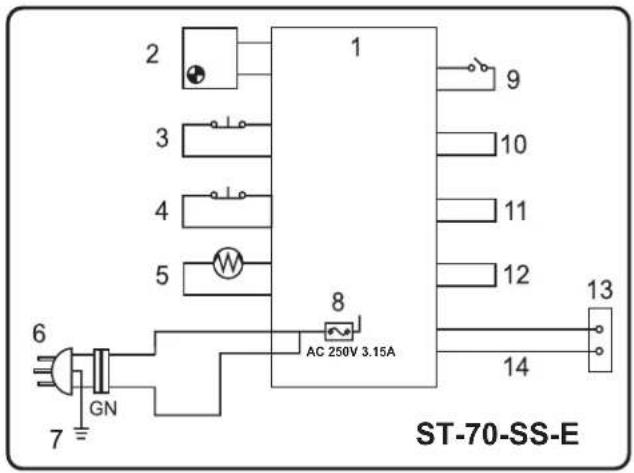
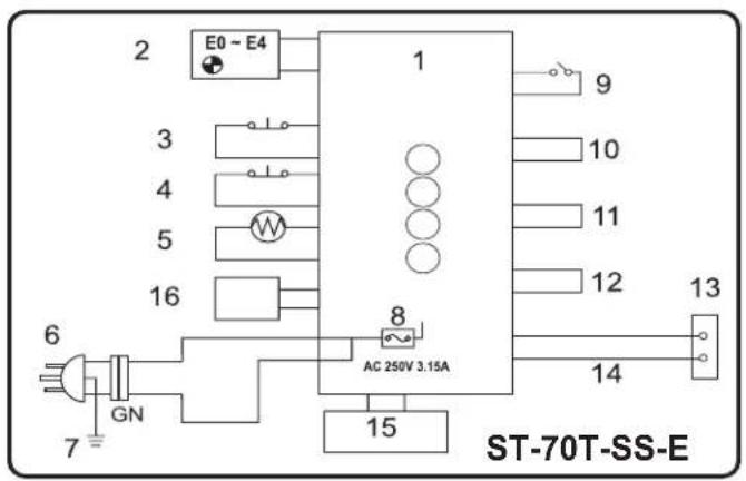
Wiring Diagrams

- PANEL PCB
- OPERATION LAMP
- TIP SWITCH
- HIGH LIMIT SWITCH
- PHOTOCELL
-
POWER PLUG
-
EARTH
- FUSE
- OPERATING SWITCH
- BLOWER MOTOR
- COOLING MOTOR
-
PUMP
-
SPARK PLUG
- IGNITOR
- TEMPERATURE SENSOR
- THERMISTOR
GN. GREEN
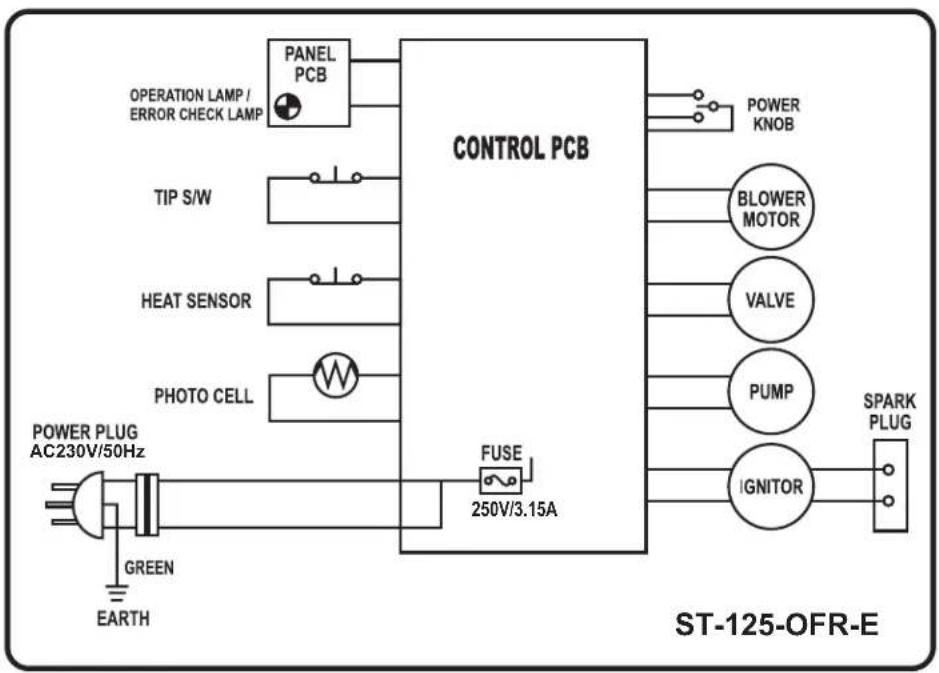
flowchart
graph LR
    A["POWER PLUG AC230V/50Hz"] --> B["GREEN EARTH"]
    B --> C["PANEL PCB"]
    C --> D["CONTROL PCB"]
    D --> E["POWER KNOB"]
    D --> F["BLOWER MOTOR"]
    D --> G["VALVE"]
    D --> H["PUMP"]
    D --> I["IGNITOR"]
    I --> J["SPARK PLUG"]
    D --> K["FUSE 250V/3.15A"]
    style A fill:#f9f,stroke:#333
    style J fill:#ccf,stroke:#333
NEVER LEAVE HEATER UNATTENDED WHILE BURNING OR WHILE CONNECTED TO A POWER SOURCE
Exploded View
ST-70-SS-E
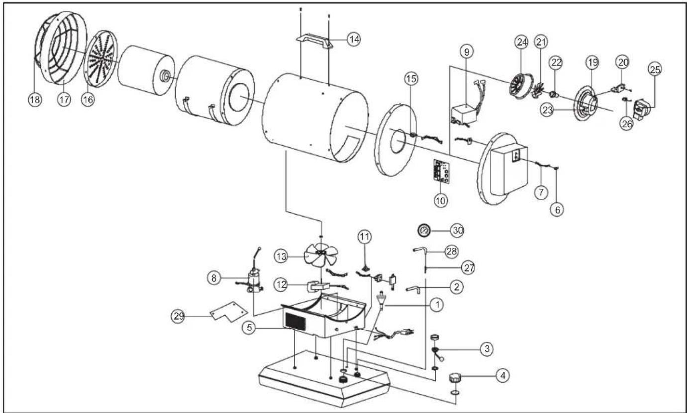
Parts List
| 1 Fuel Filter | |
| 2 Fuel Line | |
| 3 Fuel Gauge | |
| 4 Fuel Cap | |
| 5 | Cooling Fan Housing / Cooling Fan Housing Panel |
| 6 Operating Switch | |
| 7 Operating Switch Wire | |
| 8 Electric Pump | |
| 9 Ignitor | |
| 10 Main PCB Assembly | |
| 11 Tip-Over Sensor | |
| 12 Cooling Motor Assembly | |
| 13 Cooling Fan | |
| 14 Handle | |
| 15 Temperature Limit Switch | |
| 16 Heat Plate |
| 17 Shell Ring |
| 18 Safety Guard |
| 19 Burner Body |
| 20 Spark Plug |
| 21 Burner Blade |
| 22 Nozzle |
| 23 Nipple |
| 24 Diffusion Cap |
| 25 Blower Motor Assembly |
| 26 Photocell |
| 27 Return Pipe |
| 28 Return Hose |
| 29 Electronic Pump Bracket |
| 30 Fuel Pressure Gauge |
NEVER LEAVE HEATER UNATTENDED WHILE BURNING OR WHILE CONNECTED TO A POWER SOURCE
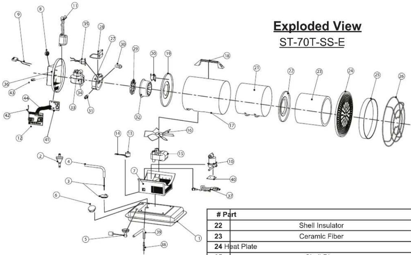
Parts List
| # Part | |
| 1 Fuel Tank Assembly | |
| 2 Fuel Filter | |
| 3 Fuel Pipe Assembly | |
| 4 Fuel Hose | |
| 5 Fuel Gauge | |
| 6 Fuel cap | |
| 7 Cooling Fan Housing | |
| 8 Control Knob | |
| 9 Power Switch wire Assembly | |
| 10 Electronic Pump | |
| 11 Igniter | |
| 12 | Main PCB with Thermostat |
| 13 Tip Over Sensor | |
| 14 | Tip over Sensor Wire Assembly |
| 15 | Motor |
| 16 | Plastic Fan Blade |
| 17 | Outer Shell |
| 18 | Handle |
| 19 | Burner Body Supporter |
| 20 | Temperature Limit Control |
| 21 Chamber Insulator | |
| # Part | |
| 22 | Shell Insulator |
| 23 | Ceramic Fiber |
| 24 Heat Plate | |
| 25 | Shell Ring |
| 26 | Safety Guard |
| 27 | Burner Body |
| 28 | Spark Plug |
| 29 | Burner Blade |
| 30 | Nozzle |
| 31 | Nipple |
| 32 | Diffusion cap |
| 33 | Blower Motor |
| 34 | Blower Housing / Air Guide / Blower Wheel (internal parts) |
| 35 | Photocell |
| 36 | Back Cover |
| 37 Power Cord | |
| 38 Return Pipe | |
| 39 | Return Hose |
| 40 | Pump Bracket |
| 41 | Display PCB |
| 42 | Thermistor |
| 43 | Power Switch |
| 44 | PCB cable |
| - | Back Panel (not shown) |
| - | Pump Connector (not shown) |
| - | Inlet Tube Assembly (not shown) |
| - | Hose Clamp (not shown) |
NEVER LEAVE HEATER UNATTENDED WHILE BURNING OR WHILE CONNECTED TO A POWER SOURCE
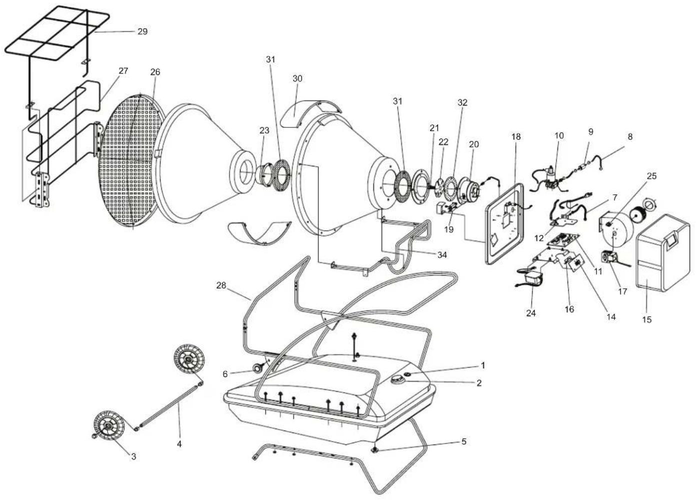
Exploded View
ST-125-OFR-E
NEVER LEAVE HEATER UNATTENDED WHILE BURNING OR WHILE CONNECTED TO A POWER SOURCE
Parts List: ST-125-OFR-E
| 1 Fuel Filter | |
| 2 Fuel Cap | |
| 3 Wheel | |
| 4 Axle | |
| 5 Drain Bolt | |
| 6 Height Adjustment Knob | |
| 7 Return Fuel Line | |
| 8 Intake Fuel Line | |
| 9 Fuel Filter Assembly | |
| 10 Fuel Pump | |
| 11 Main PCB and Fuse | |
| 12 Tip Over Sensor | |
| 13 Power Cord | |
| 14 Power Switch | |
| 15 Back Cover | |
| 16 Panel Sub-PCB | |
| 17 Blower Motor Assembly | |
| 18 Photocell | |
| 19 Spark Plug | |
| 20 Burner Body | |
| 21 Nozzle | |
| 22 Burner Blade | |
| 23 Diffusion Cap | |
| 24 Ignitor | |
| 25 Temperature Overheat Sensor | |
| 26 Heat Plate | |
| 27 Safety Guard | |
| 28 Front Frame | |
| 29 Top Safety Guard | |
| 30 Radiant Visors | |
| 31 Radiant Cone Gaskets | |
| 32 Burner Housing Assembly | |
NEVER LEAVE HEATER UNATTENDED WHILE BURNING OR WHILE CONNECTED TO A POWER SOURCE
Information requirements for liquid fuel local space heaters
| Model(s): ST-70-SS-E | ||||||||
| Indirect heating functionality: No | ||||||||
| Direct heat output: 20,5 (kW) | ||||||||
| Indirect heat output: N/A (kW) | ||||||||
| Fuel Diesel/Paraffin | Space heating emissions (*) | |||||||
| NOx | ||||||||
| Select fuel type | Liquid | 126.94 mg/kWh | ||||||
| Item | Symbol | Value | Unit | Item | Symbol | Value | Unit | |
| Heat output | Useful efficiency (NCV) | |||||||
| Nominal heat output | Pnom 20,5 kW | Useful efficiency at nominal heat output | η_th,nom 88,9 % | |||||
| Minimum heat output (indicative) | Pmin N/A kW | Useful efficiency at minimum heat output (indicative) | η_th,min N/A % | |||||
| Auxiliary electricity consumption | Type of heat output/room temperature control (select one) | |||||||
| At nominal heat output | e_max | 0,087 | kW | single stage heat output, no room temperature control | Yes | |||
| At minimum heat output | e_min | N/A kW | two or more manual stages, no room temperature control | No | ||||
| In standby mode | e_SB | N/A | kW | with mechanic thermostat room temperature control | No | |||
| with electronic room temperature control | No | |||||||
| with electronic room temperature control plus day timer | No | |||||||
| With electronic room temperature control plus week timer | No | |||||||
| Other control options (multiple selections possible) | ||||||||
| room temperature control, with presence detection | No | |||||||
| room temperature control, with open window detection | No | |||||||
| with distance control option | No | |||||||
| with adaptive start control | No | |||||||
| with working time limitation | No | |||||||
| with black bulb sensor | No | |||||||
| Permanent pilot flame power requirement | ||||||||
| Pilot flame power requirement (if applicable) | P_pilot | N/A | kW | |||||
| Contact details | Obelis S.A Bd. General Wahis, 53 1030 Brussels, Belgium | |||||||
| (*) NOx = nitrogen oxides | ||||||||
This product is not suitable for main heating purposes.
NEVER LEAVE HEATER UNATTENDED WHILE BURNING OR WHILE CONNECTED TO A POWER SOURCE
Information requirements for liquid fuel local space heaters
| Model(s): ST-70T-SS-E | ||||||||
| Indirect heating functionality: No | ||||||||
| Direct heat output: 20,5 (kW) | ||||||||
| Indirect heat output: N/A (kW) | ||||||||
| Fuel Diesel/Paraffin | Space heating emissions (*) | |||||||
| NOx | ||||||||
| Select fuel type | Liquid | 126.94 mg/kWh | ||||||
| Item | Symbol | Value | Unit | Item | Symbol | Value | Unit | |
| Heat output | Useful efficiency (NCV) | |||||||
| Nominal heat output | Pnom 20,5 kW | Useful efficiency at nominal heat output | _th,nom 90,9 % | |||||
| Minimum heat output (indicative) | Pmin N/A kW | Useful efficiency at minimum heat output (indicative) | _th,min N/A % | |||||
| Auxiliary electricity consumption | Type of heat output/room temperature control (select one) | |||||||
| At nominal heat output | e_max | 0,087 | kW | single stage heat output, no room temperature control | No | |||
| At minimum heat output | e_min | N/A kW | two or more manual stages, no room temperature control | No | ||||
| In standby mode | e_SB | N/A | kW | with mechanic thermostat room temperature control | Yes | |||
| with electronic room temperature control | No | |||||||
| with electronic room temperature control plus day timer | No | |||||||
| With electronic room temperature control plus week timer | No | |||||||
| Other control options (multiple selections possible) | ||||||||
| room temperature control, with presence detection | No | |||||||
| room temperature control, with open window detection | No | |||||||
| with distance control option | No | |||||||
| with adaptive start control | No | |||||||
| with working time limitation | No | |||||||
| with black bulb sensor | No | |||||||
| Permanent pilot flame power requirement | ||||||||
| Pilot flame power requirement (if applicable) | P_pilot | N/A | kW | |||||
| Contact details | Obelis S.A Bd. General Wahis, 53 1030 Brussels, Belgium | |||||||
| (*) NOx = nitrogen oxides | ||||||||
This product is not suitable for main heating purposes.
NEVER LEAVE HEATER UNATTENDED WHILE BURNING OR WHILE CONNECTED TO A POWER SOURCE
Information requirements for liquid fuel local space heaters
| Model(s): ST-125-OFR-E | ||||||||
| Indirect heating functionality: No | ||||||||
| Direct heat output: 36,6 (kW) | ||||||||
| Indirect heat output: N/A (kW) | ||||||||
| Fuel Diesel/Paraffin | Space heating emissions (*) | |||||||
| NOx | ||||||||
| Select fuel type | Liquid | 118,2 mg/kWh | ||||||
| Item | Symbol | Value | Unit | Item | Symbol | Value | Unit | |
| Heat output | Useful efficiency (NCV) | |||||||
| Nominal heat output | Pnom 36,6 kW | Useful efficiency at nominal heat output | η_th,nom 90,5 % | |||||
| Minimum heat output (indicative) | Pmin 27,8 kW | Useful efficiency at minimum heat output (indicative) | η_th,min N/A % | |||||
| Auxiliary electricity consumption | Type of heat output/room temperature control (select one) | |||||||
| At nominal heat output | e_max | 0,084 | kW | single stage heat output, no room temperature control | No | |||
| At minimum heat output | e_min | 0,075 kW | two or more manual stages, no room temperature control | Yes | ||||
| In standby mode | e_SB | N/A | kW | with mechanic thermostat room temperature control | No | |||
| with electronic room temperature control | No | |||||||
| with electronic room temperature control plus day timer | No | |||||||
| With electronic room temperature control plus week timer | No | |||||||
| Other control options (multiple selections possible) | ||||||||
| room temperature control, with presence detection | No | |||||||
| room temperature control, with open window detection | No | |||||||
| with distance control option | No | |||||||
| with adaptive start control | No | |||||||
| with working time limitation | No | |||||||
| with black bulb sensor | No | |||||||
| Permanent pilot flame power requirement | ||||||||
| Pilot flame power requirement (if applicable) | P_pilot | N/A | kW | |||||
| Contact details | Obelis S.A Bd. General Wahis, 53 1030 Brussels, Belgium | |||||||
| (*) NOx = nitrogen oxides | ||||||||
This product is not suitable for main heating purposes.
STANLEY®
SERVICE
| Belgique et Luxemburg | E. Walschaertstraat 142800 MechelenBelgium | www.stanleyworks.beEnduser.be@SBDinc.comBE-NL=+32 15 47 37 65BE-FR=+32 15 47 37 64BE Fax: +32 15 47 37 100 | United Kingdom | 210 Bath Road; Slough, Berks SL1 3YD | www.stanleytools.co.ukTel: +44 (0)1753 511234Fax: +44 (0)1753 512365 |
| Hungary Rotel Kft. | 1163 Budapest,Thököly ut 17. | www.stanleyworks.huservice@rotelkft.huTel: +36 1 404-0014Fax: +36 1 403-2260 | |||
| Danmark Roskildevej 22 | 2620 Albertslund | www.stanleyworks.dkkundeservice.dk@sbdinc.comFax: 70224910 | |||
| Deutschland Richard Klinger Str. 1165510 Idstein | www.stanleyworks.deinfo@sbdinc.deTel: 06126-21-1Fax: 06126-21-2770 | Czech Republic | BAND SERVIS CZ s.r.o.K Pasekam 4440760 01 Zlín, Czech Republic | ||
| Slovakia | BAND SERVIS s.r.o.Paulinska 22917 01 Trnava, Slovakia | ||||
| Poland Erpatech | ul. Bakaliowa 2605-080 Mościska | ||||
| Eλλάς Ημερος Τόπος 2 - Χανι Αδάμ Ασπρόπυργος-19300 -Αττική - Αττικής | www.stanley.grGreece.Service@sbdinc.comTηλ: +30 210 8985208Φαξ: +30 210 5597598 | ||||
| España Parque de Negocios “Mas Blau”Edificio Muntadas, c/Bergadá, 1, Of. A608820 El Prat de Llobregat (Barcelona) | www.stanleyworks.esrespuesta.postventa@sbdinc.comTel: 934 797 400Fax: 934 797 419 | Slovenia | G-M&M d.o.o.Brvace 111290 Grosuplje Slovenija | ||
| France 5, allée des hêtres | BP 30084, 69579 Limonest Cedex | www.stanleyoutillage.frscufr@sbdinc.comTel: 04 72 20 39 77Fax: 04 72 20 39 00 | Cyprus IOANNOU J. | ioannou.ioannis@cytanet.com.cyTel: +357 22344302Fax: +357 22348098 | |
| SchweizSuisseSvizzera | In der Luberzen 428902 Urdorf | www.stanleyworks.chverkaufch.sbd@sbdinc.comTel: 044 - 755 60 70Fax: 044 - 730 70 67 | Bosnia-Herzegovina | G-M&M d.o.o.Brvace 111290 GrosupljeSlovenija | |
| Ireland 210 Bath Road; Slough, Berks SL1 3YD UK www.stanleytools.co.uk | Tel: +44 (0)1753 511234Fax: +44 (0)1753 512365 | Bulgaria | TASHEV-GALVING LTD68 KLIMENT OHRIDSKI BLVD.1756 Sofia, Bulgaria | ||
| Italia Energypark-Building 03 sud, Via Energy Park6 20871 Vimercate (MB) | www.stanley.itTel: 039-9590-200Fax 039-9590-313 | Croatia G-M&M d.o.o.Brvace 111290 GrosupljeSlovenija | www.g-mm.sigmm@g-mm.siT: +386 01 78 66 500F: +386 01 78 63 023 | ||
| Nederlands Stanley Black & Decker Netherlands B.V.Postbus 836120 AD Born | www.stanleyworks.nlEnduser.NL@SBDinc.comTel: +31 164 28 30 63NL Fax: +31 164 28 32 00 | Estonia | AS TallmacMustame tee 44,EE-10621 Tallinn | ||
| Norge Postboks 4613, Nydalen0405 Oslo | www.stanleyworks.nokundeservice.no@sbdinc.comFax: 45 25 08 00 | Latvia LIC GOTUS SIA | www.licgotus.lvT: +371 67556949F: +371 67555140 | ||
| Österreich Oberlaerstrasse 248A-1230 Wien | www.stanleyworks.deservice.austria@sbdinc.comTel: 01 - 66116 - 0Fax: 01 - 66116 - 14 | Lithuania | UAB ELREMTA OUNeries kr. 16ELT - 48402 Kaunas | ||
| Portugal Quinta da Fonte - Edificio Q55 D. DinizRua dos Malhíes, 2 e 2A - Piso 2 Esquerdo2770 - 071 Paço de Arcos | www.stanleyworks.ptresposta.posvenda@sbdinc.comTel: 214 66 75 00Fax: 214 66 75 75 | Malta | Energypark-Building 03 sud, Via Energy Park6 20871 Vimercate (MB) | ||
| Suomi PL 47 | 00521 Helsinki | www.stanleyworks.ficustomerservice.fi@sbdinc.comPuh: 010 400 4333 | Romania | Stanley Black & DeckerPhoenicia Business CenterStrada Turturelelor, nr 11A, Etaj 6, Modul 15,Sector 3 Bucuresti | |
| Sverige | Box 94431 22 Mölndal | www.stanleyworks.sekundservice.se@sbdinc.comFax: 31 68 60 08 | Serbia G-M&M d.o.o.Brvace 111290 GrosupljeSlovenija | www.g-mm.sigmm@g-mm.siT: +386 01 78 66 500F: +386 01 78 63 023 | |
STANLEY®
Manufactured by:
Pinnacle Climate Technologies, Inc.
Sauk Rapids, MN 56379 USA
EC REP
Obelis S.A
Registered Address:
© 2021 Stanley Black & Decker, Inc.


- LAAT DE KACHEL NOOIT ONBEWAAKT ACHTER MET DE STEKKER IN HET STOPCONTACT
- Montage-instructies
- ST-125-OFR-E
- Montage
- Onderdelenlijst
- STANLEY®
- Numéros de modèles
- ST-70-SS-E / ST-70T-SS-E / ST-125-OFR-E
- NE JAMAIS LAISSER LE RADIATEUR SANS SURVEILLANCE LORSQU'IL EST BRANCHÉ À UNE SOURCE D'ALIMENTATION.
- Modellnummern
- DRUCKEINSTELLUNG:
- Teileliste
- Modelos
- NUNCA DEIXAR O AQUECEDOR SEM VIGILÂNCIA QUANDO LIGADO A UMA FONTE DE ENERGIA
- Montagem
- CÉLULA FOTOELÉTRICA:
- Lista de peças
- COMBUSTIBLE Y DEPÓSITO DE COMBUSTIBLE:
- ADVERTENCIA
- AJUSTES DE PRESIÓN:
- CÉLULA FOTOELECTRICA
- Numery modeli
- ST-70-SS-E/ST-70T-SS-E/ST-125-OFR-E
- Uchwyt przenośny
- NIGDY NIE POZOSTAWIAĆ BEZ NADZORU PROMIENNIKA PODŁĄCZONEGO DO ZASILANIA
- Instrukcja montażu
- Montaż
- Model Numbers
- DANGER
- GENERAL HAZARD WARNING:
- READ AND UNDERSTAND ALL OF THE INSTRUCTIONS IN THIS MANUAL
- ▲ DANGER
- NOT FOR USE IN RESIDENTIAL LIVING AREAS OR IN ENCLOSED SPACES WITHOUT ADEQUATE VENTILATION. FOR OUTDOOR USE. INDOOR USE
- NEVER LEAVE HEATER UNATTENDED WHILE BURNING OR WHILE CONNECTED TO A POWER SOURCE
- Table Of Contents
- Safety Information
- ▲ WARNING
- ▲WARNING
- RISK OF INDOOR AIR POLLUTION!
- CARBON MONOXIDE POISONING MAY LEAD TO DEATH!
- Headache • Dizziness • Nausea • Dry Mouth Sore Throat • Burning of Nose and Eyes
- RISK OF ELECTRIC SHOCK!
- RISK OF BURNS, FIRE AND EXPLOSION!
- WARNING
- KEEP CHILDREN, ANIMALS, CLOTHING AND COMBUSTIBLES AWAY FROM HEATER.
- Features
- Assembly Instructions
- ST-70-SS-E / ST-70T-SS-E
- Carry Handle Assembly
- Tools Needed:
- Assembly
- Operation
- Fueling The Heater:
- Paraffin
- CAUTION
- Ventilation:
- Starting the Heater: (Ignition)
- Stopping the Heater: (Cool Down)
- Restarting the Heater:
- Electrical Outlet (ST-70T-SS-E Only):
- Maintenance: ST-70-SS-E / ST-70T-SS-E / ST-125-OFR-E
- Long Term Storage:
- Service:
- FUEL / FUEL TANK:
- SPARK PLUG:
- FAN BLADES:
- PRESSURE ADJUSTMENTS:
- Service (Continued):
- NOZZLES:
- PHOTOCELL:
- FILTERS:
- NEVER LEAVE HEATER UNATTENDED WHILE BURNING OR
- WHILE CONNECTED TO A POWER SOURCE
- Wiring Diagrams
- Part
- Exploded View
Brand : STANLEY
Model : STN70SD
Category : Heating