
ST-70T-KFA-ES - Heating STANLEY - Free user manual and instructions
Find the device manual for free ST-70T-KFA-ES STANLEY in PDF.


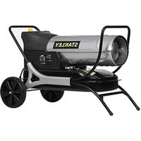
| Product Type | Direct-Fired, Forced Air Heater |
| Brand | Stanley |
| Model | ST-70T-KFA-ES |
| Thermal Power | 20 kW |
| Heating Area | 391 m² |
| Fuel Consumption | 1.9 L/h |
| Fuel Tank Capacity | 18 L |
| Max Operating Hours | 9.5 h |
| Voltage / Frequency | 220-240 V ~ 50 Hz |
| Motor Amps | 0.8 A |
| Motor Phase | Single |
| Heater Heat Output (Flame Temp) | 800 °C |
| Airflow | 550 CMH |
| Pump Pressure | 4 PSI |
| Operating Ambient Temperature | -25°C to 65°C |
| Dimensions (W x D x H) | 80 x 32 x 43 cm |
| Weight | 14.5 kg |
| Allowed Fuel Types | Paraffin / Diesel (1-K Kerosene, No.1 & No.2 Diesel, JP8/Jet A, No.1 & No.2 Fuel Oil) |
| Power Input | 230 W |
| Minimum Clearance (Top / Sides / Front) | 2 m / 2 m / 3.5 m |
| Safety Features | Overheat protection (temperature limit sensor), flame-out sensor, electronic ignition, thermostat control |
| Maintenance | Air filter cleaning every 500h, nozzle cleaning, spark plug gap 3.5mm, fuel tank flushing every 200h |
| Ventilation Requirement | Minimum 2800 cm² opening per 29.3 kW |
Frequently Asked Questions - ST-70T-KFA-ES STANLEY
User questions about ST-70T-KFA-ES STANLEY
0 question about this device. Answer the ones you know or ask your own.
Ask a new question about this device
Download the instructions for your Heating in PDF format for free! Find your manual ST-70T-KFA-ES - STANLEY and take your electronic device back in hand. On this page are published all the documents necessary for the use of your device. ST-70T-KFA-ES by STANLEY.
USER MANUAL ST-70T-KFA-ES STANLEY
natural_image
Two Stanley industrial heaters displayed side by side, no visible text or symbols on the device body.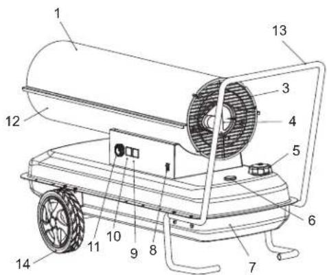
Pinnacle Climate Technologies, Inc.
Sauk Rapids, MN 56379 USA
EC REP
Obelis S.A
Registered Address:
© 2024 Stanley Black & Decker, Inc.
STANLEY.
STANLEY
natural_image
Two Stanley industrial heaters displayed side by side, no visible text or symbols on the device body.NEVER LEAVE HEATER UNATTENDED WHILE BURNING, OR WHILE CONNECTED TO A POWER SOURCE.
CE

EAC


This product is not suitable for primary heating purposes.
GB
PLEASE READ THE FOLLOWING INSTRUCTIONS CAREFULLY BEFORE USING THE APPLIANCE.
- This appliance can be used by children aged from 8 years and above and persons with reduced physical, sensory or mental capabilities or lack of experience and knowledge if they have been given supervision or instruction concerning use of the appliance in a safe way and understand the hazards involved. Children shall not play with the appliance. Cleaning and user maintenance shall not be made by children without supervision.
- Children of less than 3 years should be kept away unless continuously supervised. Children aged from 3 years and less than 8 years shall only switch on/off the appliance provided that it has been placed or installed in its intended normal operating position and they have been given supervision or instruction concerning use of the appliance in a safe way and understand the hazards involved. Children aged from 3 years and less than 8 years shall not plug in, regulate and clean the appliance or perform user maintenance.
- CAUTION: Some parts of this product can become very hot and cause burns. Particular attention has to be given where children and vulnerable people are present.
- If the supply cord is damaged, it must be replaced by the manufacturer, its service agent or similarly qualified persons in order to avoid a hazard.
- The heater must not be located immediately below a socket-outlet.
- Do not use this heater in the immediate surroundings of a bath, a shower or a swimming pool.
- This heater is filled with a precise quantity of special oil. Repairs requiring opening of the oil container are only to be made by the manufacturer or his service agent who should be contacted if there is an oil leak.
- When scrapping the heater, follow the regulations concerning the disposal of oil. Do not dispose of the heater in household waste and recycle the heater where local facilities exist for electrical goods and oil
- Place the appliance on a flat, stable, heat-resistant surface. Operating the product in any other position could cause a hazard.
- There may be trace of odour during the first few minutes of initial use. This is normal and will quickly disappear.
- Do not attempt to repair, disassemble or modify the appliance. There are no user-serviceable parts inside.
- CAUTION: if using an extension lead please ensure you do not exceed the maximum rated running wattage/load of the extension lead.

Read The Instruction manual: When this symbol is marked on a product, it means that the instruction manual must be read.

WARNING! Never touch heater until heater has cooled off.

GB
This appliance can be used by children aged from 8 years and above and persons with reduced physical, sensory or mental capabilities or lack of experience and knowledge if they have been given supervision or instruction concerning use of the appliance in a safe way and understand the hazards involved. Children shall not play with the appliance. Cleaning and user maintenance shall not be made by children without supervision.
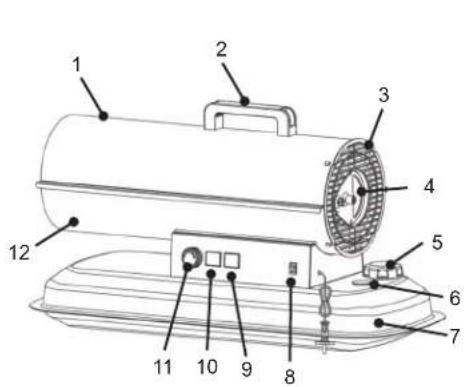
ST-70T-KFA-ES ST-125T-KFA-ES

-
Upper Cover
-
Handle
-
Rear Grill
-
Motor Air Pump Assembly
-
Fuel Tank Cover
-
Fuel Meter
-
Fuel Tank
-
Power Switch
-
Room Temp
-
Set Temp
-
Temperature Knob
-
Bottom Cover
-
Pipe Rack
-
Castor
SPECIFICATIONS
Specifications subject to change without notice
| Model # ST-70T-KFA-ES ST-125T-KFA-ES | ||
| HEATING AREA (m ^2 ) 391 698 | ||
| THERMAL POWER (kW) 20 36 | ||
| FUEL CONSUMPTION (L/H) 1.9 3.4 | ||
| TANK CAPACITY (L) 18 38 | ||
| MAX OPERATING HOURS 9.5 11.1 | ||
| VOLTAGE (V) / FREQUENCY (Hz) 220-240V~50HZ 220-240V~50HZ | ||
| MOTOR AMPS | 0.8 0.8 | |
| MOTOR PHASE | SINGLE | SINGLE |
| HEATER HEAT OUTPUT (°C) | 800 800 | |
| AIRFLOW (CMH) | 550 600 | |
| PUMP PRESSURE (PSI) | 4 | 4.8 |
| MINIMUM/MAXIMUM RECOMMENDED OPERATING AMBIENT TEMPERATURE | -25°C/65°C | -25°C/65°C |
| PRODUCT DIMENSIONS (cm) | 80 x 32 x 43 | 102 x 50 x 67 |
| HEATER WEIGHT (Kg) | 14.5 | 20.3 |
| ALLOWED FUEL TYPES | Paraffin/Diesel | Paraffin/Diesel |
| POWER INPUT (W) | 230 230 |
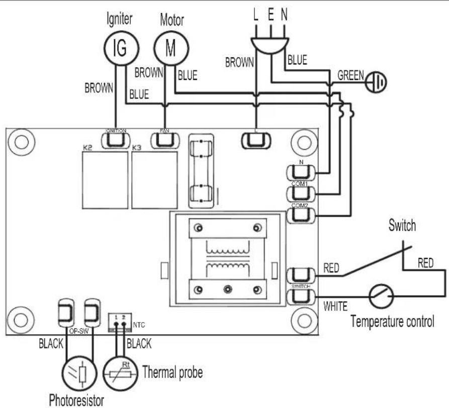
WIRING DIAGRAM
Safety Information
This is a parafin, direct-fired, forced air heater. It is primarily intended for use for temporary heating of buildings under construction, alteration or repair. This appliance produces small amounts of carbon monoxide. WARNING! Risk of indoor air pollution! Use this heater only in well ventilated areas! Provide at least a 2,800 sq cm opening of outside air for every 29,3 kw/hr or 100,000 BTU/hr of heater rating. Provide a larger opening if more heaters are being used.
DANGER
Carbon Monoxide poisoning may lead to death!
WARNING
Risk of burns / fire / explosion! NEVER use fuel such as gasoline, benzene, alcohol,
white gas, camp stove fuel, paint thinners, or other oil compounds in this heater (THESE ARE VOLATILE FUELS THAT CAN CAUSE A FIRE OR EXPLOSION).
⚠ WARNING Fire, burn, inhalation, and explosion hazard. Keep combustibles a safe distance away from the heater as recommended by these instructions. Never use the heater in spaces which contain products such as gasoline, solvents, paint thinners, dust particles, volatile or airborne combustibles, or any unknown chemicals. This is an unvented portable heater. It uses air (oxygen) from the area in which it is used. Adequate combustion and ventilation air must be provided.
⚠ WARNING Do not operate this heater until you have read, and thoroughly understand these safety and operating instructions. Failure to comply with the precautions and instructions provided with this heater can result in death, serious bodily injury, property loss or damage from the hazards of fire, soot production, explosion, burns, asphyxiation or carbon monoxide poisoning. Only persons who can read and understand these instructions should use or service this heater. Retain this manual for your reference.
Minimum clearance from Combustibles:
ST-70T-KFA-ES / ST-125T-KFA-ES
Top 6.5 ft / 2m
Sides 6.5 ft / 2m
Front 11.4 ft / 3.5m
- NEVER refill the heater's fuel tank while heater is operating or still hot. This heater is EXTREMELY HOT while in operation.
- Keep all combustible materials away from this heater.
- NEVER block air inlet (rear) or air outlet (front) of heater.
- NEVER use duct work in front or at rear of heater.
- NEVER move or handle heater while still hot.
- NEVER transport heater with fuel in its tank.
- If equipped with a thermostat, the heater may start at any time.
- ALWAYS locate heater on a stable and level surface.
- ALWAYS keep children and animals away from heater.
- Bulk fuel storage should be a minimum of 7.6m (25 ft). from heaters, torches, portable generators, or other sources of ignition.
- ALWAYS unplug the heater when not in use.
- Not for use in homes or recreational vehicles.
- Never use this heater in living or sleeping areas.
- NEVER use heater where flam mable vapors may be present.
- Use only the electrical power (voltage and frequency) specified on the model plate of the heater.
- ALWAYS install the heater so that it is not directly exposed to water spray, rain, dripping water, or wind.
- NEVER store fuel in direct sunlight, indoors, or near a source of heat.
- NEVER use fuel that has been stored from one season to the next. Fuel deteriorates over time. OLD FUEL WILL NOT BURN PROPERLY IN THIS HEATER.
Assembly
MODEL ST-70T-KFA-ES
- Tools required: Medium phillips screw driver.
- Remove the 2 screws on the upper cover.
- Align the holes in the upper housing with the 2 holes in the handle.
- Insert and tighten screws securely with screw driver.
MODEL ST-125T-KFA-ES (Figure 1)
- Tools required: Medium phillips screw driver, 8mm open end or adjustable wrench, needle nose pliers.
- Put the caster bracket I under the fuel tank C and lock it with M5*12 screw J and M5 nut D, insert the caster shaft K into the caster bracket I and fix it with the positioning pin (as shown in the picture).
- Insert the caster H and gasket G into the caster shaft K and lock it with M8 nuts F, and install the caster cover E.
- Put the pipe rack A under the fuel tank C and lock it with M5*35 screw B and M5 nut D.

A. Pipe rack
E. Caster wheel cover
I. Caster bracket
B. M5*35 screw
F. M8 lock nut
J. M5*12 screw
C. Fuel tank
G. M8 gasket
K. Caster shaft
D. M5 lock nut
H. Caster
Figure 1. Handle Assembly
▲WARNING NEVER REFUEL THIS HEATER WHILE IT IS HOT OR OPERATING. FIRE OR EXPLOSION COULD RESULT.
▲CAUTION NEVER FILL THE FUEL TANK INDOORS. ALWAYS FILL THE TANK OUTDOORS. BE SURE THAT THE HEATER IS ON LEVEL GROUND WHEN FUELING, AND NEVER OVERFILL THE FUEL TANK.
Operation
This heater is factory-tested for use with 1-K kerosene/paraffin, no. 1 & no. 2 diesel, JP8/Jet A Fuel, and no. 1 & no. 2 fuel oil.
TO START THE HEATER:
- Fill the tank with paraffin until fuel gauge points to "F".
- Be sure fuel cap is secure.
- Plug power cord into electrical outlet.
- Turn thermostat control knob to desired temperature setting. The setting range is from 0°C to 65°C. Push the Power switch to the "l" position.
Optimum pressure occurs when the nose cone is cherry red and there are no extending flames from the heater.
NOTE: The room temperature display will indicate the following: -Between -9 ° and 99°C display shows actual temperature.
TO STOP THE HEATER: Turn the Temp. Setting Knob to left, turn the Power Switch to "O" position, and unplug the Power Cord.
TO RESTART THE HEATER
- Wait ten seconds after shutting off heater.
- Turn the Power Switch to "l" position.
- Be sure to follow all starting procedure precautions.
LONG TERM STORAGE
Drain Fuel Tank
- For models ST-70T-KFA-ES, drain fuel through the fuel cap opening using an approved siphon. For models ST-125-KFA-ES, drain fuel through the Drain Plug at the bottom of the Fuel Tank.
- To remove the Drain Plug (125), pull the Plug Grip downward and remove seal head from drain hole in tank.
- Rinse and completely empty the tank.
- To replace, push the drain head fully into the drain hole and secure by pushing the seal cap fully into the head hole.
IMPORTANT: Never store leftover fuel over the summer. Using old fuel can damage your heater
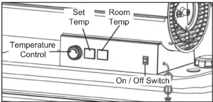
Figure 2. Start The Heater
Store heater in a dry, well-ventilated area! If your heater cannot be stored indoors, a tarp or weatherproof cover must be used to protect the heater.
Be sure that the storage area is free of dust and corrosive vapors. Repack the heater in the original shipping material. Keep the Users Manual in an easily accessible place.
Maintenance
Always service heater in a clean, flat, dry area. Never service heater while it is plugged in or while hot!
Never service heater in wet conditions. In an emergency, be sure heater has completely cooled before servicing using a tarp or weatherproof cover, to ensure heater or electronics
inside heater are not exposed to wet conditions. Do not service heater while plugged in under any circumstance.
FUEL/FUEL TANK: Flush every 200 hours of operation or as needed with paraffin.
AIR FILTERS: Open heater lid to access filters. Filters should be replaced every 500 hours of operation, or less, depending on conditions. See figure 7.1 on page 7 for detailed view.
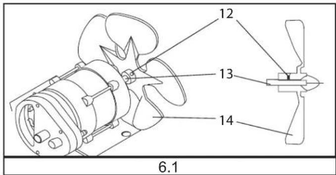
FAN BLADES: Open heater lid to access fan blades. Blades should be cleaned at least once per heating season. See figure 6.1 on page 7 for detailed view.
NOZZLES: Open heater lid and remove burner head to access nozzle. Nozzles should be cleaned or replaced at least once per heating season. See figure 3.1 on page 7 for detailed view.
SPARK PLUG: Open heater lid to access spark plug. Clean and re-gap every 600 hours of operation, or replace as needed.
Re-gap the terminals to 3.5mm. See figure 3.1 on page 7 for detailed view.
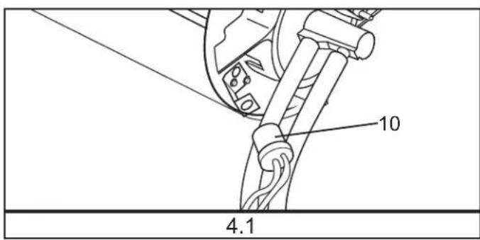
PHOTOCELL: Open heater lid to access photocell. The Photocell should be cleaned at least once per heating season or more depending on conditions. See figures 4.1 and 5.1 on page 7 for detailed view.
After servicing your heater you should perform the following function check before commissioning this heater:
- check the air and fuel lines for leaks using a 50/50 soap solution
- check extension cord for wear, cracks or cuts
- check to see igniter lines are connected securely to spark plug Improper maintenance can lead to poor combustion and soot production. Never alter or modify the heater. Use only genuine parts from the manufacturer or sales agent for repair and maintenance on your heater, and contact the manufacturer or sales agent before replacing parts other than those specified or recommended.
PUMP PRESSURE ADJUSTMENT:
While heater is operating, turn relief valve clockwise to increase, counterclockwise to decrease. Use flat blade screwdriver to turn valve. (Figure 3).
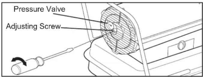
Figure 3. Adjust Pump Pressure
This appliance is not intended for use by persons (including children) with reduced physical, sensory or mental capabilities, or lack of experience and knowledge, unless they have been given supervision or instruction concerning use of the appliance by a person responsible for their safety. Children should be supervised to ensure that they do not play with the appliance.
If the power cord is damaged, it must be replaced by the manufacturer, its service agent or similarly qualified persons in order to avoid a hazard.
Plug Replacement
▲ WARNING RISK OF ELECTRIC SHOCK! DISCONNECT FROM POWER BEFORE MAINTENANCE.
NOTE: This section only applies to heaters sold or used in Great Britain.
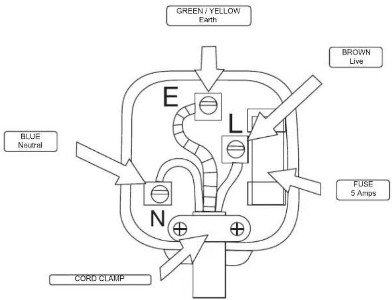
This appliance is supplied with a BS1363 3 pin plug fitted with a fuse. Should the fuse require replacement, it must be replaced with a fuse with the proper amp rating. (see Technical Specifications page 2) and approved to BS1362.
In the event the mains plug has to be removed/ replaced for any reason, please note:
The blue wire must be connected to the terminal marked with an N or colored black. The brown wire must be connected to the terminal marked with an L or colored red. The green/ yellow wire must be connected to the earthing terminal which is marked with an E or with the earth symbol.
IMPORTANT: The wires in the mains lead are colored in accordance with the following code:
Blue – Neutral Brown – Live
Green/Yellow – Earth
As the colors of the wires in the mains lead of this appliance may not correspond with the colored markings identifying the terminals in your plug, proceed as follows:
▲WARNING the plug.
Never connect live or neutral wires to the earth terminal of
NOTE: If a moulded plug is fitted and has to be removed take great care in disposing of the plug and severed cable, it must be destroyed to prevent engaging into a socket.
Plug Replacement Wiring Diagram
TROUBLESHOOTING GUIDE
| Problem Possible Cause Solution | ||
| Heater fires, but Main PCB shuts heater off after a short period of time. Display shows “E1” | Incorrect pump pressureDirty Input, Output or Lint FilterDirty Fuel FilterNozzle is DirtyPhotocell lens is DirtyPhotocell not installed properlyPhotocell DefectiveImproper electrical connection between Main PCB and Photocell | Adjust Pump PressureClean/replace Air FilterClean/replace Fuel FilterClean/replace NozzleClean/replace PhotocellAdjust Photocell positionReplace PhotocellCheck wiring connections (See Wiring Diagrams, Page 2) |
| Heater will not operate, or motor runs for short time. Display shows “E1” | No paraffin in fuel tankIncorrect pump pressureCorroded Spark Plug or incorrect plug gap.Dirty Fuel FilterDirty NozzleMoisture in Fuel/Fuel TankImproper electrical connection between Transformer and Circuit BoardIgnitor Wire not connected to Spark PlugDefective Ignitor | Fill tank with fresh paraffinAdjust Pump PressureClean/replace Spark PlugClean/replace Fuel FilterClean/replace NozzleRinse out fuel tank with clean fresh paraffinInspect all electrical connections. See Wiring Diagrams (Page 2)Re-attach Ignitor wire to Spark PlugReplace Ignitor |
| Fan does not operate when heater is plugged in and Power Switch is in the “ON” position. Display shows “E1” or “E2” | Thermostat is set too lowBroken electrical connection between Main PCB and motor | Rotate thermostat to a higher settingInspect all electrical connections. See Wiring Diagrams (Page 2) |
| Poor Combustion and / or excess soot production | Dirty Input, Output or Lint FilterDirty Fuel FilterPoor quality of fuelPSI is too high or too low | Clean/replace Air FilterClean/replace Fuel FilterBe sure fuel is not contaminated or oldUse proper pressure |
| Heater does not turn on and the lamp is not lit | Temperature limit sensor has overheatedNo electrical powerFuse BlownImproper electrical connection between Temperature Limit Sensor and Circuit Board | Push Power Switch to “OFF” and allow heater to cool for 10 minutes. Push Power Switch to back to “ON”Check power cord and extension cord to insure of proper connection. Test power supplyCheck/replace FuseInspect all electrical connections. Wiring Diagrams (Page 2) |
PART MAINTENANCE




GB
-
BURNER HEAD
-
SCREW
-
SPARK PLUG
-
IGNITOR WIRE
-
FUEL HOSE
-
AIR HOSE
-
NOZZLE
-
AIR LINE FITTING
-
FUEL LINE FITTING
-
PHOTOCELL
-
PHOTOCELL LENS
-
SET SCREW
-
MOTOR SHAFT
-
FAN BLADE
-
OUTPUT FILTER
-
INTAKE FILTER
-
END FILTER COVER
-
LINT FILTER
-
FUEL FILTER
20.PCB

| No. | PartNo.PartNo.PartNo.Part | ||||||
| 1 | Side Panel | 13 | Earth Tag | 25 | Insulated Barrel | 37 | Pump Core |
| 2 | Lower Cover | 14 | Control Panel | 26 | Upper Cover | 38 | Pump Body |
| 3 | Fuel Tank Assembly | 15 | Rotary Knob | 27 | Handle | 39 | Air Pump Cover |
| 4 | Insulated Bucket Support | 16 | Fuel Tank Cap | 28 | Fixed Tray of Stabilized Flame Plate | 40Air | Pump Gland Gasket |
| 5 | Inlet Pipe Gasket | 17 | Sealing Strip | 29 | Electric Eye Holder | 41 | Wool Felt |
| 6 | Fuel Inlet Pipe Filter | 18 | Display Cover | 30 | Electric Eye Component | 42 | Intake Filter Cotton |
| 7 | Inlet Pipe | 19 | Fuel Meter | 31 | Injection Nozzle | 43 | Air Pump Gland |
| 8 | Display Board | 20 | Switch | 32 | Stabilization Flame Plate | 44 | Pressure Regulating Hole Screw |
| 9 | High Voltage Wire Sheath | 21 | Motor Bracket | 33 | Bipolar Ignition Needle | 45 | Choke Plug |
| 10 | Ignition Transformer | 22 | Outlet Pipe Elbow | 34 | Fan | 46 | Rear Grill |
| 11 | Power Board | 23 | Mask Assembly | 35 | Motor | ||
| 12 | Holder | 24 | Combustion Barrel | 36 | Pump Blade |

| No. | PartNo.PartNo.PartNo.Part | ||||||
| 1 | Side Panel | 13 | Display Board | 25 | Outlet Pipe Elbow | 37 | Motor |
| 2 | Caster Wheel Shaft 14 | High Voltage Wire Sheath | 26 | Pipe Rack 38Pump Blade | |||
| 3 | Caster Support | 15 | Ignition Transformer | 27 | Combustion Barrel | 39 | Pump Core |
| 4 | Fuel Tank Assembly | 16 | Power Board | 28 | Insulated Barrel | 40 | Pump Body |
| 5 | Lower Cover | 17 | Holder | 29 | Upper Cover | 41 | Air Pump Cover |
| 6 | Caster | 18 | Earth Tag | 30 | Electric Eye Holder | 42 | Air Pump Gland Gasket |
| 7 | Fuel Meter | 19 | Control Panel | 31 | Electric Eye Component | 43 | Wool Felt |
| 8 | Insulation Shell Support | 20 | Rotary Knob | 32 | Injection Nozzle | 44 | Intake Filter Cotton |
| 9 | Fuel Tank Cover | 21 | Sealing Strip | 33 | Stabilization Flame Plate | 45 | Air Pump Gland |
| 10 | Oil Inlet Pipe Gasket | 22 | Display Cover | 34 | Bipolar Ignition Needle | 46 | Pressure Regulating Hole Screw |
| 11 | Oil Inlet Pipe Filter | 23 | Switch | 35 | Fan | 47 | Barometer |
| 12 | Inlet Pipe | 24 | Motor Bracket | 36 | Outlet Pipe Elbow | 48 | Rear Grill |
STANLEY®
SERVICE
| Belgique et LuxemburgBelgië en Luxembourg | E. Walschaertstraat 142800 MechelenBelgium | www.stanleyworks.beEnduser.be@SBDinc.comBE-NL= +32 15 47 37 65BE-FR = +32 15 47 37 64BE Fax: +32 15 47 37 100 |
| Danmark Roskildevej 22 | 2620 Albertslund | www.stanleyworks.dkkundeservice.dk@sbdinc.comFax: 70224910 |
| Deutschland Richard Klinger Str. 1165510 Idstein | www.stanleyworks.deinfo@sbdinc.deTel: 06126-21-1Fax: 06126-21-2770 | |
| Ελλάς Ημερος Τόπος 2 - Χάνι Αδάμ Ασπρόπυργος-19300 -Αττική - Αττικής | www.stanley.grGreece.Service@sbdinc.comΤηλ: +30 210 8985208@αξ: +30 210 5597598 | |
| España Parque de Negocios “Mas Blau”Edificio Muntadas, c/Bergadá, 1, Of. A608820 El Prat de Llobregat (Barcelona) | www.stanleyworks.esrespuesta.postventa@sbdinc.comTel: 934 797 400Fax: 934 797 419 | |
| France 5, allée des hêtres | BP 30084, 69579 Limonest Cedex | www.stanleyoullage.frscufr@sbdinc.comTel: 04 72 20 39 77Fax: 04 72 20 39 00 |
| SchweizSuisseSvizzera | In der Luberzen 428902 Urdorf | www.stanleyworks.chverkaufch.sbd@sbdinc.comTel: 044 - 755 60 70Fax: 044 - 730 70 67 |
| Ireland 210 Bath Road; Slough, Berks SL1 3YD UK www.stanleytools.co.uk | Tel: +44 (0)1753 511234Fax: +44 (0)1753 512365 | |
| Italia Energypark–Building 03 sud, Via Energy Park6 20871 Vimercate (MB) | www.stanley.itTel. 039-9590-200Fax 039-9590-313 | |
| Nederlands Stanley Black & Decker Netherlands B.V.Postbus 836120 AD Born | www.stanleyworks.nlEnduser.NL@SBDinc.comTel: +31 164 28 30 63NL Fax: +31 164 28 32 00 | |
| Norge Postboks 4613, Nydalen0405 Oslo | www.stanleyworks.nokundeservice.no@sbdinc.comFax: 45 25 08 00 | |
| Österreich Oberlaaerstrasse 248A-1230 Wien | www.stanleyworks.deservice.austria@sbdinc.comTel: 01 - 66116 - 0Fax: 01 - 66116 - 14 | |
| Portugal Quinta da Fonte – Edificio Q55 D. DinizRua dos Malhões, 2 e 2A – Piso 2 Esquerdo2770 - 071 Paço de Arcos | www.stanleyworks.ptresposta.posvenda@sbdinc.comTel: 214 66 75 00Fax: 214 66 75 75 | |
| Suomi PL 47 | 00521 Helsinki | www.stanleyworks.ficustomerservice.fi@sbdinc.comPuh: 010 400 4333 |
| Sverige | Box 94431 22 Mölndal | www.stanleyworks.sekundservice.se@sbdinc.comFax: 31 68 60 08 |
| United Kingdom | 210 Bath Road; Slough, Berks SL1 3YD | www.stanleytools.co.ukTel: +44 (0)1753 511234Fax: +44 (0)1753 512365 |
| Hungary Rotel Kft. | 1163 Budapest,Thököly út 17. | www.stanleyworks.hu service@rotelkft.huTel +36 1 404-0014Fax+36 1 403-2260 |
| Czech Republic | BAND SERVIS CZ s.r.o.K Pasekam 4440760 01 Zlín, Czech Republic | www.stanleyworks.czhttp://www.bandservis.czTel.: +420 577 008 550Fax.: +420 577 008 559 |
| Slovakia | BAND SERVIS s.r.o.Paulinska 22917 01 Trnava, Slovakia | www.bandservis.skTel.: +421 335 511 063Fax.: +421 335 512 624 |
| Poland | Erpatechul. Bakaliowa 2605-080 Mościska | www.stanleyworks.plTel.: +48 22 431 05 00Fax.: +48 22 468 87 35 |
| Slovenia | G-M&M d.o.o.Brvace 111290 Grosuplje Slovenija | www.g-mm.si gmm@g-mm.siT: +386 01 78 66 500F: +386 01 78 63 023 |
| Cyprus IOANNOU J. | 4A Ath.Diakou street1046-Nicosia-Cyprus | ioannou.ioannis@cytanet.com.cyTel: +357 22344302Fax: +357 22348098 |
| Bosnia-Herzegovina | G-M&M d.o.o.Brvace 111290 GrosupljeSlovenija | www.g-mm.si gmm@g-mm.siT: +386 01 78 66 500F: +386 01 78 63 023 |
| Bulgaria | TASHEV-GALVING LTD68 KLIMENT OHRIDSKI BLVD.1756 Sofia, Bulgaria | www.tashev-galving.comT: +359 2 700 45 45 4F: +359 (2) 439 21 12 |
| Croatia G-M&M d.o.o. | Brvace 111290 GrosupljeSlovenija | www.g-mm.si gmm@g-mm.siT: +386 01 78 66 500F: +386 01 78 63 023 |
| Estonia | AS TallmacMustame tee 44,EE-10621 Tallinn | www.tallmac.ee/estT: +372 6562999F: +372 6562855 |
| Latvia LIC GOTUS SIA | Ulbrokas Str.LT - 1021 Riga | www.licgotus.lvT: +371 67556949F: +371 67555140 |
| Lithuania | UAB ELREMTA OUNeries kr. 16ELT - 48402 Kaunas | info@elremta.ltT: +370-685-29035F: +370-37-406540 |
| Malta | Energypark-Building 03 sud, Via Energy Park 6 20871 Vimercate (MB) | www.stanley.itTel. 039-9590-200Fax 039-9590-313 |
| Romania | Stanley Black & DeckerPhoenicia Business CenterStrada Turturelelor, nr 11A, Etaj 6, Modul 15,Sector 3 Bucuresti | www.stanleyworks.roT: +4021.320.61.04/05F: +4037.225.36.84 |
| Serbia G-M&M d.o.o. | Brvace 111290 GrosupljeSlovenija | www.g-mm.si gmm@g-mm.siT: +386 01 78 66 500F: +386 01 78 63 023 |
STANLEY®
Manufactured by:
Pinnacle Climate Technologies, Inc.
Sauk Rapids, MN 56379 USA
EC REP
Obelis S.A
Registered Address:
© 2024 Stanley Black & Decker, Inc.
STANLEY.
STANLEY
STANLEY, The STANLEY Logo, The Notched Rectangle and the Yellow and Black Diagonal Package Design are all trademarks of Stanley Black & Decker, Inc. or an affiliate thereof.

- GB
- PLEASE READ THE FOLLOWING INSTRUCTIONS CAREFULLY BEFORE USING THE APPLIANCE.
- ST-70T-KFA-ES ST-125T-KFA-ES
- Safety Information
- DANGER
- Carbon Monoxide poisoning may lead to death!
- WARNING
- Minimum clearance from Combustibles:
- ST-70T-KFA-ES / ST-125T-KFA-ES
- Assembly
- MODEL ST-70T-KFA-ES
- MODEL ST-125T-KFA-ES (Figure 1)
- Operation
- TO START THE HEATER:
- TO RESTART THE HEATER
- LONG TERM STORAGE
- Drain Fuel Tank
- Maintenance
- PUMP PRESSURE ADJUSTMENT:
- Plug Replacement
- ▲ WARNING RISK OF ELECTRIC SHOCK! DISCONNECT FROM POWER BEFORE MAINTENANCE.
- ▲WARNING the plug.
- PART MAINTENANCE
- STANLEY®
- SERVICE
- EC REP
Brand : STANLEY
Model : ST-70T-KFA-ES
Category : Heating