
CCE60NXS - Range hood CANDY - Free user manual and instructions
Find the device manual for free CCE60NXS CANDY in PDF.
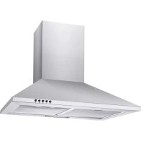



| Product type | Cooker hood |
| Brand | Candy |
| Model | CCE60NXS |
| Width | 60 cm |
| Recommended mounting height | 65 to 75 cm above the cooking surface |
| Power supply | 230 V ~ 50 Hz |
| Motor power | 120 W (estimated) |
| Number of speeds | 3 speeds + booster function |
| Lighting type | LED 1.5 W max |
| Grease filter type | Washable metal filter |
| Activated carbon filter | Optional for recirculation mode |
| Maximum airflow | 650 m³/h (estimated) |
| Maximum noise level | 65 dB (estimated) |
| Dimensions (W x D x H) | 60 x 50 x 45 cm (estimated) |
| Net weight | 15 kg (estimated) |
| Material | Stainless steel and glass |
| Control type | Illuminated push buttons |
| Booster function | Yes (5 minutes at maximum speed) |
| Grease filter maintenance | Monthly cleaning in dishwasher or by hand |
| Carbon filter maintenance | Annual replacement (if recirculation mode) |
| Insulation class | Class I (earthing mandatory) |
| Exhaust duct diameter | 150 mm |
| Repairability index | 5.0 (estimated) |
Frequently Asked Questions - CCE60NXS CANDY
User questions about CCE60NXS CANDY
0 question about this device. Answer the ones you know or ask your own.
Ask a new question about this device
Download the instructions for your Range hood in PDF format for free! Find your manual CCE60NXS - CANDY and take your electronic device back in hand. On this page are published all the documents necessary for the use of your device. CCE60NXS by CANDY.
USER MANUAL CCE60NXS CANDY
Zanagnutipanel model
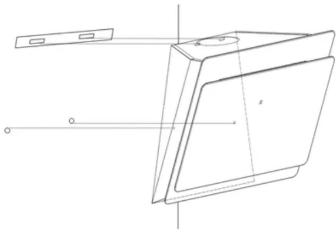
- It is necessary to drill 2x8mm additional holes and mounting screws and locking screws before installation.
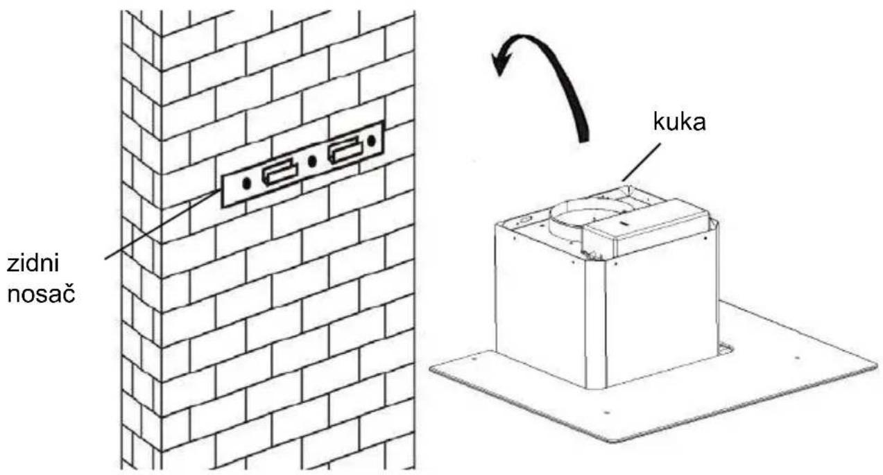
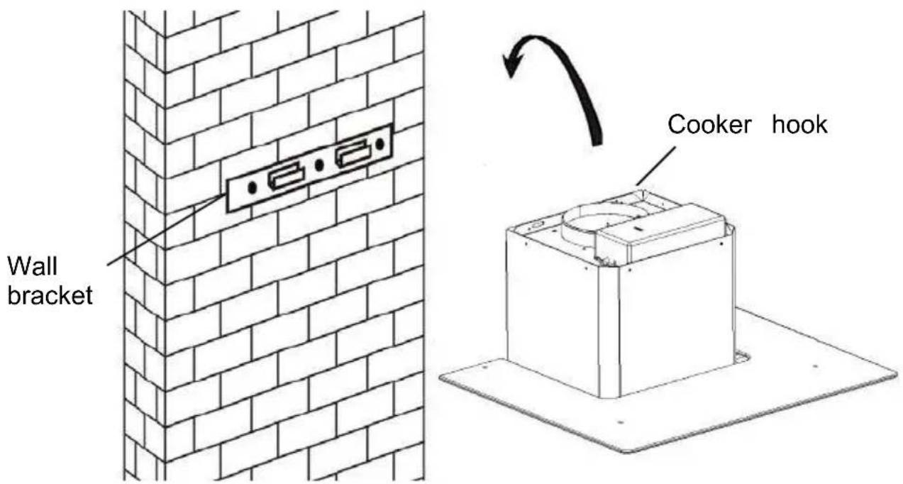
- Lift the hood and hang it on the wall bracket using the hook.
INSTALLATION AND USER'S MANUAL
CONTENT
INTRODUCTION 35
SAFETY PRECAUTION 35
SPECIFICATION 37
INSTALLATION (VENT OUTSIDE) 38
INSTALLATION (VENT INSIDE) 43
DESCRIPTION OF COMPONENTS 44
OPERATION 44
MAINTENANCE 47
TROUBLESHOOTING 48
CONFORMITY WITH DIRECTIVES 48
ENVIRONMENTAL PROTECTION 49
Thank you for choosing this cooker hood.
This instruction manual is designed to provide you with all required instructions related to the installation, use and maintenance of the appliance. In order to operate the unit correctly and safely, please read this instruction manual carefully before installation and usage.
The cooker hood uses high quality materials, and is made with a streamlined design. Equipped with a large power electric motor and centrifugal fan, it also provides strong suction power, low noise operation, and non-stick grease filters that are easy to assemble and install.

By placing the marking on this product, we declare, on our own responsibility, compliance to all European safety, health and environmental requirements stated in the legislation for this product.
SAFETY PRECAUTION
Never let children operate the machine.
The cooker hood is for home use only, not suitable for barbecue, shops, or other commercial purposes.
The cooker hood and its filter should be cleaned regularly in order to keep it in good working condition.
Clean the cooker hood according to the instruction manual and keep the unit from danger of burning.
Forbid direct baking from the gas cooker.
Please keep the kitchen room well ventilated.
Before connecting this appliance, check that the power supply cord is not damaged. A damaged supply cord must be replaced by qualified service personnel only.
There shall be adequate ventilation of the room when the range hood is used at the same time as appliances burning gas or other fuels.
The air must not be discharged into a flue that is used for exhausting fumes from appliances burning gas or other fuels.
Regulations concerning the discharge of air have to be fulfilled.
This appliance is not intended for use by persons (including children) with reduced physical, sensory or mental capabilities, or lack of experience and knowledge, unless they have been given supervision or instruction concerning use of the appliance by a person responsible for their safety.
Children should be supervised to ensure that they do not play with the appliance.
Do not flambé under the range hood.
CAUTION: Accessible parts may become hot when used with cooking appliances.
Electrical shock hazard.
Only plug this unit into a properly earthed outlet. If in doubt, seek advice from a suitably qualified engineer.
Failure to follow these instructions can result in death, fire, or electrical shock.
Electrical installation.
All installation must be carried out by a competent person or qualified electrician. Before connecting the mains supply, ensure that the mains voltage corresponds to the voltage on the rating plate.
Direct connection.
The appliance must be connected directly to the mains using an omnipolar circuit breaker with a minimum opening of 3 mm between the contacts.
The installer must ensure that the correct electrical connection has been made and that it complies with the wiring diagram.
The cable must not be bent or compressed.
Regularly check the power plug and power cord for damage. If the supply cord is damaged, it must be replaced by a special cord or assembly available from the manufacturer or its service agent.
WARNING: This is a Class I appliance and MUST be earthed
This appliance is supplied with a 3 core mains cable coloured as follows:
Brown = L or Live
Blue = N or Neutral
Green and Yellow = E or Earth
The fuse must be rated at 3 Amps.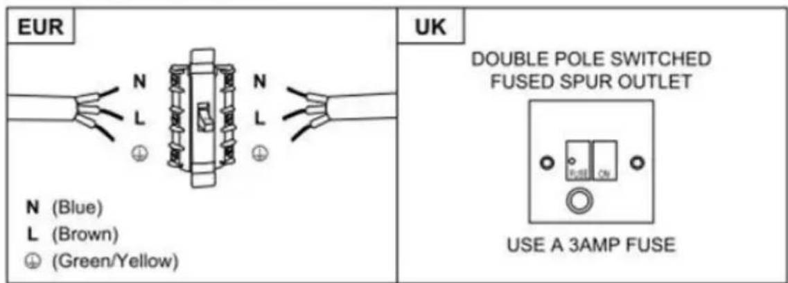
Standard Installation Accessories List
| Spec. | Illustration Picture | Qty |
| Casing | 1 | |
| Upper Chimney | 1 | |
| Lower Chimney | 1 | |
| Lower chimney bracket | 1 | |
| Upper chimney bracket | 1 | |
| Hanging Board | 1 | |
| φ8 rawl plugs φ8×φ6 white color | 9 | |
| Screws ST4.0×30 | 9 | |
| φ7.2screws ST4.0×8 | 2 |
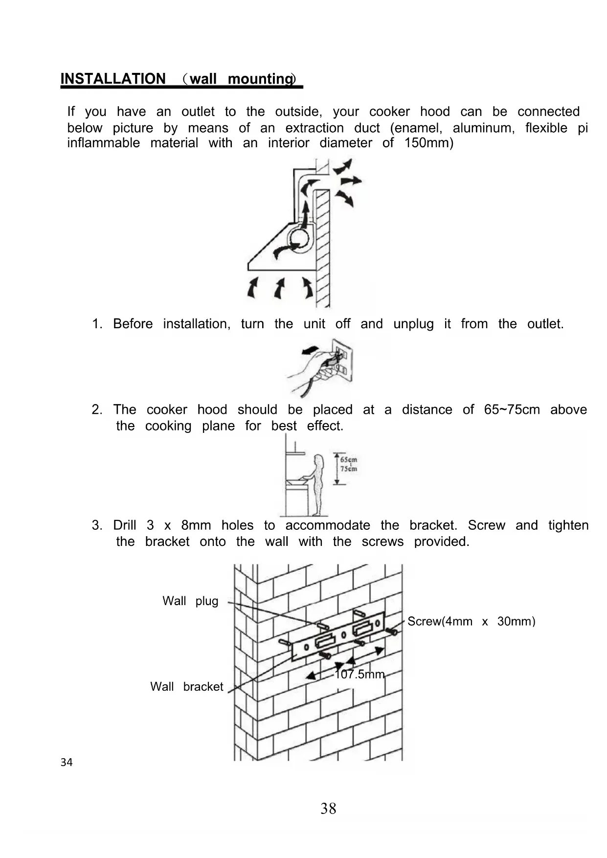
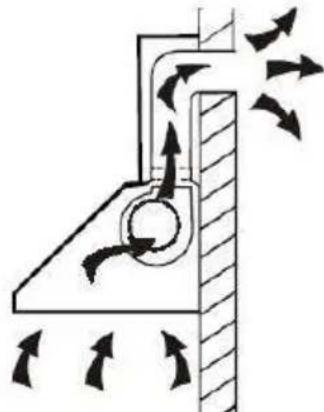
If you have an outlet to the outside, your cooker hood can be connected below picture by means of an extraction duct (enamel, aluminum, flexible non-flammable material with an interior diameter of 150mm)
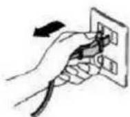
- Before installation, turn the unit off and unplug it from the outlet.
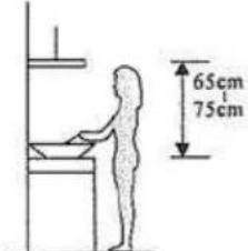
- The cooker hood should be placed at a distance of 65~75 cm above the cooking plane for best effect.
- Drill 3 x 8mm holes to accommodate the bracket. Screw and tighten the bracket onto the wall with the screws provided.
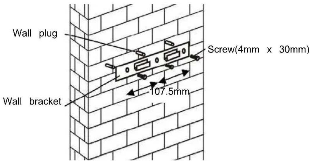
For inclined panel Model
- Need to drill 2x8mm extra holes & fixing screws & screw plugs before installation. For inclined models
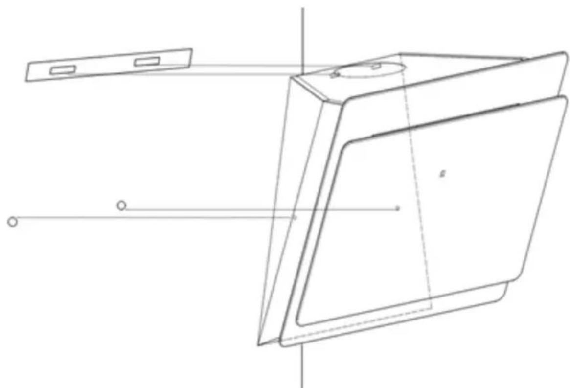
- Leave up the cooker hood and hang onto the wall bracket hook.
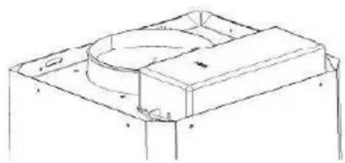
- Fix the one-way-valve to the air outlet of the cooker hood. Then, attached the exhaust pipe onto the one-way-valve as shown below.
Exhaust pipe Cooker hood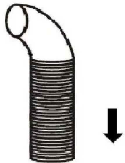
6.
i. Place the glass in appropriate position on the top of the cooker hood.
ii. Fix with 4 screws and washers. In order to avoid the glass cracking, please do not tighten the screws too strongly.
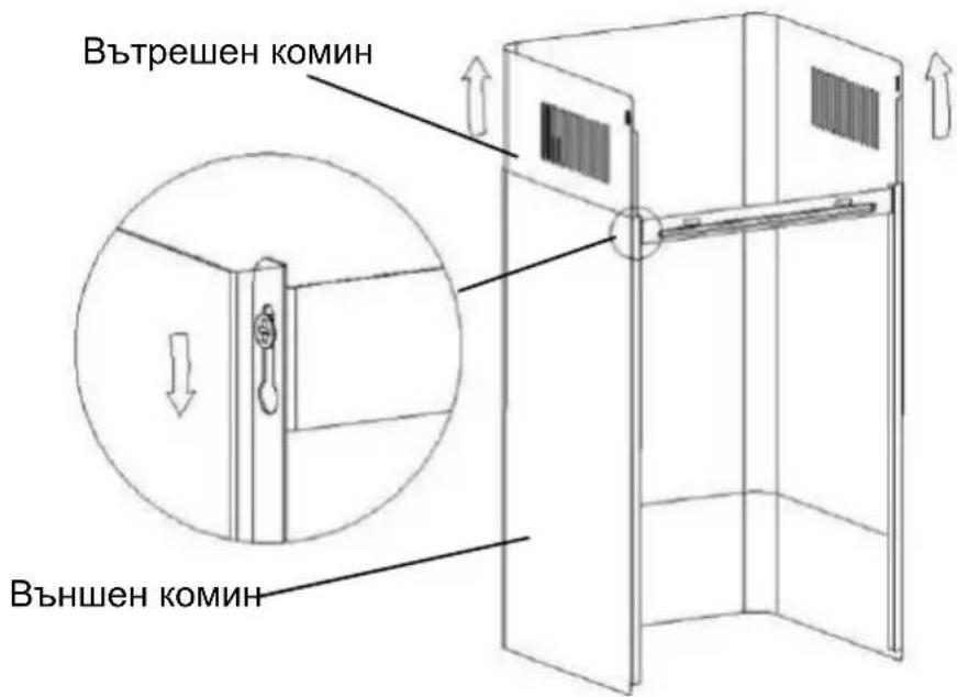
i. Put the inner chimney into the outer chimney. Then pull the inner chimney upwards. Adjust to reach the required height.
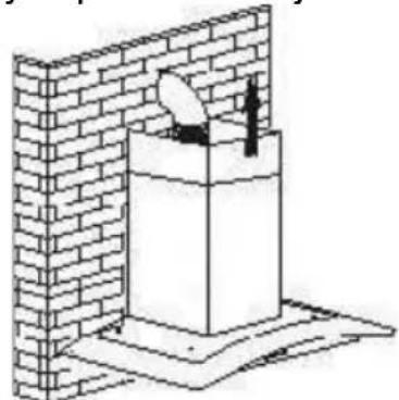
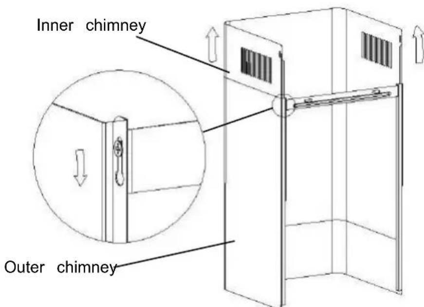
ii. Slide the chimney to adjust the chimney height. When the required height is reached, hang the fixing hole onto the screws as shown in the pictures below.
8.
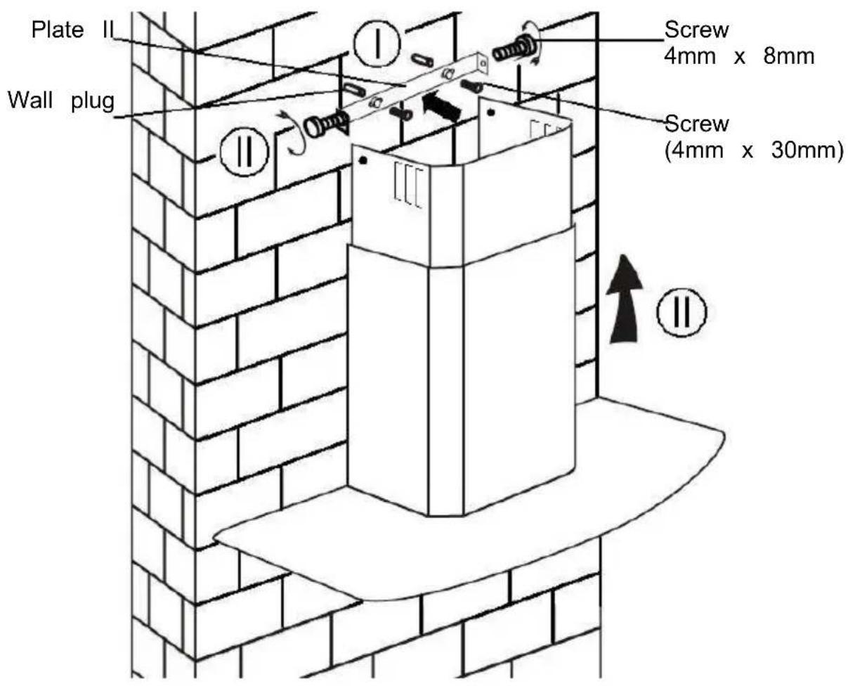
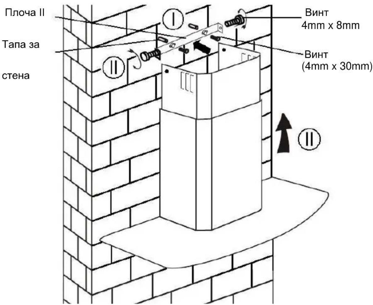
i. Drill 2 x 8mm holes to accommodate the plate II. Screw and tighten the plate II onto the wall with the 2 screws provided. ii. Assemble the chimney onto the unit and fix it with 2 screws.
INSTALLATION (VENT INSIDE)
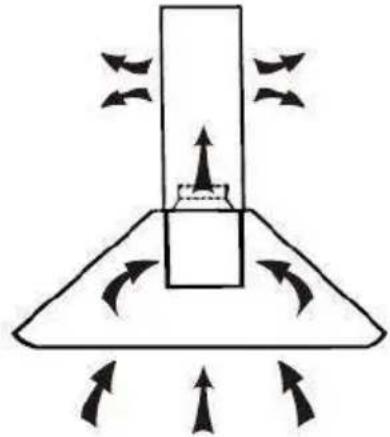
If you do not have an outlet to the outside, the exhaust pipe is not required. The installation is similar to the one shown in section "INSTALLATION (VENT OUTSIDE)".
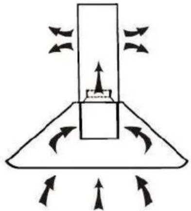
Activated carbon filter can be used to trap odors.
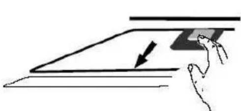
In order to install the activated carbon filter, the grease filter should be detached first. Press the lock and pull it downward.
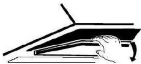
Plug the activated carbon filter into the unit and turn it in a clockwise direction. Repeat the same on the other side.
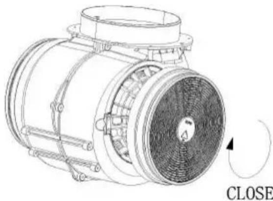
NOTE:
o Make sure the filter is securely locked. Otherwise, it would loosen and cause danger. o When the activated carbon filter is attached, the suction power will be lower.
CONFIGURATION 1


OPERATION
Button 1

The button has an indicator backlight. When you press the button, the backlight will turn on and the fan will turn on at low speed. Pressing it again will turn off the fan.
It is used for ventilation in the kitchen. It is suitable for simmering and cooking that do not produce much steam.
Button 2

The button has an indicator backlight. When you press the button, the backlight will turn on and the fan will turn on at medium speed. Pressing it again will turn off the fan.
Airflow speed is ideal for ventilation during standard cooking operations.
Button 3

The button has an indicator backlight. When you press the button, the backlight will turn on and the fan will turn on at high speed. Pressing it again will turn off the fan.
When high density of smoke or steam is produced, press the high-speed button for the most effective ventilation.
NOTE: If the low, medium, or high speed buttons are pressed at the same time, the unit will only operate at the highest speed.
Light button

CONFIGURATION 2





OPERATION
Off button 0
It's used for turning off the fan.
Low Speed button

It's used for ventilation in the kitchen. It is suitable for simmering and cooking which do not produce much steam.
Medium Speed button

2
Airflow speed is ideally for ventilation in standard cooking operations.
High Speed button

3
When high density of smoke or steam is produced, press the high-speed button for the most effective ventilation.
NOTE: If Low / Medium / High speed buttons are pressed at the same time, the unit will only operate at the highest speed.
Light button

CONFIGURATION 3





1 On/Off button
It's used for turning on/off the fan.
⊕ Speed plus button
For increasing the speed of the fan.
⊙ Speed decrease button
For decreasing the speed of the fan.
Light button
8 Digital display
Fan speed display: "1" for Low speed, "2" for Medium speed, "3" for High speed, "4" for Booster function.
Quick timer: Press & hold for 1 second, Digital display will flash & enter 5 minutes count down, after 5 minutes motor & will turn off automatically & Buzzer sound for 1 second.
Booster function
This hood has a booster function. To activate the booster, press ④ to speed 4, enter into highest speed while the hood is in use and it will increase speed for 5 minutes, before slowing down again.
MAINTENANCE
Before cleaning switch the unit off and pull out the plug.
I. Regular Cleaning
Use a soft cloth moistened with hand-warm mildly soapy water or household cleaning detergent. Never use metal pads, chemical, abrasive material or stiff brush to clean the unit.
II. Monthly Cleaning for Grease Filter
ESSENTIAL: Clean the filter every month to prevent any risk of fire.
The filter collects grease, smoke, and dust, so it directly affects the efficiency of the cooker hood. If not cleaned, grease residue (potentially flammable) will saturate the filter. Clean it with household cleaning detergent.
III. Annual Cleaning for Activated Carbon Filter
Apply SOLELY to units installed as recirculation units (not vented to the outside). This filter traps odors and must be replaced at least once a year
depending on how frequently the cooker hood is used.
IV. Changing a Light Bulb
Remove the screws on the glass, take off the hood glass. Find the bulb that requires replacement; you will find it located in the light fixture inside the exposed section of the canopy.
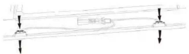
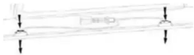
Disconnect the light wiring point and remove the bulb holders and wiring from the hood. Important: It is not possible to replace the bulbs individually; it will be necessary to obtain the bulbs, bulb holders, and wiring as a complete part. (LED light: MAX 1.5W)
Fit the replacement bulbs, bulb holders, and wiring in the same manner as the originals. Then reconnect the light wiring point.
Refit the hood glass and fasten the glass screws. Make sure the screws are fully tightened.
TROUBLESHOOTING
| Fault | Cause | Solution |
| Light on, but fan does not work | The fan blade is jammed. | Switch off the unit and repair qualified service personnel only. |
| The motor is damaged | ||
| Both light and fan do not work | Halogen light bulb bur | Replace the bulb with correct rating. |
| Power cord looses. | Plug in to the power supply ag | |
| Serious Vibration of the unit | The fan blade is damaged. | Switch of the unit and repair b qualified service personnel only. |
| The fan motor is not fixed tightly. | Switch off the unit and repair i qualified service personnel only. | |
| The unit is not hung properly on the bracke | Take down the unit and check whether the bracket is in proper location. | |
| Suction performance not good | Too long distance between the unit and the cooking plane | Readjust the distance to 65-75c |
CUSTOMER ASSISTANCE SERVICE
If you cannot identify the cause of the operating anomaly, switch off the appliance and contact the Assistance Service.
PRODUCT SERIAL NUMBER. Where can I find it?
It is important to inform the Assistance Service of your product code and its serial number (a 16-character code that begins with a number). This can be found on the guarantee certificate or on the data plate located on the appliance.
It will help to avoid wasted journeys to technicians, thereby (and most significantly) saving the corresponding callout charges.
ENVIRONMENTAL PROTECTION
Waste electrical products should not be disposed of with household waste. Please recycle where facilities exist. Check with your Local Authority or retailer for recycling advice.
This appliance is marked according to the European directive 2012/19/EU on Waste Electrical and Electronic Equipment (WEEE).
By ensuring this product is disposed of correctly, you will help prevent potential negative consequences for the environment and human health, which could otherwise be caused by inappropriate waste handling of this product.
The symbol on the product indicates that this product may not be treated as household waste. Instead it shall be handed over to the applicable collection point for the recycling of electrical and electronic equipment. Disposal must be carried out in accordance with local environmental regulations for waste disposal.
For more detailed information about treatment, recovery and recycling of this product, please contact your local city office, your household waste disposal service or the shop where you purchased the product.
INSTALLATION AND USE NOTICE
Table of contents
The appliance must be connected directly to the mains using an omnipolar circuit breaker with a minimum opening of 3 mm between the contacts.
The cable must not be bent or compressed.
For decreasing the speed of the fan.
O
Light button
8
Digital display
Fan speed display: "1" for Low speed, "2" for Medium speed, "3" for High speed, "4" for Booster function.
Quick timer: Press and hold for 1 second. The digital display will flash and enter a 5-minute countdown. After 5 minutes, the motor and light will turn off automatically, and a buzzer will sound for 1 second.
Booster function
Blue = N or Neutral
Installation (wall mounting)
(Waste Electrical and Electronic Equipment - WEEE).

INSTALLATION (EXTERNAL VENTILATION) 209
INSTALLATION (INTERNAL VENTILATION) 214
DESCRIPTION OF COMPONENTS 215
OPERATION 215
MAINTENANCE 218
TROUBLESHOOTING 219
COMPLIANCE WITH DIRECTIVES 219
ENVIRONMENTAL PROTECTION 220
INTRODUCTION
Blue = N or Neutral
This hood has a booster function. To activate the booster, press to speed 4, enter into highest speed while the hood is in use and it will increase speed for 5 minutes, before slowing down again.
MAINTENANCE
∴ ED = 20













J 1

abwgs 2
aaii iie 1 aie

3
aiee aee eae ee e e e e e e e e e e e e
Lae ie Jw 1e Jd jn







1
1
4.4.1.4
a 2021 a c 2021
中
a 2015
8
a ydy 3y dya y2y aiaia y 4y y 4y
j 2
1 5
g 1
jiaai 1
yI aJyI bI yI bI aI JyI bI yI .jyaiy I yI oii yI oii jy
.
i
1
alba jia jiall jie L 1jia o jia o jia o jia o jia o jia o jia o jia o jia o jia o jia o
p 11.
.
i 1
buiy jy yj y y
120 120
sclai Cuaa .IV
i 1
| الله | الإستعمال | الإستعمال |
| ملاوي | %.شامعية الحرفية محيى | %.شامعية الحرفية محيى |
| %.الإستعمال TLS | %.ال,enGLISH TLS | |
| %.ال,enGLISH TLS | %.ال,enGLISH TLS | %.ال,enGLISH TLS |
| %.ال,enGLISH TLS | %.ال,enGLISH TLS | %.ال,enGLISH TLS |
| %.ال,enGLISH TLS | %.ال,enGLISH TLS | %.ال,enGLISH TLS |
| %.ال,enGLISH TLS | %.ال,enGLISH TLS | %.ال,enGLISH TLS |
| %.ال,enGLISH TLS | %.ال,enGLISH TLS | %.ال,enGLISH TLS |
| %.ال,enGLISH TLS | %.ال,enLANGUAGE | %.ال,enLANGUAGE |
| %.ال,enLANGUAGE | %.ال,enLANGUAGE | %.ال,enLANGUAGE |
| %.ال,enLANGUAGE | %.ال,enLANGUAGE | %.ال,enLANGUAGE |
| %.ال,enLANGUAGE | %.ال,enLANGUAGE | %.ال,enLANGUAGE |
| %.ال,enLANGUAGE | %.ال,enLANGUAGE | %.ال,enLANGUAGE |
| %.ال,enLANGUAGE | %.ال,enLANGUAGE | %.ال,enLANGUAGE |
| %.ال,enLANGUAGE | %.ال,enLANGUAGE | %.ال,enLANGUAGE |
| %.ENGLISH | %.ENGLISH | %.ENGLISH |
| %.ENGLISH | %.ENGLISH | %.ENGLISH |
| %.ENGLISH | %.ENGLISH | %.ENGLISH |
| %.ENGLISH | %.ENGLISH | %.ENGLISH |
| %.ENGLISH | %.ENGLISH | %.ENGLISH |
| %.ENGLISH | %.ENGLISH | %.ENGLISH |
| %.ENGLISH | %.ENGLISH | %.ENGLISH |
| %.ENGLISH | %.ENGLISH | %.ENGLISH |
E U/19/2012 1 1 WEEE
INSTALLATION GUIDE
CONTENTS
INTRODUCTION
SAFETY MEASURES 239
CONTENTS 242
INSTALLATION (EXTERNAL VENTILATION) 243
INSTALLATION (INTERNAL VENTILATION) 248
DESCRIPTION OF COMPONENTS 249
OPERATION 249
MAINTENANCE 252
TROUBLESHOOTING 254
COMPLIANCE WITH DIRECTIVES 254
ENVIRONMENTAL PROTECTION 255
DISPOSAL
ii. Mount with 4 screws. To prevent glass breakage, do not overtighten the screws.
i. Place the inner unit into the outer unit. Then adjust the inner unit upward. Adjust to achieve the desired position.
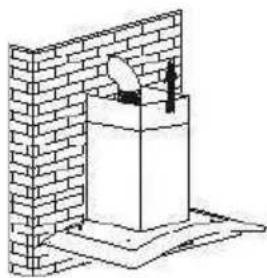
ii. Place the unit on the floor, adjust its height. After reaching the desired height, position the mounting holes towards the screws, as shown in the pictures.
8.
i. Insert the 2 screws and nuts through the 8 mm holes to mount plate II. With the screws, tighten plate II to the wall, leaving the necessary clearance. ii. Insert the chimney into the hole and fix it with 2 screws.
INSTALLATION (INTERNAL VENTILATION)
If you do not have an external vent, the exhaust pipe is not necessary. The installation is similar to that described in the section (INSTALLATION (EXTERNAL VENTILATION)).



- ZANAGNUTIPANEL MODEL
- INSTALLATION AND USER'S MANUAL
- CONTENT
- THANK YOU FOR CHOOSING THIS COOKER HOOD
- SAFETY PRECAUTION
- ELECTRICAL SHOCK HAZARD
- ELECTRICAL INSTALLATION
- DIRECT CONNECTION
- WARNING: THIS IS A CLASS I APPLIANCE AND MUST BE EARTHED
- FOR INCLINED PANEL MODEL
- INSTALLATION (VENT INSIDE)
- NOTE
- CONFIGURATION
- OPERATION
- BUTTON
- LIGHT BUTTON
- OFF BUTTON
- LOW SPEED BUTTON
- MEDIUM SPEED BUTTON
- HIGH SPEED BUTTON
- BOOSTER FUNCTION
- MAINTENANCE
- REGULAR CLEANING
- MONTHLY CLEANING FOR GREASE FILTER
- ANNUAL CLEANING FOR ACTIVATED CARBON FILTER
- CHANGING A LIGHT BULB
- CUSTOMER ASSISTANCE SERVICE
- ENVIRONMENTAL PROTECTION
- INSTALLATION AND USE NOTICE
- TABLE OF CONTENTS
- DIGITAL DISPLAY
- INSTALLATION (WALL MOUNTING)
- INTRODUCTION
- INSTALLATION GUIDE
- CONTENTS
- DISPOSAL
- INSTALLATION (INTERNAL VENTILATION)
Brand : CANDY
Model : CCE60NXS
Category : Range hood