
PowerAir V 400 - Compressor METABO - Free user manual and instructions
Find the device manual for free PowerAir V 400 METABO in PDF.
| Product type | Air compressor |
| Brand | Metabo |
| Model | PowerAir V 400 |
| Dimensions (L x W x H) | 620 x 540 x 775 mm |
| Weight | 47 kg |
| Power supply | 230 V, 50 Hz, 10.8 A |
| Motor power | 2.2 kW |
| Maximum operating pressure | 10 bar |
| Suction flow rate | 340 l/min |
| Effective flow rate | 180 l/min |
| Tank volume | 24 L |
| Number of cylinders | 2 |
| Rotation speed | 1450 min⁻¹ |
| Protection rating | IP44 |
| Fuse protection | 16 A (time-delay) |
| Noise level (sound pressure) | 87 ± 3 dB(A) at 1 m |
| Guaranteed sound power level | 93 dB(A) |
| Operating temperature | +5 °C to +40 °C |
| Recommended oil type | SAE 40 (or SAE 20) |
| Oil quantity for change | 0.37 L |
| Number of air outlets | 1 |
| Maintenance: condensate drain | Daily |
| Maintenance: air filter replacement | Every 250 hours |
| Maintenance: oil change | Every 500 hours |
Frequently Asked Questions - PowerAir V 400 METABO
User questions about PowerAir V 400 METABO
0 question about this device. Answer the ones you know or ask your own.
Ask a new question about this device
Download the instructions for your Compressor in PDF format for free! Find your manual PowerAir V 400 - METABO and take your electronic device back in hand. On this page are published all the documents necessary for the use of your device. PowerAir V 400 by METABO.
USER MANUAL PowerAir V 400 METABO
We herewith declare in our sole responsibility that this product complies with the following standards in accordance with the regulations of the undermentioned Directives testreport ** issuing test office measured/ guaranteed noise sound power level*
NL
Director Innovation, Research and Development
Dokumentationsbevollmachtigter/ responsible person for documentation/ Chargé de la documentation

Metabowerke GmbH
Metabo-Allee 1
D-72622Nurtingen
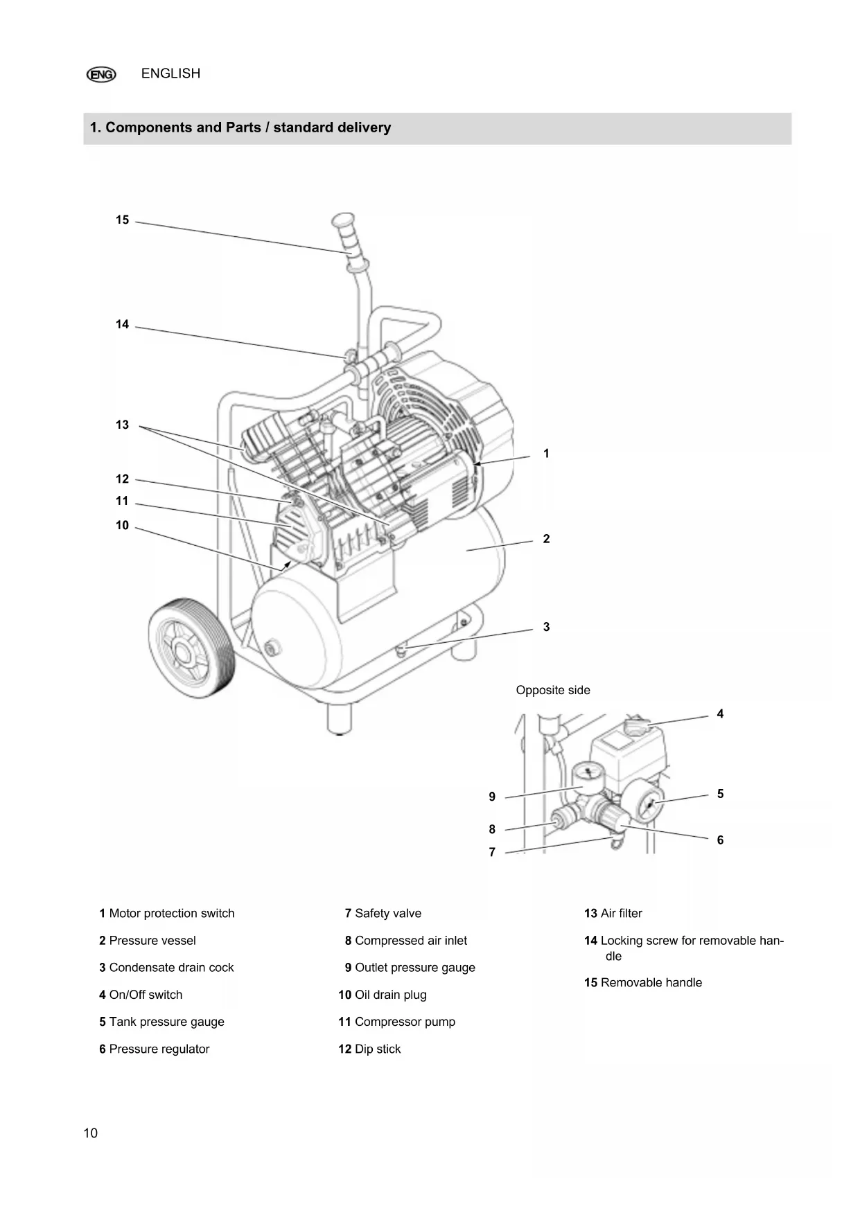
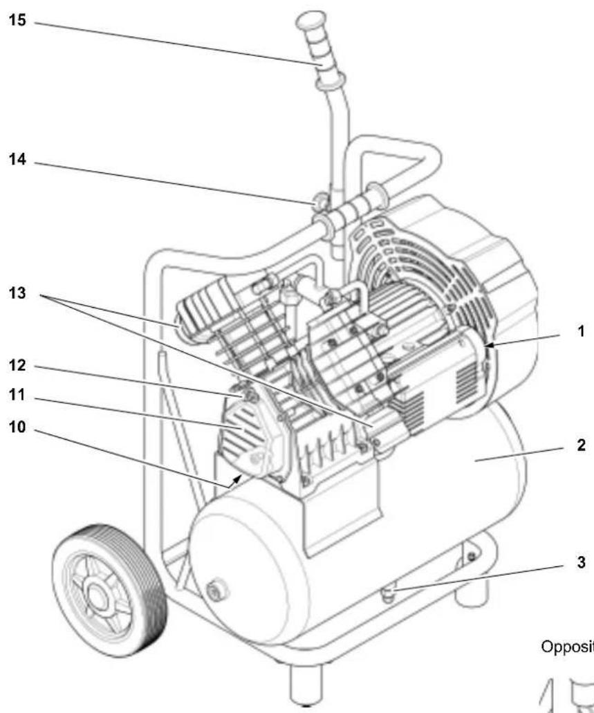
1. Components and Parts / standard delivery
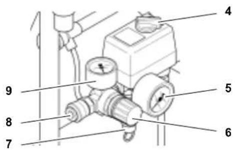
Opposite side
1 Motor protection switch
2 Pressure vessel
3 Condensate drain cock
4 On/Off switch
5 Tank pressure gauge
6 Pressure regulator
7 Safety valve
8 Compressed air inlet
9 Outlet pressure gauge
10 Oil drain plug
11 Compressor pump
12 Dip stick
13 Air filter
14 Locking screw for removable handle
15 Removable handle
Table of Contents
- Components and Parts / standard delivery. 10
- Please Read First! 11
- Safety 11
3.1 Specified conditions of use.....11
3.2 General Safety Instructions ....11
3.3 Symbols on the machine...12
3.4 Safety Devices 13 - Operation 13
4.1 Prior to initial operation. 13
4.2 Mains connection 13
4.3 Generating compressed air ....13 - Care and Maintenance 14
5.1 Important Information 14
5.2 Periodic maintenance. 14
5.3 Saw storage 14 - Trouble Shooting. 14
- Repairs 15
- Environmental Protection....15
- Technical Specifications ....15
2. Please Read First!
These operating instructions have been written so that you can quickly learn how to operate your saw safely. Here is a guide on how you should read these instructions:
- Read these instructions before use. Pay special attention to the safety information.
- These instructions are intended for persons with basic technical knowledge regarding the operation of a device like the one described herein. Inexperienced persons are strongly advised to seek competent advise and guidance from an experienced person before operating this machine.
- Retain all documents delivered together with this device so that you and other users have access to the relevant information at all times. Retain proof of purchase for any future warranty claims.
- If you lend or sell this device be sure to have these Operating Instructions go with it.
- The equipment manufacturer is not liable for any damage resulting from neglect of these operating instructions.
Information in these instructions is designated as under:

Risk of personal injury or environmental damage.
Risk of personal injury by electric shock.

Risk of material damage.

Additional information.
-
Numbers in illustrations (1, 2, 3 etc.)
-
indicate component parts;
- are consecutively numbered;
-
relate to the corresponding number(s) in brackets (1), (2), (3) etc. in the neighbouring text.
-
Numbered steps must be carried out in sequence.
- Instructions which can be carried out in any order are indicated by a bullet point () .
- Listings are marked by a dash (-).
3. Safety
3.1 Specified conditions of use
This machine is intended to generate compressed air required for the operation of air tools. The machine should only be used under supervision.
Any use for medical purposes, food processing as well as filling of oxygen cylinders for breathing equipment is not permitted.
Explosive, combustible gases or gases detrimental to health may not be compressed. Operation in hazardous locations is not permitted.
Any other use is not as specified. Use not as specified, alteration of the ma
chine or use of parts not approved by the equipment manufacturer, can cause unforeseeable damage!
Children, juveniles and persons not having been instructed in its usage are not permitted to operate this machine and any air tools connected to it.
3.2 General Safety Instructions
- When using this electric tool observe the following safety instructions, to exclude the risk of personal injury or material damage.
- Please also observe the special safety instructions in the respective sections.
- Keep all documents, supplied with the machine, for future reference.
- Observe the statuary accident insurance institution regulations and regulations for the prevention of accidents pertaining to the operation of air compressors and air tools, where applicable.
- Observe the legal regulations regarding operation of systems subject to technical inspections.
- When operating and storing the machine be aware that leaking condensate and operating materials can contaminate the environment and lead to environmental damage.
General Hazard!
- Keep your work area tidy - a messy work area invites accidents.
- Be alert. Know what you are doing. Set out to work with reason. Do not operate electric tool while under the influence of drugs, alcohol or medication.
- Consider environmental conditions.
- keep work area well lighted.
- Prevent adverse body positions. Ensure firm footing and keep your balance at all times.
- Do not operate electric tool near in-flammable liquids or gases.
- Keep bystanders, particularly children, out of the work area. Do not permit other persons to touch the tool or power cable while the electric tool is running.
- Do not overload electric tool - use it only within the performance range it
was designed for (see Technical Specifications).

Danger! Risk of electric
shock!
- Do not expose electric tool to rain.
- Do not operate electric tool in damp or wet environment.
- Prevent body contact with earthed objects such as radiators, pipes, cooking stoves or refrigerators when operating this electric tool.
- Do not use the power cable for purposes it is not intended for.

Risk of personal injury by es
caping compressed air and part hurled about by escaping air!
- Never direct compressed air against persons or animals!
- Ensure all air tools and accessories used are designed for the working pressure or are supplied via a pressure regulator.
- Please note that, when disconnecting the quick coupler, the compressed air contained in the pressure hose will escape all of a sudden. You should therefore firmly hold the air hose when disconnecting it.
- Ensure all screwed connections are fully tightened at all times.
- Do not attempt to repair the machine yourself! Only trained specialists are permitted to service or repair compressors, pressure vessels and air tools.

Hazard generated by lubricat
ed compressed air!
- Use lubricated compressed air only for air tools requiring such supply.
- Do not use an air hose used to supply compressed air containing oil to supply air tools not designed for operation on compressed air containing oil.
- Do not fill tyres with lubricated compressed air.

Risk of burns from the surfac
es of parts carrying compressed air!
- Let tool cool off before servicing.

Risk of personal injury and going by moving parts!
- Do not operate the electric tool without installed guards.
- Please note that the compressor will start automatically when the pressure falls off to minimum! - disconnect from power supply prior to any servicing.
- Ensure that when switching on (e.g. after servicing) no tools or loose parts are in the electric tool.

Hazard generated by insuffi- personal protection gear!
- Wear hearing protection.
- Wear safety goggles.
- Wear mask respirator when work generates dust or mist detrimental to health.
- Wear suitable work clothes. When working outdoors wearing of non-slip shoes is recommended.

Hazard generated by electric defects!
- Keep electric tool and accessories in good repair. Observe the maintenance instructions.
- Prior to any use check the electric tool for possible damage: before operating the electric tool all safety devices, protective guards or slightly damaged parts need to be checked for proper function as specified.
- Check to see that all moving parts work properly and do not jam. All parts must be correctly installed and meet all conditions necessary for the proper operation of the electric tool.
- Damaged protection devices or parts must be repaired or replaced by a qualified specialist.
- Have damaged switches replaced by a Service Centre.
- Do not operate electric tool if the switch can not be turned ON or OFF.
- Keep handles free of oil and grease.
3.3 Symbols on the machine
Symbols on the machine


16 17 18 19 20

21
16 Read instructions.
17 Warning that personal injury may occur through touching of hot parts.
18 Wear safety goggles.
19 Warning against automatic startup.
20 Warning against dangerous voltage.
21 Guaranteed sound power level.
Information on nameplate:
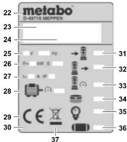
22 Manufacturer
23 Article number, version number, serial number
24 Machine designation
25 Supply voltage / Frequency
26 Motor capacity P 1 (see also "Technical Specifications")
27 Power consumption / Protection rating
28 Motor speed
29 CE-mark - This machine conforms to the EC Directives as per Declaration of Conformity
30 Date of manufacture
31 Suction capacity
32 Filling rate
33 Speed (compressor pump)
34 No. of cylinders
35 Maximum pressure
36 Volume of pressure vessel
37 Waste disposal symbol - Machine can be disposed of by returning it to the manufacturer
3.4 Safety Devices
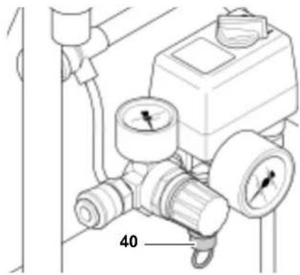
Safety valve
The spring-loaded safety valve (40) can be found on the ON/OFF switch. The safety valve opens if the max. permissible pressure is exceeded.
4. Operation
4.1 Prior to initial operation
Insert dip stick
- Remove the plug (42) from the crankcase.
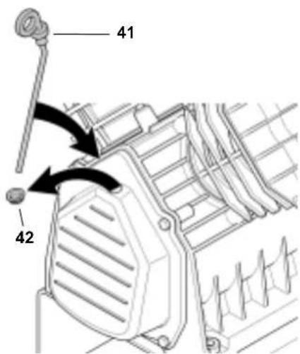
- Substitute the plug (41) with the dip stick supplied.
The plug prevents oil from leaking from the crankcase during shipping. Keep plug for future use.
Assembling the air filter
- Remove the plug from the air inlet of the compressor pump housing. Keep plug for future use.
- Screw the enclosed air filter (44) onto the air inlet (43).
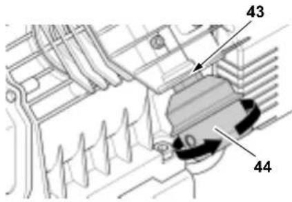
- Proceed in the same way for the second filter.
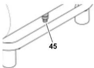
Checking the condensate outlet
Make sure that the outlet screw (45) of the condensate outlet is closed.
4.2 Mains connection

Danger! High voltage
Operate machine in dry environment only. Operate machine only on a power source complying with the following requirements:
outlets properly installed, earthed and tested;
- fuse protection in accordance with the technical specifications.
Make sure that the mains cable is out of the way so that it does not interfere with the work and cannot be damaged.
Always check to see that the machine is switched OFF before plugging in.
Protect mains cable from heat, aggressive liquids and sharp edges.
Use only extension cables with sufficient lead cross section (see "Technical Specifications").
Do not stop the compressor by unplugging, but switch OFF using the switch.
Unplug after use.
4.3 Generating compressed air
- Start compressor (47) and wait until the max. tank pressure is reached (compressor shuts off). The tank pressure is indicated by the tank pressure gauge (48).
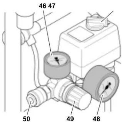
- Set pressure regulator (49) to required working pressure. The current working pressure is indicated by the regulated pressure gauge (46).
Caution!
The regulated pressure may not be set higher than the max. working pressure of the connected air tools!
- Connect air hose to compressed air outlet (50).
- Connect air tool. You are now ready to work with the air tool.
- Switch the compressor OFF (47), if you do not continue working immediately afterwards. Unplug after switching OFF.
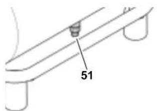
- Drain condensation water from pressure vessel once a day (51).
5. Care and Maintenance

Danger!
Prior to all servicing:
- Switch machine OFF.
- Unplug power cable.
- Wait until the compressor has come to a complete stop.
- Ensure the compressor and all air tools and accessories connected to it are relieved from pressure.
- Let the device and all air tools and accessories cool down.
After all servicing:
- Check to see that all safety devices are operational.
- Make sure that no tools or other parts remain on or in the machine.
Repair and maintenance work other than described in this section must only be carried out by qualified specialists.
5.1 Important Information
Maintenance and inspections must be planned and carried out appropriately for the setup and operating mode of the machine in accordance with legal regulations.
Regulatory authorities may request submission of the corresponding documentation.
5.2 Periodic maintenance
Prior to each use
- Check air hoses for damage, replace if necessary.
- Check all screwed connections for tightness, tighten if necessary.
- Check power supply cable for damage, if necessary have replaced by a qualified electrician.
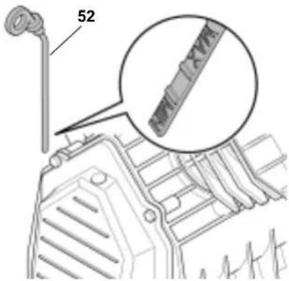
Every 50 hours of operation
- Check air filter element of compressor pump, clean if necessary.
- Check the oil level in the compressor pump with the oil dip stick (52) and refill oil if necessary.
Every 250 operating hours
- Replace air intake filter element of compressor pump.
Every 500 operating hours
- Drain oil and fill with fresh oil.
Every 1000 operating hours
- Have unit serviced by an authorized service station. This will extent the compressor's service life considerably.
5.3 Saw storage
- Switch unit OFF and unplug.
- Release pressure from tank and all connected air tools.
- Drain condensate from pressure vessel.
- Store machine in such way that it cannot be started by unauthorized persons.
Caution!
Do not store or transport machine unprotected outdoors or in damp environment.
Do not lay machine on its side for transportation or storing.
6. Trouble Shooting
Danger!
Prior to all servicing:
- Switch machine OFF.
- Unplug power cable.
-
Wait until the compressor has come to a complete stop.
-
Ensure the compressor and all air tools and accessories connected to it are relieved from pressure.
- Let the device and all air tools and accessories cool down.
After all servicing:
- Check to see that all safety devices are operational.
- Make sure that no tools or other parts remain on or in the machine.
Compressor does not run:
No mains voltage.
-
check cables, plug, outlet and mains fuse.
-
Mains voltage too low.
-
Use only extension cables with sufficient lead cross section (see "Technical Specifications"). When the machine is cold avoid extension cables and relieve the pressure in the pressure vessel.
-
Compressor was stopped by unplugging.
-
Switch compressor OFF at the On/Off switch, then ON again.
-
Motor has overheated, caused by insufficient cooling (cooling fins covered).
-
First switch off the compressor using the ON/OFF switch and allow to cool.
-
Eliminate the cause of overheating.
-
Check the motor protection switch; reset if necessary.
-
Switch the compressor back on.
Compressor runs but does not build up sufficient pressure.
- Condensation water drain on pressure vessel leaky.
- Check the sealing of the outlet screw(s); replace if necessary.
- Tighten the outlet screw(s) hand-tight.
- Check valve leaky.
- Have check valve serviced by qualified service centre.
Air tool is not supplied with sufficient pressure.
- Pressure regulator not opened wide enough.
- Open pressure regulator more.
- Hose connection between compressor and air tool leaky.
- Check air hoses, replace defective parts if necessary.
Further work on the machine should only be carried out by a qualified electrician or the Service Centre in your country.
7. Repairs

Repairs to electric tools must be carried out by qualified electricians only!
Electric tools in need of repair can be send to the service centre in your country. Refer to the spare parts list for the address.
Please attach a description of the fault to the power tool.
8. Environmental Protection

The condensation water from the pressure vessel contains oil residues. Dis- pose of the condensation water in an environmentally-oriented manner at one of the appropriate collection points!

Dispose of the waste oil from the compressor pump in an environmentally-oriented manner at one of the appropriate collection points!
The machine's packaging can be 100% recycled.
Worn out machines and accessories contain considerable amounts of valuable raw and plastic materials, which can be recycled.
These instructions are printed on paper produced with elemental chlorine-free bleaching process.
9. Technical Specifications
| Suction capacity l/min 340 | ||
| Free air delivery (volume flow rate) l/min 180 | ||
| Filling rate l/min 220 | ||
| Max. operating pressure bar 10 | ||
| Max. bearing- / operating temperature *) | °C | + 40 |
| Min. bearing- / operating temperature **) | °C | + 5 |
| Pressure vessel volume | l | 24 |
| No. of air outlets | 1 | |
| No. of cylinders | 2 | |
| Driving torque Cylinder head bolt | Nm | 10 |
| Motor speed | min-1 | 1450 |
| Motor capacity | kW | 2,2 |
| Supply voltage (50 Hz) | V | 230 |
| Nominal current | A 10,8 | |
| Fuse protection min. | A | 16 (time-lag) |
| Degree of protection | IP 44 | |
| Max. overall cable length when using extension cables: - for lead cross section of 3 x 1.5 mm2 - for lead cross section of 3 x 2.5 mm2 | m | 10 |
| m | 16 | |
| Oil grade (compressor pump) SAE 40 (SAE 20) | ||
| Required oil quantity (pump) | 0,37 | ||
| Dimensions: length x width x height | mm | 620 × 540 × 775 |
| Weight kg 47 | ||
| Sound pressure level LPA in 1 m max. dB (A) 87 + 3 | ||
| Guaranteed sound power level LWA | dB (A) 93 | |
| All technical specifications apply to an ambient temperature of 20 °C. | ||
| *) The technical life of some components, the check valve sealing, for instance, is substantially decreased when the compressor is used at high temperatures (max. storage/operating temperature and higher). | ||
| **) At temperatures below the min. storage/operating temperature there persists a danger of the condensate in the pressure vessel freezing. | ||
Todas as 50 horas de operacao
- Verificar ventilador no compressor. Se necessario, limpe-o.
- Verificar;nivel de oleo do compres-sor na vareta de nivel de oleo (52). Se necessario, reabastecer com oleo.

Todas as 250 horas de operacao
Todas as 500 horas de operacao
- Drenar o oleo e abastecer com oleo novo.
Todas as 1000 horas de operacao


- NL
- Components and Parts / standard delivery
- Table of Contents
- Please Read First!
- Safety
- Specified conditions of use
- General Safety Instructions
- General Hazard!
- Danger! Risk of electric
- shock!
- Risk of personal injury by es
- caping compressed air and part hurled about by escaping air!
- Hazard generated by lubricat
- ed compressed air!
- Risk of burns from the surfac
- es of parts carrying compressed air!
- Risk of personal injury and going by moving parts!
- Hazard generated by insuffi- personal protection gear!
- Hazard generated by electric defects!
- Symbols on the machine
- Symbols on the machine
- Information on nameplate:
- Safety Devices
- Operation
- Prior to initial operation
- Insert dip stick
- Assembling the air filter
- Checking the condensate outlet
- Mains connection
- Danger! High voltage
- Generating compressed air
- Caution!
- Care and Maintenance
- Prior to all servicing:
- After all servicing:
- Important Information
- Periodic maintenance
- Prior to each use
- Every 50 hours of operation
- Every 250 operating hours
- Every 500 operating hours
- Every 1000 operating hours
- Saw storage
- Trouble Shooting
- Danger!
- Compressor does not run:
- Compressor runs but does not build up sufficient pressure.
- Air tool is not supplied with sufficient pressure.
- Repairs
- Environmental Protection
- Technical Specifications
- Todas as 50 horas de operacao
- Todas as 250 horas de operacao
- Todas as 500 horas de operacao
- Todas as 1000 horas de operacao
Brand : METABO
Model : PowerAir V 400
Category : Compressor