
DP 185 SA - Pump METABO - Free user manual and instructions
Find the device manual for free DP 185 SA METABO in PDF.
| Product type | Submersible drainage pump |
| Brand | Metabo |
| Model | DP 185 SA |
| Category | Pump |
| Mains voltage | 230 V (standard estimate) |
| Electrical protection | 30 mA residual current device recommended |
| Float switch | Yes, adjustable |
| Permitted liquids | Clear water and wastewater (pH 6-9, max grain size depending on model) |
| Max liquid temperature | 35 °C |
| Dimensions | approx. 60 cm x 60 cm |
| Power cable | With connector |
| Pressure connection | Thread (not specified) |
| Suction openings | Yes |
| Usage | Construction sites, agriculture, domestic, gardens |
| Maintenance | Rinse with clear water, clean deposits with brush and dish soap |
| Storage | Frost-free |
| Safety | Do not use when people are in the water, disconnect before maintenance |
| Repairs | By qualified electrician, Metabo parts |
| Disposal | Recycling according to regulations |
Frequently Asked Questions - DP 185 SA METABO
User questions about DP 185 SA METABO
0 question about this device. Answer the ones you know or ask your own.
Ask a new question about this device
Download the instructions for your Pump in PDF format for free! Find your manual DP 185 SA - METABO and take your electronic device back in hand. On this page are published all the documents necessary for the use of your device. DP 185 SA by METABO.
USER MANUAL DP 185 SA METABO
natural_image
Four metal hydroponic water pumps with visible branding and specifications (no text or symbols on the pump bodies)
DP 18-5 SA DP 28-10 S Inox
3
4
natural_image
Technical line drawing showing three mechanical components with circular annotations highlighting connection points (no text or symbols present)Achtung!
Original instructions
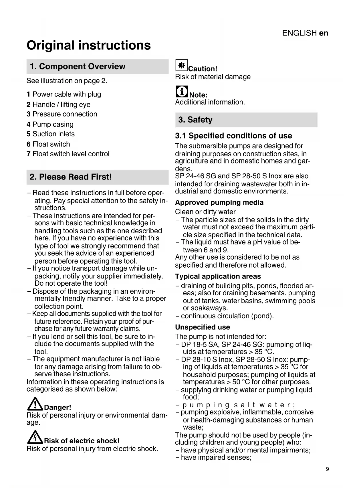
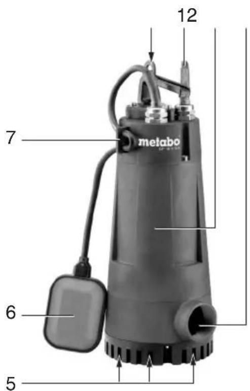
1. Component Overview
See illustration on page 2.
1 Power cable with plug
2 Handle / lifting eye
3 Pressure connection
4 Pump casing
5 Suction inlets
6 Float switch
7 Float switch level control
2. Please Read First!
- Read these instructions in full before operating. Pay special attention to the safety instructions.
- These instructions are intended for persons with basic technical knowledge in handling tools such as the one described here. If you have no experience with this type of tool we strongly recommend that you seek the advice of an experienced person before operating this tool.
- If you notice transport damage while un- packing, notify your supplier immediately. Do not operate the tool!
- Dispose of the packaging in an environmentally friendly manner. Take to a proper collection point.
- Keep all documents supplied with the tool for future reference. Retain your proof of purchase for any future warranty claims.
- If you lend or sell this tool, be sure to include the documents supplied with the tool.
- The equipment manufacturer is not liable for any damage arising from failure to observe these instructions.
Information in these operating instructions is categorised as shown below:

Danger!
Risk of personal injury or environmental damage.

Risk of electric shock!
Risk of personal injury from electric shock.
Caution!
Risk of material damage
Note:
Additional information.
3. Safety
3.1 Specified conditions of use
The submersible pumps are designed for draining purposes on construction sites, in agriculture and in domestic homes and gardens.
SP 24-46 SG and SP 28-50 S Inox are also intended for draining wastewater both in industrial and domestic environments.
Approved pumping media
Clean or dirty water
- The particle sizes of the solids in the dirty water must not exceed the maximum particle size specified in the technical data.
- The liquid must have a pH value of between 6 and 9.
Any other use is considered to be not as specified and therefore not allowed.
Typical application areas
- draining of building pits, ponds, flooded areas; also for draining basements. pumping out of tanks, water basins, swimming pools or soakaways.
– continuous circulation (pond).
Unspecified use
The pump is not intended for:
- DP 18-5 SA, SP 24-46 SG: pumping of liquids at temperatures >35^ .
- DP 28-10 S Inox, SP 28-50 S Inox: pumping of liquids at temperatures >35^ for household purposes; pumping of liquids at temperatures >50^ for other purposes.
– supplying drinking water or pumping liquid food;
-pumping salt water; - pumping explosive, inflammable, corrosive or health-damaging substances or human waste;
The pump should not be used by people (including children and young people) who:
– have physical and/or mental impairments;
– have impaired senses;
ENGLISHen
– do not have adequate experience and/or knowledge in handling the pump; or
– have not read and understood the operating instructions.
Children should be supervised to ensure that they do not play with the device.
The manufacturer assumes no liability for damage caused by unspecified use.
Unspecified use, modification of the pump or use of parts that have not been tested and approved by the manufacturer can cause unforeseeable damage!
3.2 General safety instructions
- When using this pump, observe the following safety instructions to exclude the risk of personal injury or material damage.
– Follow the legal guidelines or accident prevention regulations for using submersible pumps. - When the pump is being used in swimming pools, garden ponds and in the protected areas around them, the regulations must be observed in accordance with IEC 60364-7-702.
All national regulations relating to the safe operation of submersible pumps must also be followed.
- The pump must be protected by a residual current device (RCD) with a trip current of max 30 mA.

General danger!
Do not operate the pump if anyone is in contact with the pumping media (e.g. in a swimming pool or garden pond)!
The following residual risks essentially remain when operating submersible pumps and cannot be fully eliminated – even by employing safety devices.

Danger from the environment!
Do not use the pump in hazardous locations or near inflammable liquids and gases!

Danger! Risk of electric shock!
Do not touch the plug with wet hands! To disconnect, always pull on the plug, not the power cable.
Connect only to an earthed outlet that is properly installed, earthed and tested. Mains voltage and fuse protection must correspond to those stated in the 'Technical Specifications'.
Always lift and transport the pump by the handle, never by the power cable or discharge hose.
Extension cables must have sufficient conductor cross sections. Unroll cable reels fully. Do not buckle, squeeze, drag or drive over power cable or extension cables; protect from sharp edges, oil and heat.
Place extension cable so that it cannot get into the fluid to be pumped.
Always unplug before servicing the pump.

Risk of electric shock from pumps!
Before each use, check the equipment - especially the power and extension cables, power plug and float switch - for possible damage. Risk of fatal electric shock!
Do not attempt to repair the pump yourself!
When repaired inexpertly, there is a risk of liquid entering the electrical parts of the pump.

Caution!
To avoid water damage, e.g. flooded rooms, caused by pump malfunctions or defects: provide for suitable safety measures such as the following:
- a l a r m o r
– collection tank with monitoring.
The manufacturer is not liable for any damage caused by:
- improper use of the pump;
– failure to operate and store the pump in a frost-free environment;
– unauthorised modification of the pump (repairs to electrical equipment may only be carried out by qualified electricians!);
– use of spare parts which have not been tested and approved by the manufacturer; or
– use of unsuitable installation materials (fittings, connection lines etc.).
Suitable installation materials:
– pressure-resistant (min. 10 bar)
- heat-resistant (min. 100°C).
4. Assembly and Installation
4.1 Connecting the discharge line
Connecting thread details: see Technical Specifications.
Note:
The optimum pump capacity is achieved by selecting the largest discharge line diameter.
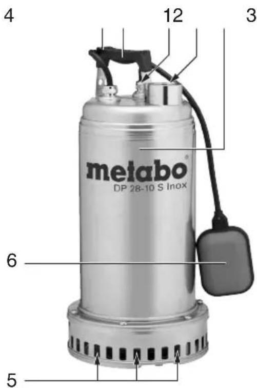
4.2 Fixing the float switch cable
- How the float switch cable is fixed to the device depends on the particular device model. If necessary, insert the float switch cable in the cable clip of the handle.
The following illustration shows the fixed float switch cable.
natural_image
Technical line drawing of electrical components with magnified views of cable connections (no text or symbols)Caution!
The float switch cable may be damaged. Never pull on the float switch cable to change its position in the cable holder!
4.3 Installation instructions
- For the float switch to function properly, it must be able to move freely.
Space requirement for DP 18-5 SA, DP 28-10 S Inox: approx. 60 cm x 60 cm Space requirement for SP 24-46 SG, SP 28-50 S Inox: approx. 70 cm x 70 cm. - Submerge the pump to no more than the maximum immersion depth specified in the technical data.
- Install the pump such that the suction inlets cannot be blocked by foreign objects. If necessary place the pump on a support surface.
- Ensure sufficient upright stability.

Risk of electric shock from severed es!
Do not lift or transport the pump by the cables or the discharge hose! The cables and the discharge hose are not designed to withstand the tensile stress produced by the weight of the pump.
4.4 Installing the pump
- Submerge pump at a slight angle to avoid creating an air cushion on the underside, which would prevent priming. Once the
pump is submerged, it can be placed upright.
- Lower pump to the bottom of the fluid container.
Use a strong rope fastened to the lifting eye to lower the pump.
The pump can also be operated when suspended by a rope.
- Before operating the pump again, ensure that the pump line has been completely emptied.
5. Operation
5.1 Switching ON and OFF
After you have connected the pump to the mains, it will be switched on (9) and off (10) automatically by the float switch. The point in time at which switching occurs depends on the water level.
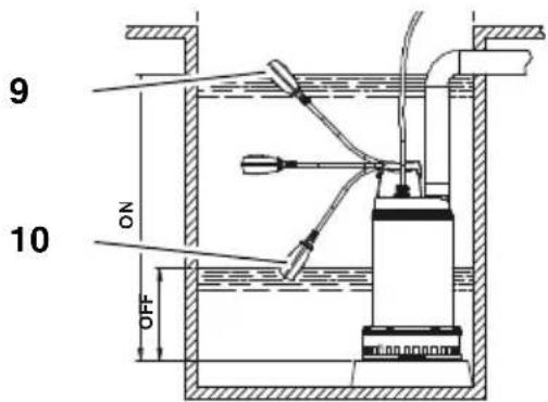
Adjusting the ON and OFF times for the pump
The position of the float switch cable in the cable holder can be changed. The time interval between pump switch-on and switch-off is thereby adjusted:
- 'Short' float switch cable: ON and OFF positions are close together.
- 'Long' float switch cable: ON and OFF positions are far apart.
Caution!
Attach the float cable so that the OFF position is at least 150 mm above the base of the pump. The pump may run dry and thereby be damaged.
Caution!
The float switch must always be able to move up and down to allow the pump to be switched on and off.
ENGLISHen

Caution!
The pump must not be activated more than 20 times an hour, as this could cause the motor to overheat.

Danger from faulty pump!
Take appropriate measures to ensure that pump faults do not cause consequential damage through flooding of rooms. This must be ensured, for example, through installation of an alarm system or a reserve pump.

Danger!
Do not let the pump run against a closed pump line.
5.2 Minimum water level
Continuous operation:
The pump must be completely submerged for continuous operation to take place.
Restricted operation:
Only restricted operation is possible if the pump is not fully submerged. Note the following restrictions:

Risk of material damage from dry ning of pump!
The pump can overheat and become damaged as the cooling function of the pumped medium is reduced. The thermal switch will react.
- Suction operation for a short period only (2-3 mins).
- Monitor the pump's operation during suctioning.
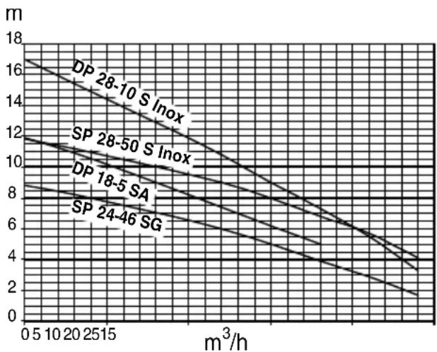
5.3 Pump capacity curve
The pump capacity curve indicates the flow volume, depending on the delivery head.
line
| m³/h | DP 28-10 S Inox | SP 28-50 S Inox | DP 18-5 SA | SP 24-46 SG | |------|-----------------|-----------------|------------|-------------| | 0 | 16 | 12 | 8 | 6 | | 10 | 14 | 10 | 7 | 5 | | 20 | 12 | 8 | 6 | 4 | | 2515 | 10 | 6 | 5 | 3 | | >2515| <10 | <6 | <5 | <4 |6. Device care, maintenance

Danger!
Unplug before maintaining or cleaning.
Repair and maintenance work other than described in this section should only be carried out by qualified specialists.
6.1 Regular care
Regular care is required for the pump to function perfectly at all times. This also applies if the pump is not switched on for extended periods of time (e.g. during operation in soakaways).
Cleaning the pump
- Rinse pump with clean water. Remove persistent marks, e.g. algae deposits, with brush and dishwashing liquid.
- To rinse the inside of the pump: dip pump into a container of clean water and switch on briefly.
6.2 Pump storage

Caution!
Frost damages the pump and accessories as both always contain water!
- If there is a danger of frost, disassemble pump and accessories and store in frost-free conditions.
6.3 Device maintenance (only for SP 28-50 S Inox, DP 28-10 S Inox)

Caution!
Lubricant may leak from the pump if the seals are defective, causing contamination of the liquid being pumped.
Although the lubricant contained in the submersible pump for dirty water is non-toxic, it can alter the water properties.

Danger!
Maintenance work must only ever be carried out by qualified, specially trained staff. After 4,000 to max. 8,000 hours of operation, and in any case at least once a year, the quantity and quality of the oil in the oil reservoir must be checked.
7. Troubleshooting

Danger!
Prior to all servicing:
Unplug.
7.1 Troubleshooting guide
Pump does not run:
- No mains voltage.
- Check cables, plug, outlet and mains fuse.
- Mains voltage too low.
- Use an extension cable with sufficient conductor diameter.
- Motor overheated; motor protection relay tripped.
- Eliminate the cause of overheating (pump blocked by foreign objects?).
- Float switch does not switch pump ON when water level rises.
- Make sure the float switch can move unrestrictedly. If, despite sufficient mobility of the float switch, the pump does not switch ON: send the pump to the service centre in your country.
Motor hums, but does not start:
- Pump blocked by foreign objects.
– Clean impeller.
Pump runs, but does not pump properly:
• Delivery head too high.
- Observe max delivery head (see 'Technical Specifications').
• Discharge hose kinked.
– Straighten discharge hose.
• Discharge hose leaky.
- Seal discharge hose; tighten screw fittings.
Pump runs very noisily:
- Pump is sucking air.
- Ensure there is a sufficient water supply.
– Foreign objects are present (clean pump). - Manual mode has been set (shallow water suctioning).
- Hold pump at an angle when submerging.
Pump runs continuously:
- Float switch does not reach cut-out position.
- Make sure the float switch can move freely.
8. Repairs

Danger!
To avoid risks, only have repairs carried out by qualified electricians using original Metabo spare parts.
If you have Metabo electrical tools that require repairs, please contact your Metabo service centre. For addresses see www.metabo.com.
9. Disposal
Observe national regulations on environmentally compatible disposal and on the recycling of disused machines, packaging and accessories.
Power tools do not belong in the household rubbish. According to European Directive 2002/96/EC on waste electrical and electronic equipment, electrical waste must be collected separately and taken
to an environmentally friendly recycling ?facility.
10. Declaration of Conformity
We, being solely responsible, hereby declare that these submersible pumps conform to the standards and direc- tives specified on the last page.
natural_image
Technical line drawing showing three mechanical components with magnified views of internal connections (no text or symbols)
Attention!
– alarminrichting of
natural_image
Three technical diagrams showing mechanical components with magnified views of a cable or wire connection (no text or symbols present)Attentie!
5.2 Minimale waterstand
Continubedrijf:
natural_image
Technical line drawing of electrical connectors and wiring (no text or symbols)
¡Atención!
natural_image
Technical line drawing of a mechanical assembly with three views of a component (no text or symbols present)
Atenção!
natural_image
Technical line drawing of three mechanical components with magnified views of internal connections (no text or symbols)
OBS!
natural_image
Technical line drawing of three mechanical components with magnified views of internal connections (no text or symbols)Huomio!
Director Product Engineering & Quality Responsible Person for Documentation Metabowerke GmbH, 72622 Nuertingen, Germany


- Achtung!
- Original instructions
- Component Overview
- Please Read First!
- Danger!
- Risk of electric shock!
- Caution!
- Note:
- Safety
- Specified conditions of use
- Approved pumping media
- Typical application areas
- Unspecified use
- ENGLISHen
- General safety instructions
- General danger!
- Danger from the environment!
- Danger! Risk of electric shock!
- Risk of electric shock from pumps!
- Assembly and Installation
- Connecting the discharge line
- Fixing the float switch cable
- Installation instructions
- Risk of electric shock from severed es!
- Installing the pump
- Operation
- Switching ON and OFF
- Adjusting the ON and OFF times for the pump
- Danger from faulty pump!
- Minimum water level
- Continuous operation:
- Restricted operation:
- Risk of material damage from dry ning of pump!
- Pump capacity curve
- Device care, maintenance
- Regular care
- Cleaning the pump
- Pump storage
- Device maintenance (only for SP 28-50 S Inox, DP 28-10 S Inox)
- Troubleshooting
- Troubleshooting guide
- Pump does not run:
- Motor hums, but does not start:
- Pump runs, but does not pump properly:
- Pump runs very noisily:
- Pump runs continuously:
- Repairs
- Disposal
- Declaration of Conformity
- Attention!
- Attentie!
- Minimale waterstand
- Continubedrijf:
- ¡Atención!
- Atenção!
- OBS!
- Huomio!
Brand : METABO
Model : DP 185 SA
Category : Pump