
GCM 10 SD Professional - Saw BOSCH - Free user manual and instructions
Find the device manual for free GCM 10 SD Professional BOSCH in PDF.

| Product Type | Compound miter saw |
| Brand | Bosch |
| Model | GCM 10 SD Professional |
| Rated power input | 1800 W (depending on variant) |
| Supply voltage | 230 V AC |
| Frequency | 50 Hz |
| No-load speed | 4500 min⁻¹ |
| Saw blade diameter | 254 mm (10 inches) |
| Blade bore | 30 mm or 25.4 mm depending on variant |
| Weight without cord | 16.0 kg |
| Horizontal cutting angle | -48° to +48° (presets at 0°, 15°, 22.5°, 31.6°, 45°) |
| Vertical cutting angle | 0° to 45° (presets at 0°, 33.9°, 45°) |
| Maximum workpiece dimensions (at 0°/0°) | 89 x 95 mm (height x width) |
| Sound pressure level (LpA) | 97 dB(A) |
| Sound power level (LwA) | 110 dB(A) |
| Vibration (triaxial value) | < 2.5 m/s² |
| Protection class | II (double insulation) |
| Safety devices | Pendulum guard, spindle lock, safety On/Off switch |
| Dust extraction system | Integrated dust bag, adapter for external extraction |
| Included accessories | Clamp, hex key, Allen key, table extension, longitudinal stop |
Frequently Asked Questions - GCM 10 SD Professional BOSCH
User questions about GCM 10 SD Professional BOSCH
0 question about this device. Answer the ones you know or ask your own.
Ask a new question about this device
Download the instructions for your Saw in PDF format for free! Find your manual GCM 10 SD Professional - BOSCH and take your electronic device back in hand. On this page are published all the documents necessary for the use of your device. GCM 10 SD Professional by BOSCH.
USER MANUAL GCM 10 SD Professional BOSCH
natural_image
Illustration of a Bosch cutting machine on a workbench, no text or symbols present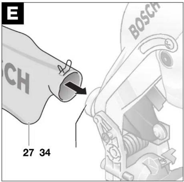
1 GENERAL SAFETY RULES
FOR ELECTRIC TOOLS
WARNING
Read and unders structions. Failure to follow all in- structions listed below may result in electrical shock, fire and/or serious personal injury.
Save these Instructions!
Work Area
Keep your work area clean and well lit. Cluttered benches and dark areas invite accidents.
Do not operate power tools in explosive atmospheres such as in the presence of flammable liquids, gases, or dust. Power tools generate sparks which may ignite the dust or fumes.
Keep bystanders, children, and visitors away while operating a power tool. cause you to lose control.
Do not let the elector-tool continue to run when not attended - switch it off. Do not leave the elec- tro-tool until the tool has come to a complete stand still.
Dress properly i nDo not wear loose clothing or jewelry. Contain long hair. Keep your hair, clothing and gloves away from moving parts. Loose clothes, jewelry or long hair can become caught in moving parts.
Avoid accidental starting. Be sure the switch is off before inserting the plug. Carrying a tool with your finger on the switch or plugging in a tool that is switched on invites an accident.
Remove adjusting keys or wrenches before turning the tool on. A wrench or a key that is left attached to a rotating part of the tool may result in personal injury.
Do not overreach. Keep proper footing and balance at all times. Proper footing and balance enable a better control of the tool in unexpected situations.
Use safety equipment. Always wear eye protection. A dust mask, non-skid safety shoes, hard hat, or hearing protection must be used as appropriate for the conditions.
Electrical Safety
Before connecting the electro-tool, ensure that the voltage of the power source agrees with that give on the nameplate or deviates by a maximum of no more than 10%. If the voltage of the power source is not compatible with the voltage required by the electro-tool, a serious accident and damage to the electro-tool can result.
Avoid body contact with grounded surfaces such as pipes, radiators, ranges and refrigerators.
There is an increased risk of electrical shock if your body is grounded.
Don't expose power tools to rain or wet conditions. Water entering a power tool will increase the risk of electrical shock.
Do not abuse the cord. Never use the cord to carry the tools or pull the plug from an outlet. Keep the cord away from heat, oil, sharp edges or moving parts. Replace damaged cords immediately. Damaged cords increase the risk of electrical shock.
Personal Safety
Stay alert, watch what you are doing and use common sense when operating a power tool. Do not use a tool while tired or under the influence of drugs, alcohol, or medication. A moment of in-attention while operating a power tool may result in serious personal injury.
Power Tool Handling and Usage
Use clamps or other practical means to secure and support the work piece on a stable platform.
Holding the work by hand or against your body is unstable and may lead to loss of control.
Do not force the tool. Use the correct tool for your application. The correct tool will do the job better and safer at the rate for which it is designed.
Do not use a tool if the switch does not turn it on and off. A tool that cannot be controlled with the switch is dangerous and must be repaired.
Disconnect the plug from the power source before making any adjustments, changing accessories or storing the tool. Such preventive safety measures reduce the risk of starting the tool accidentally.
Store tools when not in use out of reach of children and other inexperienced persons. Tools are dangerous in the hands of inexperienced users.
Maintain tools with care. Keep cutting tools sharp and clean. Properly maintained tools with sharp cutting edges are less likely to bind and are easier to control.
Check for misalignment or binding of moving parts, breakage of parts and any other condition that may affect the tool's operation. If damaged, have the tool serviced before using. Many accidents are caused by poorly maintained tools.
Do not make changes to the electro-tool or use it for purposes other that those described in the "Intended Use" Section. Any modification is a misuse and can lead to serious injuries.
Use only accessories that are recommended by the manufacturer for your model. Accessories that may be suitable for one tool, may become hazardous when used on another tool.
Service
Tool repair must be performed only by qualified repair personnel. Repairs or maintenance performed by unqualified personnel could result in a risk of injury.
When repairing a tool, use only identical replacement parts. Follow instructions in the maintenance section of this manual. The use of unauthorized parts or failure to follow maintenance instructions may create a risk of shock or injury.
2 SPECIFIC SAFETY RULES
FOR COMPOUND MITER SAWS
Provide for adequate room lighting at your workplace or for adequate lighting of the immediate work area.
If the power cable is damaged or cut through working, do not touch the cable but pull the power plug immediately. Never use the machine with a damaged cable.
Wear protective glasses and hearing protection.
Dust is generated while working that can be detrimental to health, inflammable or explosive. Suitable protective measure are required.
For example: Some types of dust are considered to be carcinogenic. Use suitable dust vacuuming and wear a dust protection mask.
Connect machines that are used outdoors by means of a fault current circuit breaker (FI) with a maxim triggering current of 30 mA. Use only an extension cable that is approved for outdoor use.
Always lead the cable to the rear away from the machine.
Before using, mount the electro-tool on a flat and stable work surface, e.g., workbench.
Never stand on the electro-tool. Serious injuries could occur when the electro-tool tips over or when coming in contact with the saw blade.
Saw only materials for which the electro proved by the manufacturer.
Ensure that during operation, the swinging guard functions properly. It must move freely and be able to close by itself. It should never be jammed in the open position.
Put the electro-tool in operation only when the working surface is free of all adjustment tools, wood chips, etc. and only the piece to be worked is preserved in pieces of wood or other objects that come in contact with the rotating saw blade can strike the operator with a high speed.
Always firmly clamp the piece to be worked. The free ends of long work pieces must be supported. Do not work with pieces that are to small to clamp. While
Never allow another person to hold or support the work piece while working. Always use a suitable saw table extension or a work piece attachment.
Do not work with material containing asbestos.
Take hold of the electric tool only by the insulated handle when the cutting tool used could come in contact with hidden wiring or its own power cable. Contact with voltage carrying wiring can place the metal parts of the machine also under voltage and lead to an electrical shock.
The saw blade must have reached its full rotational speed before advancing to the work piece.
Keep fingers, hands and arms away from the rotating saw blade.
Do not reach behind the fence in the area of the saw blade to hold the work piece, to remove chips or for any other reason. The distance from your hand to the rotating saw blade is in this case too small.
Always saw only a single work piece. Work pieces place one on the other or next to each other cannot be properly clamped and can cause saw blade blockage or slip with respect to each other during sawing. -tool is ap-
The cutting path must be free from obstacles above and below. Do not saw wood containing nails, screws, etc.
If the saw blade becomes blocked, switch off the electro-tool immediately and pull the power plug. Only then remove the wedged work piece.
Do not ram the saw blade with force into the w piece Smadply too much pressure when using the electro-tool. Especially avoid catching the saw blade when working on corners, edges, etc.
Be careful when slotting that the saw blade does not become jammed in the workpiece.
Avoid overloading the motor especially when working with large work pieces. Apply only light pressure to the handle when sawing.
Caution! The saw blade continues to run after the electro-tool is switched off.
Protect the saw blade from strikes and shocks. Do not apply side pressure to the saw blade.
Use only sharp, flawless crack, bent or dull saw blades without delay.
Select a saw blade suitable for the material to be worked.
Use only saw blades recommended by the manufacturer of the electro-tool.
Observe the instructions of the manufacturer for the mounting and usage of the saw blade.
Actuate the spindle lock only when the saw blade is at a standstill.
The saw blade becomes very hot while working; do not take hold of it until it has cooled.
Wear protective gloves to avoid injury from the sharp cutting edges of the saw blade during changing the saw blade.
Observe the dimensions of the saw blade. The hole diameter must fit the tool spindle without play. Do not use reducer pieces or adapters.
Observe the maximum allowable speed of the saw blade.
w blades. Change
Saw blades of highly alloyed high speed steel (HSS steel) are not to be used.
Never use the electro-tool without the table insert. Replace a defective table insert.
Bosch can ensure flawless functioning of the machine only when original accessories intended for the machine are used.
SYMBOLS
Important notice: Some of the following symbols could have meaning for the use of your tool. Please take note of the symbols and their meaning. The correct interpretation of the symbols will help you to use the tool in a better and safer manner.
| Symbol Name Meaning | ||
| V | Volts | Voltage |
| A | Amperes | Current |
| Ah | Ampere-hours | Capacity, quantity of stored electrical energy |
| Hz | Hertz | Frequency (cycles per second) |
| W | Watt | Power |
| Nm | Newton-meter | Unit of energy |
| kg | Kilograms | Mass, weight |
| mm | Millimetre | Length |
| min/s | Minutes/Seconds | Time |
| °C/°F | Degrees Celsius/Degrees Fahrenheit | Temperature |
| dB | Decibel | Unit of relative loudness |
| ∅ | Diameter | Size of drill bits, grinding wheels, etc. |
| min^-1/n_0 | Revolutions per minute/no load speed | Rotational speed at no load |
| .../min | Revolutions or reciprocation per minute | Revolutions, strokes, surface speed, orbits, etc. per minute |
| 0 | Off position | Zero speed, zero torque... |
| Symbol | Name | Meaning |
| SW Wrench width (in mm) | Distance between parallel surfaces | ces on fastener elements on which the tool must fit on (e.g. hex nuts or hex-head screws), fit over (e.g. ring wrench) or fit in (e.g. socket-head screws). |
| ΩΩ | Left rotation/Right rotation Direction of drive rotation | |
| ○/■ Hex socket drive/ | Square drive Type of tool holder | |
| → | Arrow Action in the direction of arrow | |
| ~ | Alternating current Type or a characteristic of current | |
| == | Direct current Type or a characteristic of current | |
| ~ | Alternating or direct current Type | or a characteristic of current |
| ☐ | Class II construction Designates | double insulated constructed tools |
| ⊕ | Protection class I(Grounding terminal) | Machines of the protection class I must be grounded |
| ⚠️ | Warning symbol | Alerts user to warning messages.Read and understand instructions before operation |
 | Warning symbol | Provides information for correct handling, e.g., read the operating instructions. |
Symbols specifically for this Machine
| Symbol | Meaning | |
 | Warning symbol | Danger area! Keep fingers, hands or arms away from these areas. |
 | Warning symbol | Wear protective glasses. |
 | Warning symbol | Wear hearing protection. |
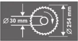 | Note symbol | Observe the dimensions of the saw blade. The hole diameter must fit the tool spindle without play. Do not use reducer pieces or adapters. |
3 FUNCTION

While reading the operating instruc
tions, refer to the corresponding illustrations of the electro-tool on the front pages.
Intended Use
The electro-tool is intended as a stationary machine for making straight lengthways and crossways cuts in wood. Horizontal miter angles of -48^ to +48^ as well as vertical bevel angles of 0^ to +45^ are possible.
Noise/Vibration Information
Measured values are determined according to standard EN 61 029 procedures.
The A-weighted noise levels of the tool are typically:
Sound pressure level: 97 dB(A)
Sound power level: 110 dB(A)
Measurement uncertainty K = 3 dB
Wear ear protection!
The hand-arm vibration is typically below 2.5 m/s ^2 .
Product Specifications
| Compound Mitre Saw GCM 10 | PROFESSIONAL | ||||||
| Order number | ... 003 | ... 004 | ... 005 | ... 006 | ... 014 | ... 034 | |
| 0 601 B20 ... | ... 008 | ||||||
| ... 032 | |||||||
| ... 042 | |||||||
| Rated input power | [W] | 1800 | 1800 | 1650 | 1800 | 1650 | 1650 |
| Voltage | [V] | 230 | 220/230 | 115 | 230/240 | 220 | 120 |
| Frequency | [Hz] | 50 | 50/60 | 50/60 | 50/60 | 50/60 | 60 |
| No load speed | [min-1] | 4500 | 4500 | 4500 | 4500 | 4900 | 4500 |
| Tool spindle | [mm] | 30 | 25.4 | 25.4 | 25.4 | 30 | 16 |
| Weight without mains cable | [kg] | 16.0 | 16.0 | 16.0 | 16.0 | 16.0 | 16.0 |
| Saw blade ∅ | [Inch] | 10 | 10 | 10 | 10 | 10 | 10 |
| Protection class | ☐/II | ☐/II | ☐/II | ☐/II | ☐/II | ☐/II | |
| Compound Mitre Saw GCM 10 | PROFESSIONAL | |||||
| Order number0 601 B20 ... | ... 037 | ... 040 | ... 041 | ... 043 | ... 050 | |
| Rated input power | [W] | 1800 | 1800 | 1650 | 1800 | 1800 |
| Voltage | [V] | 240 | 220 | 110 | 220/230 | 220/230 |
| Frequency | [Hz] | 50 | 60 | 50 | 50 | 50/60 |
| No load speed | [min-1] | 4500 | 4500 | 4500 | 4500 | 4500 |
| Tool spindle | [mm] | 25.4 | 25.4 | 30 | 25.4 | 25.4 |
| Weight without mains cable | [kg] | 16.0 | 16.0 | 16.0 | 16.0 | 16.0 |
| Saw blade ∅ | [Inch] | 10 | 10 | 10 | 10 | 10 |
| Protection class | ☐/II | ☐/II | ☐/II | ☐/II | ☐/II | |
Values apply for the rated voltage [U] of 230/240 V. For lower voltages and models for specific countries, these values can vary.
Switch-on actions cause brief drops in the mains voltage. For unfavourable mains conditions, interference with other equipment can occur.
For mains impedance of less than 0.15 Ω, no interference can be expected.
For maximum work piece dimensions, see the Working Instructions Section
Product Elements
The numbering of the machine elements refers to the illustrations of the electro-tool on the front pages of the operating instructions.
1 Handle
2 On/Off switch
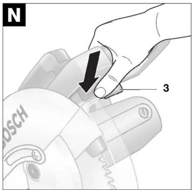
3 Locking lever *
4 Swinging guard
5 Saw blade
6 Fence
7 Quick action clamp
8 Table insert
9 Scale for miter angle (horizontal)
10 Fine scale
11 Locking clamp
12 Locking knob for variable miter angles (horizontal)
13 Lever for miter angle adjustment (horizontal)
14 Detents for standard miter angles
15 Saw table
16 Mounting holes
17 Holes for quick action clamp
18 Socket-head screws (6 mm) of the saw table extension
19 Holes for extension hoop
20 Saw table extension
21 Allen key (6 mm) / Phillips screwdriver
22 Fence extension
23 Stop bolt for 33,9° bevel angle (vertical)
24 Pin of the setting knob for 33.9° bevel angle (vertical)
25 Roller
26 Transport locking pin
27 Dust bag
28 Protective hood
29 Transport handle
30 Clamping lever for fence extension
31 Setting knob for 33.9° bevel angle (vertical)
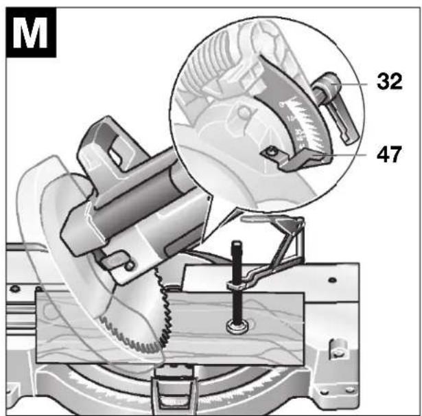
32 Clamping handle for variable bevel angle (vertical)
33 Elongated hole
34 Sawdust ejector
35 Socket-head screws (6 mm) of the fence
36 Ring/open-ended wrench (ring: 13 mm; open-ended: 12 mm)
37 Phillips screw (attachment of the swinging guard)
38 Spindle lock
39 Hex-head bolt for attaching the saw blade
40 Clamping flange
41 Tool spindle
42 Length stop
43 Extension hoop
44 Clamping lever of the quick action clamp
45 Threaded rod of the quick action clamp
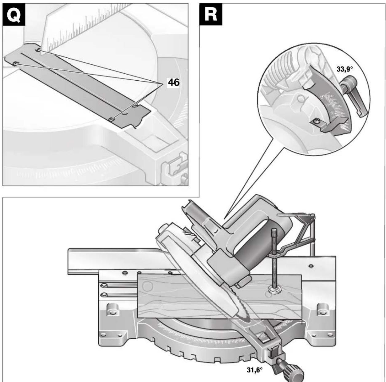
46 Screws of the table insert
47 Angle indicator (vertical)
Not all the accessories illustrated or described are included in standard delivery.
* Not included for the tool executions:
0 601 B20 004, ... 005, ... 006, ... 034, ... 037, ... 040, ... 043, ... 050.
The swinging guard 4 cannot be locked. Perform the operations described in the following accordingly without the locking lever 3.
4 OPERATING INSTRUCTIONS
Transport Safety
(see Figure A)
Before all work on the machine, pull the power plug.
The transport locking pin 26 makes possible easy handling of the machine when transporting to the various working locations.
Securing the Machine (Transport Position)
Press the locking lever 3 (also see the illustration N and, at the same time, swing the tool arm down with the handle 1 to the stop.
Press in the transport safety 26 and release the handle.
Releasing the Machine (Working Position)
Press the tool arm with the handle 1 downward somewhat to relieve the load on the transport locking pin.
Pull the transport safety 26 completely outward.
Guide the tool arm slowly upward.
Mounting the Locking Knob
(see Figure B)
Screw the locking knob 12 into the hole above the lever 13.
Do not tighten the knob too firmly.
Changing the Tool
Before all work on the machine, pull the power plug.
Use only sharp, flawless a cracked, bent or dull saw blades without delay.
Use only saw blades that comply with the characteristic data given in these operating instructions and have been tested according to EN 847-1 and appropriately marked.
Use only saw blades whose allowable rotational speed is as least as high as the no-load speed of the electro-tool.
Actuate the spindle lock only when the saw blade is at a standstill.
The saw blade becomes very hot while working; do not take hold of it until it has cooled.
Wear protective gloves to avoid injury from the sharp cutting edges of the saw blade during changing the saw blade.
Removing the Saw Blade
Place the machine in the working position.
Press the locking lever 3 (also see Figure N) and swing the swinging guard 4 to the rear to the stop. Hold the swinging guard in this position.
Loosen the screw 37 with a commercially available Phillips screwdriver (Caution: Spring loaded!). Do not unscrew the screw completely. (see Figure C1).
Pull the swinging guard completely to the rear until it is held with the pin of the locking lever 3.
Turn the hex-head bolt 39 with the ring wrench 36 (SW 13) provided while pressing the spindle lock 38 at the same time until it engages. (see the illustration C2)
Hold the spindle lock depressed and screw out the hex-head bolt 39 in the clockwise direction (left-hand threads!). Take off the clamping flange 40. Remove the saw blade 5. (see Figure C3)
Mounting the Saw Blade
If necessary, clean all parts to be mounted.
Place the new saw blade on the tool spindle 41. (see Figure C3)

Take care during the mounting that the cutting direction of the teeth (direction of the arrow on the saw blade) agrees with the direction of the arrow on the swinging guard!
Place on the clamping flange 40 and insert the hex-head bolt 39. Press the spindle lock 38 until it engages and tighten the hex-head screw 39 in the counter clockwise direction with a torque of approx. 15 - 23 Nm.
Press the swinging guard 4 down at the front until the screw 37 engages in the cut-out. It may be necessary to hold the tool arm by the handle to achieve the spring loading of the swinging guard.
Retighten the screw 37.
Guide the swinging guard slowly downward until the pin of the locking lever 3 behind the swinging guard audibly engages.
Stationary or Flexible Mounting

To ensure safe handling, the electro-tool must be mounted on a flat and stable working surface (e.g., workbench).
Stationary Mounting
(see Figure D1)
Attach the electro-tool with suitable screw fasteners to the working surface. The holes 16 serve for this purpose.
Flexible Mounting
(see Figure D2)
Clamp the electro-tool with commercially available screw clamps by the feet to the working surface.
Dust/Chip Extraction
Dust is generated while working that can be detrimental to health, inflammable or explosive. Suitable protective measure are required.
For example: Some types of dust are considered to be carcinogenic. Use suitable dust vacuuming and wear a dust protection mask.
Integrated Dust Extraction
(see Figure E)
Press the clamp on the dust bag 27 together and slide the dust bag over the sawdust ejector 34. The clamp must engage in the groove on the sawdust ejector.
Release the clamp on the dust bag.
The dust bag must never come in contact with moving parts of the machine while sawing.
Empty the dust bag in a timely manner.
External Dust Extraction
Use a suitable adapter from the Bosch accessory program to connect a vacuum cleaner to the sawdust ejector 34. Firmly attach the adapter and vacuum cleaner hose.
The vacuum cleaner must be suitable for the material to be worked.
When vacuuming dry dust that is especially detrimental to health or carcinogenic, use a special vacuum cleaner.
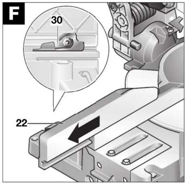
Extending the Fence
(see Figure F)
Before all work on the machine, pull the power plug.

Ensure when extending or enlarging the fence that the functionality of the electro-tool (especially of the swinging guard) is not restricted.
For vertical bevel angle sawing, the fence must be re-positioned.
Loosen the clamping lever 30 and pull the fence extension 22 completely out.
Reclamp with the clamping lever.
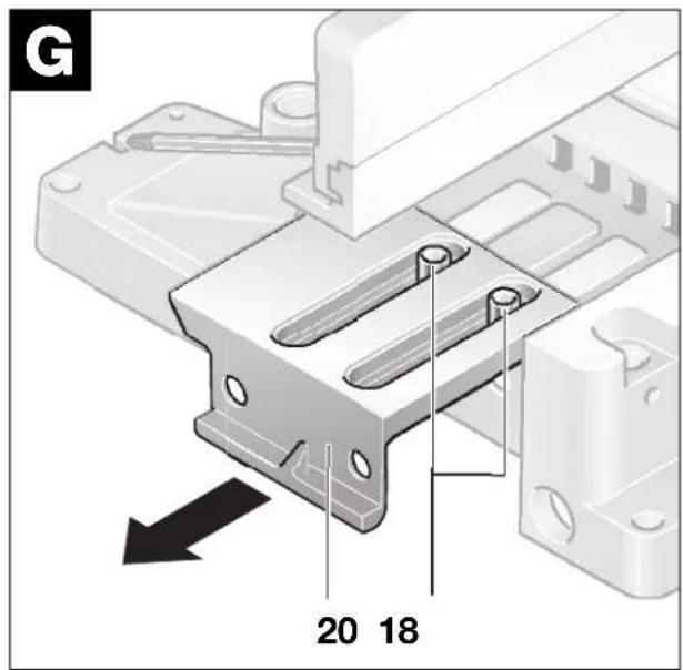
Extending the Saw Table
Before all work on the machine, pull the power plug.
Saw Table Extension
(see Figure G)
Long work pieces must be supported at the free end.
Loosen the two socket-head screws 18 with the Allen key 21 (6 mm) provided.
Pull out the saw table extension 20 to the stop and retighten the socket-head screws.
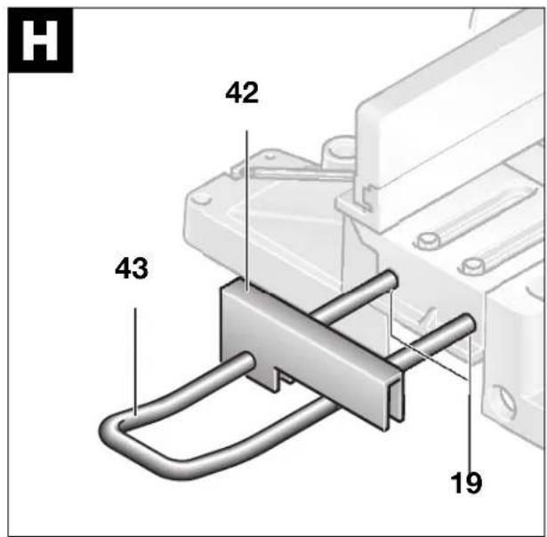
Extension Hoop
(see Figure H)
Slide the extension hoop 43 on either side of the electro-tool to the desired length into the holes 19 provided for this purpose.
Use the stop 42 to saw off work pieces of equal lengths.
Clamping the Work Piece
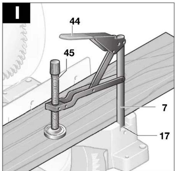
(see Figure 1)
Before all work on the machine, pull the power plug.
To ensure optimum working safety, the work piece must always be firmly clamped.
Do not work with work pieces that are too small to clamp.

When clamping the work piece, do not reach with the fingers under the clamping lever of the quick action clamp.
Press the work piece firmly against the fence 6 and the fence extension 22.
Insert the quick action clamp 7 provided into one of the holes 17 intended for it. Adapt the quick action clamp to the work piece by twisting the threaded rod 45. Press the clamping lever 44 and thereby firmly clamp the work piece.
Adjusting the Miter Angle
Before all work on the machine, pull the power plug.
To ensure precise cuts, the basic adjustments of the electro-tool must be checked and adjusted as necessary after intensive use (see Section „Checking and Adjusting Basic Adjustment“).
Standard Horizontal Miter Angles
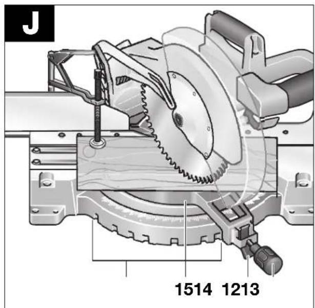
(see Figure J)
For quick and precise setting of often used miter angles, detents 14 are provided on the saw table:
| Left | 0° | 15° 22,5° 31,6° 45° | |
| Right | 15° 22,5° 31,6° 45° |
Place the machine in the working position.
Loosen the locking knob 12 in case it is tightened.
Pull the lever 13 and turn the saw table 15 to the desired miter angle to the right or the left. Release the lever. The lever must be felt to engage in the detent.
Variable Horizontal Miter Angle
The horizontal miter angle can be set in the range from 48^ (left side) to 48^ (right side).
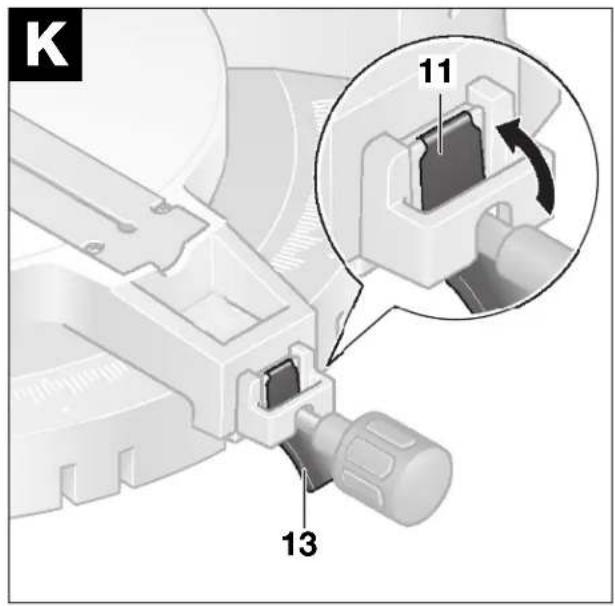
Place the machine in the working position.
Loosen the locking knob 12 in case it is tightened.
Pull the lever 13 and press the locking clamp 11 at the same time until it engages in the groove provide for this purpose (see the illustration K). In this manner, the saw table becomes freely moveable.
Rotate the saw table 15 to the left or right and set the desired miter angle with the aid of the fine scale 10.
Retighten the locking knob 12.
Fine scale
With the fine scale 10, the horizontal miter angle can be set with an accuracy of up to 14^ .
| Desired Setting of the Initial Angle x | Align the Fine Scale Mark (Scale 10) | ... with the Mark (Scale 9) |
| x,25° | 14^ | x + 1° |
| x,5° | 12^ | x + 2° |
| x,75° | 34^ | x + 3° |
Example:
To set to a miter angle of 40.5^ , the 12^ mark of the fine scale 10 must be aligned with the 42^ mark of the scale 9.
Standard Vertical Bevel Angles
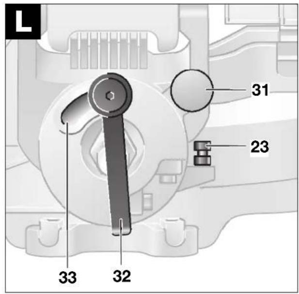
(see Figure L)
For quick and precise setting of often used bevel angles, stops are provided for the angles of 0^ , 33.9^ and 45^ .
Place the machine in the working position.
Loosen the clamping handle 32.
For the standard angles of 0^ or 45^ , swing the tool arm with the handle 1 to the stop at the upper or the lower end of the elongated hole 33.
For the standard angle of 33.9^ , press the setting knob 31 completely in. Then swing the tool arm with the handle 1 until the pin 24 rests against the stop bolt 23.
Retighten the clamping handle 32.
Variable Vertical Bevel Angle
(see Figure M)
The vertical bevel angle can be set in the range from 0^ to 45^ .
Loosen the clamping handle 32.
Swing the tool arm with the handle 1 until the angle indicator 47 points to the desired bevel angle.
Hold the tool arm in this position and retighte clamping handle 32.
Putting into Operation
Switching On and Off
To put into operation, pull the on/off switch 2 in the direction of the handle 1.
For safety reasons, the on/off switch of the machine cannot be locked on but must remain depressed during operation.
For sawing, press in addition the locking lever 3. (see the Figure N)
Only by pressing the locking lever can the tool arm be guided downward.
To switch off the machine, release the on/off switch 2.
0 601 B20 037 (Australia)
To put into operation, slide the switch lock in the direction of the tool arm. Then press the on/off switch 2 and hold it depressed.
For safety reasons, the on/off switch of the machine cannot be locked on but must remain depressed during operation.
To switch off the machine, release the on/off switch 2.
Working Instructions
Before all work on the machine, pull the power plug.
General Sawing Instruction

For all cuts, it must first be ensured the saw blade at no time can come in contact with the fence, screw clamp or other machine parts. Remove possible interfering auxiliary stops or adjust them accordingly.
Do not load the machine so heavily that it comes to a standstill.
Advancing that is too fast reduces considerably the performance capability of the electro-tool and reduces the service life of the saw blade.
Use only sharp saw blades that are suitable for the material being worked.
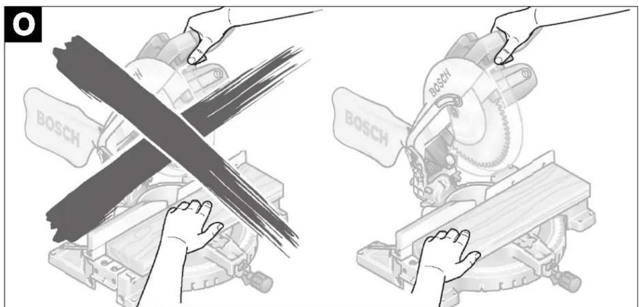
Hand Positioning
Keep fingers, hands and arms away from the rotating saw blade. (see Figure 0)
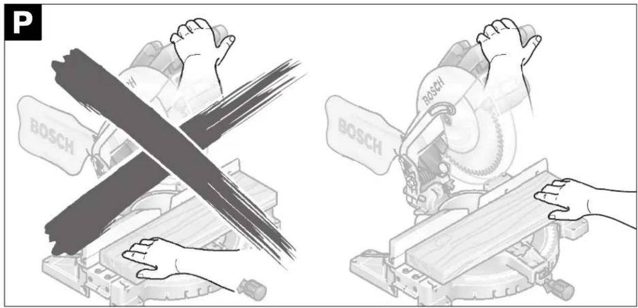
Do not cross your arms when operating the tool arm. (see Figure P)
Special Work Pieces
When sawing curved or round work pieces, they must be especially secured against slipping. At the cutting line, no gap may exist between the work piece and the fence or saw table.
that case necessary, a special fixture must be fabricated.
Table Insert
The red table insert 8 can become worn after long usage of the electro-tool.
Replace a defective table insert.
Place the electro-tool in the working position.
Unscrew the screws 46 with the Phillips screwdriver provided. (see Figure Q)
Insert the new table insert 8 and screw in all screws 46 again.
Set the vertical bevel angle to 0^ and saw a slot in the table insert.
Then set the vertical bevel angle to 45^ and again saw into the slot. With this procedure, it is ensured that the table insert is as close as possible to the teeth of the saw blade without coming in contact with them.
Maximum Work Piece Dimensions
| Sawing Angle Height x Width [mm] | |||
| Miter (Horizontal) | Bevel (Vertical) | At Max. Height | At Max. Width |
| 0° 0° 89 | x 95 61 x 14 | 4 | |
| 45° | 0° 89 x | 67 61 x 101 | |
| 0° | 45° | 46 x 105 | 35 x 144 |
| 45° | 45° | 46 x 95 | 30 x 99 |
Cut-off Sawing
Clamp the work piece firmly according to its dimensions.
Set the desired miter angle.
Switch on the electro-tool.
Press the locking lever 3 and guide the tool arm with the handle 1 slowly downward.
Saw through the work piece with uniform advancing.
Switch off the electro-tool and wait until the saw blade has come to a complete standstill.
Guide the tool arm slowly upward.
Working with Profile Moldings (Floor or Ceiling Moldings)
Profile moldings can be work with two different methods:
- Placed against the fence,
- Lying flat on the saw table.
Always make trial cuts with the miter angle settings first on scrap wood.
Floor Moldings
The following table contains instructions for the working of floor moldings.
| Setting Placed | Against the Fence | 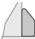 | Lying Flat on the Saw Table | 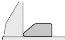 | ||
| Vertical Bevel Angle 0° 45° | ||||||
| Floor Molding Left Side Right Side | Left Side Right Side | |||||
Inner Corner 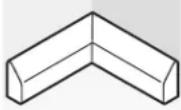 | Horizontal Miter Angle | 45° Left 45° | Right 0° 0° | |||
| Positioning of the Work Piece | Lower edge on the saw table | Lower edge on the saw table | Upper edge on the fence | Lower edge on the fence | ||
| The finished work piece is located ... | ... to the left of the cut | ... to the right of the cut | ... to the left of the cut | ... to the left of the cut | ||
Outer Corner 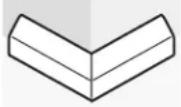 | Horizontal Miter Angle | 45° Right 45° | Left 0° 0° | |||
| Positioning of the Work Piece | Lower edge on the saw table | Lower edge on the saw table | Lower edge on the fence | Upper edge on the fence | ||
| The finished work piece is located ... | ... to the right of the cut | ... to the left of the cut | ... to the right of the cut | ... to the right of the cut | ||
Ceiling Molding (According to US Standard)
When the ceiling molding is to be work lying flat on the saw table, the standard miter angle of 31.6^ (horizontal) and 33.9^ (vertical) must be set. (see Figure R)
The following table contains instructions for the working of ceiling moldings.
| Setting Placed | Against the Fence | 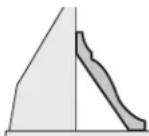 | Lying Flat on the Saw Table | 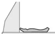 | ||
| Vertical Bevel Angle | 0° | 33,9° | ||||
| Ceiling Molding | Left Side Right Side Left Side Right Side | |||||
Inner Corner 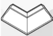 | Horizontal Miter Angle | 45° Right 45° | Left 31.6° | Right 31.6° | Left | |
| Positioning of the Work Piece | Lower edge on the fence | Lower edge on the fence | Upper edge on the fence | Lower edge on the fence | ||
| The finished work piece is located ... | ... to the right of the cut | ... to the left of the cut | ... to the left of the cut | ... to the left of the cut | ||
Outer Corner 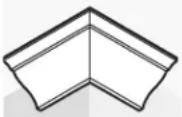 | Horizontal Miter Angle | 45° Left 45° | Right 31.6° | Left 31.6° | Right | |
| Positioning of the Work Piece | Lower edge on the fence | Lower edge on the fence | Lower edge on the fence | Upper edge on the fence | ||
| The finished work piece is located ... | ... to the right of the cut | ... to the left of the cut | ... to the right of the cut | ... to the right of the cut | ||
Checking and Adjusting Basic Adjustment
Before all work on the machine, pull the power plug.
To ensure precise cuts, the basic adjustment must be checked and adjusted as necessary after intensive usage.
Bevel Angle 33,9° (Vertical)
Place the machine in the working position.
Rotate the saw table 15 to the detent 14 for 0°. Loosen the clamping lever 30 and pull the fence extension 22 completely out.
Loosen the clamping handle 32 and press the setting knob 31 completely in. Swing the tool arm with handle 1 until the pin 24 rests against the stop bolt 23.
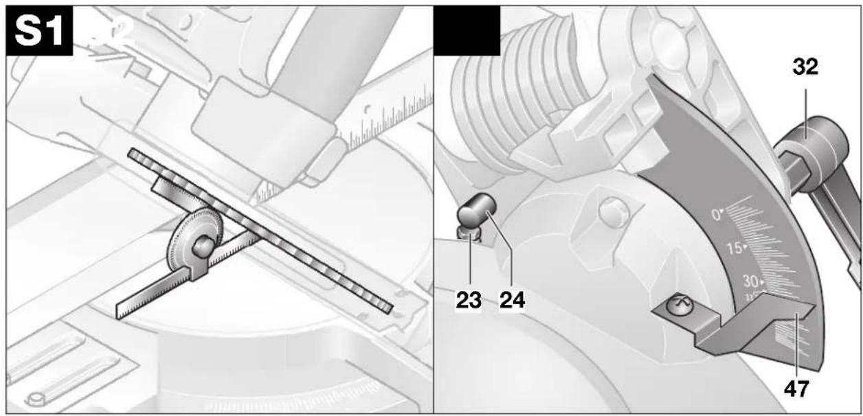
Checking: (see Figure S1)
Place a combination square set to 33,9° on the saw table 15. The leg of the square must be flush with the saw blade over its entire length.
Adjusting: (see Figure S2)
Loosen the locking nut of the stop bolt 23 with the open-ended wrench 36 (12 mm) provided. Turn the stop bolt either in or out until the leg of the square is flush with the saw blade over its entire length.
Retighten the clamping handle 32. Then retighten the locking nut of the stop screw 23.
Fence
Place the electro-tool in the transport position.
Rotate the saw table 15 to the detent 14 for 0°. Loosen the clamping lever 30 and pull the fence extension 22 completely out.
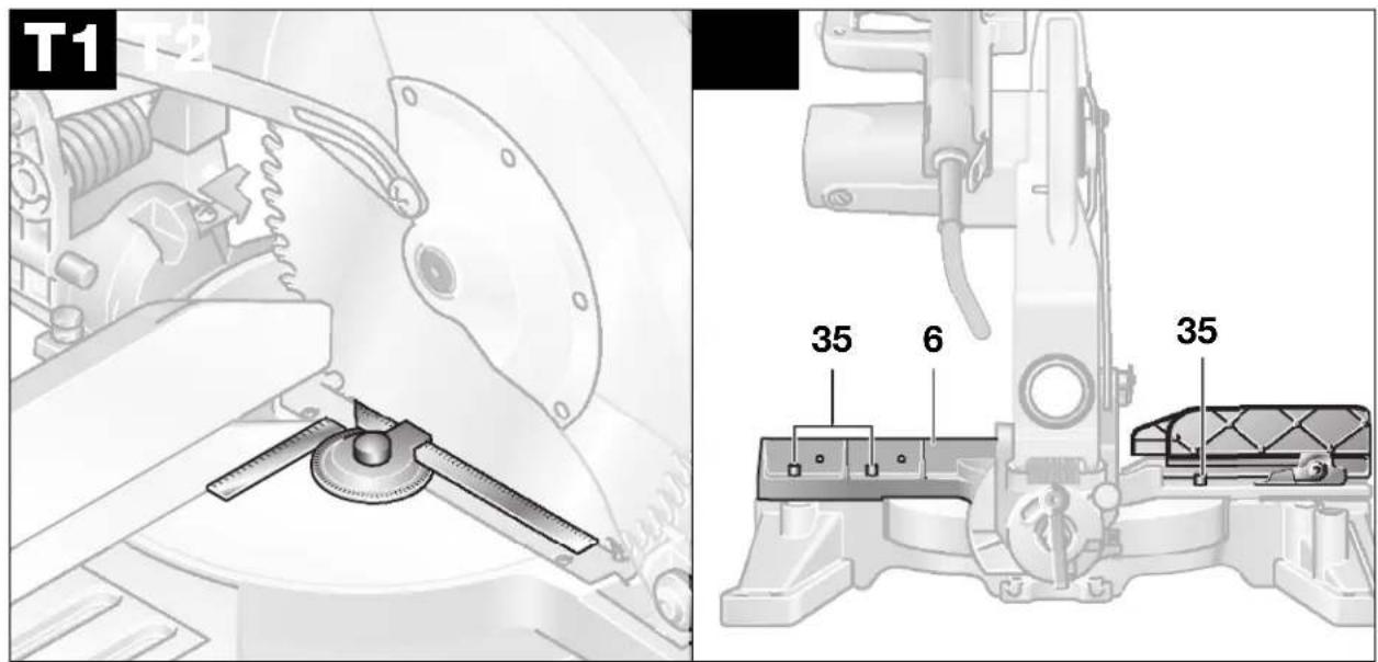
Checking: (see Figure T1)
Set the combination square to 90^ and place it on the saw table 15. The square must be flush with the fence 6 over its entire length.
Adjusting: (see Figure T2)
Loosen all three socket-head screws 35 with the Allen key 21 (6 mm) provided. Rotate the fence 6 until the square is flush with the fence over its entire length. Re-tighten the socket-head screws.
5 MAINTENANCE AND SERVICE
Maintenance
Before all work on the machine, pull the power plug.
Always keep the machine and the ventilation slits clean for efficient and safe working.
The swinging guard must always be able to move freely and close by itself. Therefore, always keep the area around the swinging guard clean.
Remove dust and chips by blowing out with compressed air or with a brush.
Clean the roller 25 regularly.
Should the tool fail in spite of careful ma and testing procedures, have the repairs performed by an authorized customer service location for Bosch Electro-Tools.
For inquiries and spare parts ordering, please include the 10-digit order number on the nameplate of the tool.
Accessories
Saw blade 254 x 30 mm, 40 teeth. . . 2 608 640 438
Saw blade 254 x 25,4 mm, 40 teeth. 2 608 640 459
Saw blade 254 x 16 mm, 40 teeth. . . 2 608 640 466
Saw blade 254 x 25,4 mm, 120 teeth 2 608 640 465
Quick action clamp 2 608 040 205
Table insert 2 607 960 014
Dust bag 2 605 411 187
Extension hoop (356 mm) ..... 2 607 001 911
Angle adapter for dust bag ..... 2 608 601 171
Vacuuming adapter for 35 mm hose . 2 605 702 022
Cafrayingubiagg 2 605 435 019
Disposal
Tool, accessories and packaging should be sorted for environment-friendly recycling.
The plastic components are labeled for categorized recycling.
Service and Customer Advice
Exploded views and information on spare parts can be found under: www.bosch-pt.com
In case of a claim, repair or purchase of replacement parts or in case of queries or other problems please contact your local dealer or Bosch representative.
People's Republic of China
Website: www.bosch-pt.com.cn
Toll Free hotline: 800 8 20 84 84
Sole Agent:
Melchers (H.K.) Ltd.
Hong Kong Representative Office:
Room 1210, Shun Tak Centre, West-Tower,
168 - 200 Connaught Road, Central Hong Kong
Customer Service Hotline: ..... +852 25 89 15 61
Fax +852 25 48 79 14
E-Mail: bosch@melchers.com.hk
Guangzhou Representative Office:
Room 1108, T. P. Plaza,
9/109 Liu Hua Road,
Guangzhou, P.R. China
① +86 20 86 66 87 00
Fax +86 20 86 67 78 45
Postal code: 510010
Bosch After-sales Service Centre Guangzhou:
1/F, East Wing, No. 4 Zeng Cha Road, Guangzhou, P.R. China
①....+86 20 81 75 84 67
① +86 20 81 75 88 73
Fax +86 20 81 75 71 69
Postal code: 510165
E-Mail: bsc@gz.melchers.com.cn
Shanghai Representative Office:
13 Floor, East Ocean Centre,
No. 588 Yanan Road (East),
Shanghai, P.R. China
① +86 21 63 52 88 48
Fax +86 21 63 51 31 38
Postal code: 200001
East Four First Floor Building A,
No. 357 Zhaohua Road,
Shanghai, P.R. China
① +86 21 62 51 13 57
Fax +86 21 62 51 07 60
Postal code: 200050
Beijing Representative Office:
Room 503 – 504, Beijing Tower,
No. 10 Changan Ave (East)
Beijing, P.R. China
① +86 10 65 25 77 75
Fax....+86 10 65 12 35 05
Postal code: 100006
Bosch After-sales Service Centre Beijing:
Room 102 – 103, Beijing Liuliqiao Lanjinglijia,
No. 10 Xisanhuan South Road, Fengtai District,
Beijing, P.R. China
① +86 10 63 36 77 75
① +86 10 63 36 77 76
Fax....+86 10 63 36 77 71
Postal code: 100073
Chongqing Representative Office:
Room 1804, Metropolitan Tower,
68 Zourong Road, Yuzhong District,
Chongqing, P.R. China
① +86 23 63 82 80 40
① +86 23 63 82 80 41
Fax....+86 23 63 82 80 43
Postal code: 400010
E-Mail: bosch@cq.melchers.com.cn
Bosch After-sales Service Centre Chongqing:
166-11 Yuzhou Road, Gaoxin District,
Chongqing, P.R. China
① +86 23 68 57 91 93
Fax +86 23 68 57 90 23
Postal code: 400041
E-Mail: bsc@cq.melchers.com.cn
Wuhan Representative Office:
Rm 202, Unit C, Apartment Bldg.
Yangtze Hotel,1131 Liberation Ave,
Wuhan, P.R. China
① +86 27 83 63 78 85
Fax +86 27 83 62 32 96
Postal code: 430030
E-Mail: bosch@wh.melchers.com.cn
Wuhan After-sales Service Centre:
160 Aomen Road, Jiang'an District,
Hankou, Wuhan, P.R. China
① +86 27 82 44 81 57
Fax +86 27 82 44 81 60
Postal code: 430015
Makati City 1200, Metro Manila
Philippines
① +63 2 8 17 32 31
www.bosch.com.ph
Malaysia
Robert Bosch (SEA.) Pte. Ltd.
No. 8a, Jalan 13/6
Selangor Darul Ehsan
Petaling Jaya 46200
Malaysia
① +60 3 79 58 30 00
Fax (EW Dept.)....+60 3 79 58 38 38
www.bosch.com.sg
Thailand
Robert Bosch Ltd.
Liberty Square Building
No. 287, 11 Floor
Silom Road, Bangrak
Bangkok 10500
① +66 2 6 31 18 79 - 18 88 (10 lines)
Fax +66 2 2 38 47 83
Robert Bosch Ltd., P. O. Box 2054
Bangkok 10501, Thailand
Bosch Service - Training Centre
2869-2869/1 Soi Ban Kluay
Rama IV Road (near old Paknam Railway)
Prakanong District
10110 Bangkok
Thailand
① +66 2 6 71 78 00 - 4
Fax +66 2 2 49 42 96
Fax +66 2 2 49 52 99
Singapore
Robert Bosch (SEA.) Pte. Ltd.
38 C Jalan Pemimpin
Singapore 915701
Republic of Singapore
① +65 3 50 54 94
Fax....+65 3 50 53 27
www.bosch.com.sg
Vietnam
Ho Chi Minh City
Robert Bosch (SEA) Pte Ltd
Resident Representative Office HCMC
Tacasin Business Centre, 2nd Floor
243-243B Hoang Van Thu P.1
Tan Binh District
Vietnam
① +84 8 8 47 87 64
Fax....+84 8 8 47 83 28
Australia
Robert Bosch Australia L.t.d.
RBAU/SPT2
1555 Centre Road
P.O. Box 66 Clayton
3168 Clayton/Victoria
① 1800804777
Fax 1800819520
CustomerSupportSPT@au.bosch.com
www.bosch.com.au
Specifications subject to change without notice.
Argentina
RBAR
① 0810 555 2020
Bolivia
HANSA
① +59 12 314 445
Brasil
RBLA
① 0800 70 45 446
Chile
EMASA
① 600 7378 4832
Colômbia
INNOVATEQ
① +571 629 4284
Costa Rica
MADISA
① +506 233 6255
Equador
ELECTRO DIESEL
① +593 4 220 2688
El Salvador
PROYESA
① +503 221 0666
Guatelmala
EDISA
① +502 2 331 7227
Honduras
CHIPS
① +504 556 9781
México
RBMX
① +55 5284 3000
Paraguai
CHISPA
① +595 21 553 315
Peru
AUTOREX
① +51 1 475 5453
Venezuela
RBVE
① +58 212 207 4511
Specifications subject to change without notice.
| esquerda | 0^ | 15^ 22,5^ 31,6^ 45^ | |
| direita | 15^ 22,5^ 31,6^ 45^ |
Robert Bosch Korea Mechanics and Electronics Ltd.
전동공구 사업부
| kiri | 0^ | 15^ | 22,5^ | 31,6^ | 45^ |
| kanan | 15^ | 22,5^ | 31,6^ | 45^ |
| trái | 0^ | 15^ | 22,5^ | 31,6^ | 45^ |
| phải | 15^ | 22,5^ | 31,6^ | 45^ |
( Regions should be synthesiser)
Installation stationnaire (cf. figure D1)
Installation de fortune (cf. figure D2)
Aspiration interne (cf. figure E)
Réglage : (cf. figure S2)
Réglage : (cf. figure T2)
natural_image
Black and white striped flag with no text or symbols

1 609 929 E91 (04.10) PS/180 Printed in China

- GENERAL SAFETY RULES
- FOR ELECTRIC TOOLS
- WARNING
- Work Area
- Electrical Safety
- Personal Safety
- Power Tool Handling and Usage
- Service
- SPECIFIC SAFETY RULES
- FOR COMPOUND MITER SAWS
- SYMBOLS
- FUNCTION
- Intended Use
- Noise/Vibration Information
- Wear ear protection!
- Product Elements
- OPERATING INSTRUCTIONS
- Transport Safety
- Securing the Machine (Transport Position)
- Releasing the Machine (Working Position)
- Mounting the Locking Knob
- Changing the Tool
- Removing the Saw Blade
- Mounting the Saw Blade
- Stationary or Flexible Mounting
- Stationary Mounting
- Flexible Mounting
- Dust/Chip Extraction
- Integrated Dust Extraction
- External Dust Extraction
- Extending the Fence
- Extending the Saw Table
- Saw Table Extension
- Extension Hoop
- Clamping the Work Piece
- Adjusting the Miter Angle
- Standard Horizontal Miter Angles
- Variable Horizontal Miter Angle
- Fine scale
- Example:
- Standard Vertical Bevel Angles
- Variable Vertical Bevel Angle
- Putting into Operation
- Switching On and Off
- For safety reasons, the on/off switch of the machine cannot be locked on but must remain depressed during operation.
- 601 B20 037 (Australia)
- Working Instructions
- General Sawing Instruction
- Hand Positioning
- Special Work Pieces
- Table Insert
- Cut-off Sawing
- Working with Profile Moldings (Floor or Ceiling Moldings)
- Floor Moldings
- Ceiling Molding (According to US Standard)
- Checking and Adjusting Basic Adjustment
- Before all work on the machine, pull the power plug.
- Bevel Angle 33,9° (Vertical)
- Checking: (see Figure S1)
- Adjusting: (see Figure S2)
- Fence
- Checking: (see Figure T1)
- Adjusting: (see Figure T2)
- MAINTENANCE AND SERVICE
- Maintenance
- Accessories
- Disposal
- Service and Customer Advice
- People's Republic of China
- Hong Kong Representative Office:
- Guangzhou Representative Office:
- Bosch After-sales Service Centre Guangzhou:
- Shanghai Representative Office:
- Beijing Representative Office:
- Bosch After-sales Service Centre Beijing:
- Chongqing Representative Office:
- Bosch After-sales Service Centre Chongqing:
- Wuhan Representative Office:
- Wuhan After-sales Service Centre:
- Malaysia
- Thailand
- Singapore
- Vietnam
- Australia
- Specifications subject to change without notice.
- Argentina
- Bolivia
- Brasil
- Chile
- Colômbia
- Costa Rica
- Equador
- El Salvador
- Guatelmala
- Honduras
- México
- Paraguai
- Peru
- Venezuela
- Réglage : (cf. figure S2)
- Réglage : (cf. figure T2)
Brand : BOSCH
Model : GCM 10 SD Professional
Category : Saw