ELPMBPJG - Video projector EPSON - Free user manual and instructions
Find the device manual for free ELPMBPJG EPSON in PDF.

User questions about ELPMBPJG EPSON
0 question about this device. Answer the ones you know or ask your own.
Ask a new question about this device
Download the instructions for your Video projector in PDF format for free! Find your manual ELPMBPJG - EPSON and take your electronic device back in hand. On this page are published all the documents necessary for the use of your device. ELPMBPJG by EPSON.
USER MANUAL ELPMBPJG EPSON
INSTALLATION INSTRUCTIONS
Milestone AV Technologies and its affiliated corporations and subsidiaries (collectively "Milestone"), intend to make this manual accurate and complete. However, Milestone makes no claim that the information contained herein covers all details, conditions or variations, nor does it provide for every possible contingency in connection with the installation or use of this product. The information contained in this document is subject to change without notice or obligation of any kind. Milestone makes no representation of warranty, expressed or implied, regarding the information contained herein. Milestone assumes no responsibility for accuracy, completeness or sufficiency of the information contained in this document.

IMPORTANT SAFETY INSTRUCTIONS

WARNING: A WARNING alerts you to the possibility of serious injury or death if you do not follow the instructions.

CAUTION: A CAUTION alerts you to the possibility of damage or destruction of equipment if you do not follow the corresponding instructions.

WARNING: Failure to read, thoroughly understand, and follow all instructions can result in serious personal injury, damage to equipment, or voiding of factory warranty! It is the installer's responsibility to make sure all components are properly assembled and installed using the instructions provided.

WARNING: Failure to provide adequate structural strength for this component can result in serious personal injury or damage to equipment! It is the installer's responsibility to make sure the structure to which this component is attached can support five times the combined weight of all equipment. Reinforce the structure as required before installing the component.

WARNING: Exceeding the weight capacity can result in serious personal injury or damage to equipment! It is the installer's responsibility to make sure the combined weight of all components attached to the ELPMBPJG does not exceed 25 lbs (11.4 kg).

WARNING: Use this mounting system only for its intended use as described in these instructions. Do not use attachments not recommended by the manufacturer.

WARNING: Never operate this mounting system if it is damaged. Return the mounting system to a service center for examination and repair.

WARNING: Do not use this product outdoors.
IMPORTANT ! : The ELPMBPJG is designed to be:
- mounted to 2'' × 4'' wood stud ceiling joists using supplied hardware; or
- mounted to a concrete ceiling with a minimum thickness of 8" and a maximum drywall covering of 5/8" using 5/16" × 2.75" lag bolts (included) with UX10 OR AF8 anchors (not included)
--SAVE THESE INSTRUCTIONS--
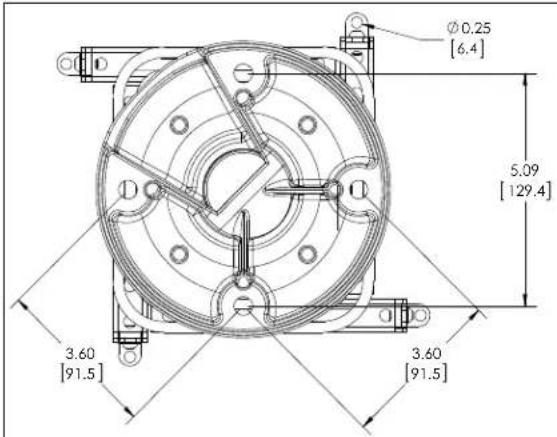
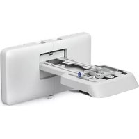
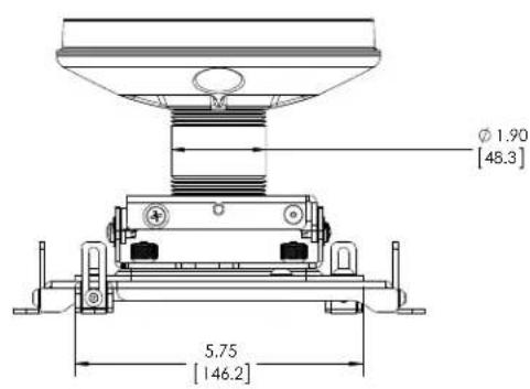
DIMENSIONS
0.90 [23.0] HEIGHT ADJUSTMENT
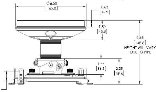
DIMENSIONS: INCHES [MILLIMETERS]
TOOLS REQUIRED FOR INSTALLATION
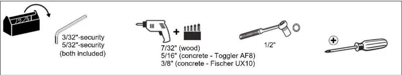
HARDWARE REQUIRED FOR CONCRETE INSTALLATION (not included)
Fischer UX10 concrete anchors OR Toggler AF8 concrete anchors (Qty. 4)
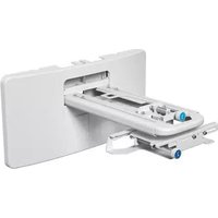
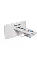
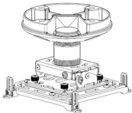
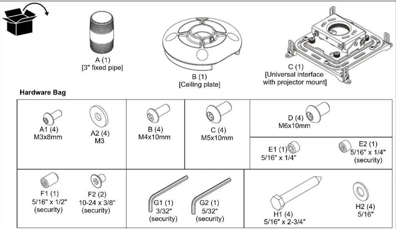
PARTS
INSTALLATION

WARNING: Failure to provide adequate structural strength for this component can result in serious personal injury or damage to equipment! It is the installer's responsibility to make sure the structure to which this component is attached can support five times the combined weight of all equipment. Reinforce the structure as required before installing the component.
Installing Ceiling Plate
- Determine mounting location.
IMPORTANT ! : This will require knowing the lens to screen distance. See projector specifications for details on determining this distance
NOTE: Proceed to Installing to Wood Joists or Installing to Solid Concrete section dependent upon whether the ceiling plate will be installed to wood joists or concrete.
Installing to Wood Joists
- Using ceiling plate (B) as a template, mark locations of two pilot holes. (See Figure 1) Ensure the following:
- OPPOSITE holes are used in plate (B), and
- Marks are in the center of wood joist.
NOTE: Drywall not shown for clarity.
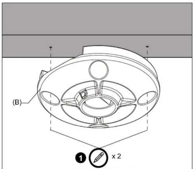
Figure 1
- Drill 7/32'' x 2-3/4'' pilot holes into narrow side of wood joist. Ensure pilot holes are straight.
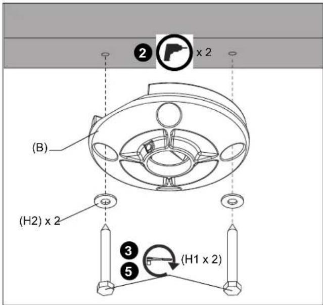
Figure 2
- Loosely install two (minimum) 5/16" x 2-3/4" lag screws (H1) through 5/16" washers (H2) and ceiling plate (B), into wood joist. (See Figure 2)
NOTE: Do not tighten ceiling plate (B) against ceiling at this time to accommodate cable installation.
NOTE: Two additional washers and lag screws are provided.
- Route cables through channel in ceiling plate (B). (See Figure 3)
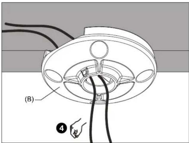
Figure 3
- Tighten lag screws (F). (See Figure 2)
Installing to Solid Concrete
- Using the ceiling plate (B) as a guide, mark mounting hole locations (two minimum) on ceiling. (See Figure 4)
IMPORTANT ! : Ensure that OPPOSITE holes are used in plate (B).
-
Drill two (minimum) pilot holes as follows: (See Figure 4)
-
Toggle AF8: 5/16" x 2-3/4"
Fischer UX10:3/8" x 2-3/4"
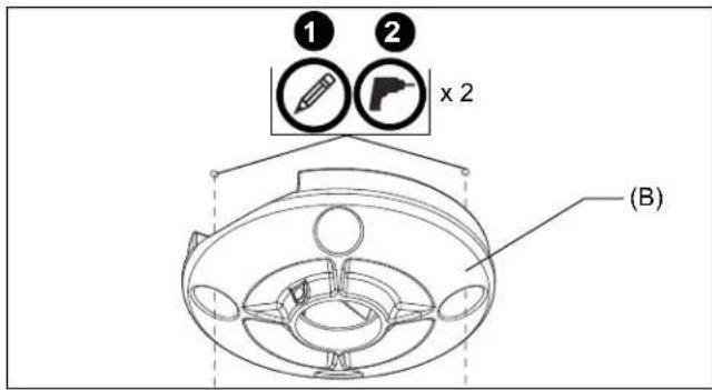
Figure 4
- Align two mounting holes in ceiling plate with two pilot holes.

WARNING: Anchors (not provided) must be installed into structurally sound solid concrete. Installation into hollow concrete block, mortar, or concrete that exhibits cracking, spalling, or other defects may result in failure of anchor and serious personal injury or damage to equipment.
- Install two Fischer UX10 or Toggler AF8 concrete anchors (not included) into pilot holes until flush with mounting surface. (See Figure 5)
- Loosely secure ceiling plate (B) to structure using two (minimum) 5 / 16'' x 2-3/4" lag bolts (H1). (See Figure 5)
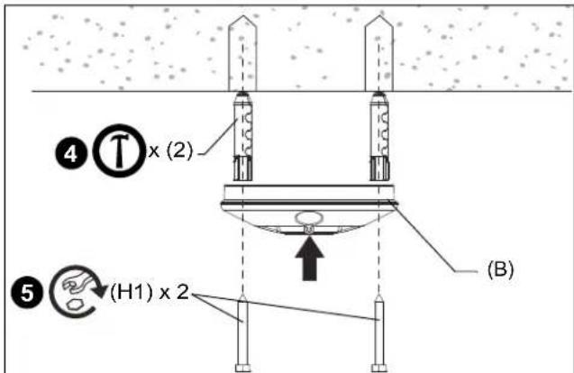
Figure 5
NOTE: Do not tighten ceiling plate (B) against ceiling at this time to accommodate cable installation.
- Route cables through channel in ceiling plate (B). (See Figure 6)
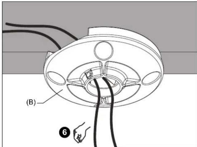
Figure 6
- Tighten lag bolts. (See Figure 5)
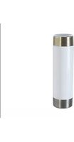
Installing Fixed Pipe

WARNING: Exceeding the weight capacity can result in serious personal injury or damage to equipment! It is the installer's responsibility to make sure the combined weight of all components attached to the ELPMBPJG does not exceed 25 lbs (11.4 kg).
- Install 3^ fixed pipe (A) into threaded collar of ceiling plate (B) until tight, with a minimum of four threads engaged. (See Figure 7)
-
Secure extension column by one of the following methods: (See Figure 7)
-
Install one 5 / 16'' × 1 / 4'' set screw (E1) into threaded hole in ceiling plate (B), tightening firmly against column.
- OPTIONAL: Using 5/32" security hex key (G2), install one 5 / 16''× 1 / 4'' security set screw (E2) into threaded hole in ceiling plate (B), tightening firmly against column.
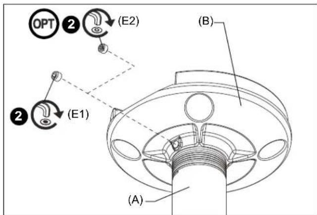
Figure 7
Installing Projector Mount

WARNING: IMPROPER INSTALLATION CAN RESULT IN SERIOUS PERSONAL INJURY OR DAMAGE TO EQUIPMENT! Structural members MUST be capable of supporting five times the combined weight of all equipment being mounted.
- Loosen (but do NOT remove) four thumb nuts on universal interface, and remove projector mount from universal interface. (See Figure 8)
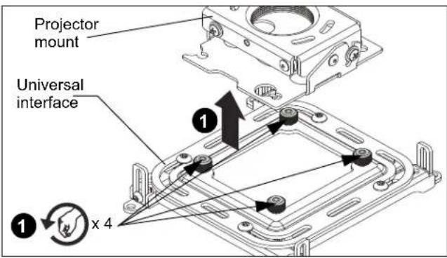
Figure 8
- Align projector mount with end of 3^ fixed pipe (A), and thread projector mount up onto pipe by turning counterclockwise until hand tight, with a minimum of four threads engaged. (See Figure 9)
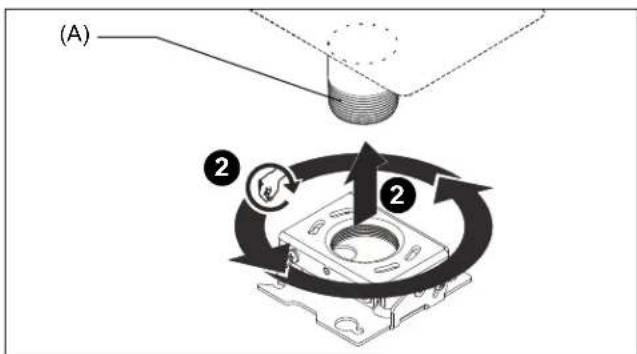
Figure 9
Rough Alignment of Projector Mount
- Turn projector mount clockwise or counter-clockwise until front of mount is facing target.
IMPORTANT ! : When projector mount is properly positioned, the set screw access hole should be pointing directly at target. (See Figure 10)
-
Secure projector mount to pipe by one of the following methods:
-
Turn set screw (shipped installed in projector mount) with the 5/32" hex key until tight.
- OPTIONAL: Remove existing set screw (shipped installed in projector mount) with the 5/32'' hex key (G2), and install the 5/16'' × 1/2'' security set screw (F1) using the 5/32'' hex key (G2).

CAUTION: DO NOT OVERTIGHTEN! Overtightening set screw can damage pipe threads.
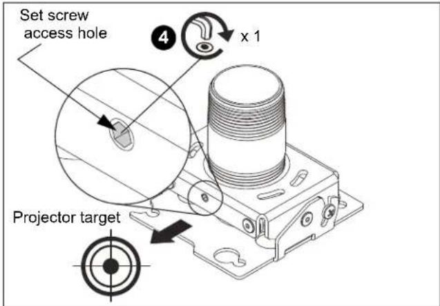
Figure 10
Attaching Universal Interface to Projector
- Determine the distance between the mounting holes on the projector. (See Figure 11)
NOTE: There is not a standard mounting hole configuration pattern for projectors. The universal interface legs can be configured to match the mounting holes on the projector.
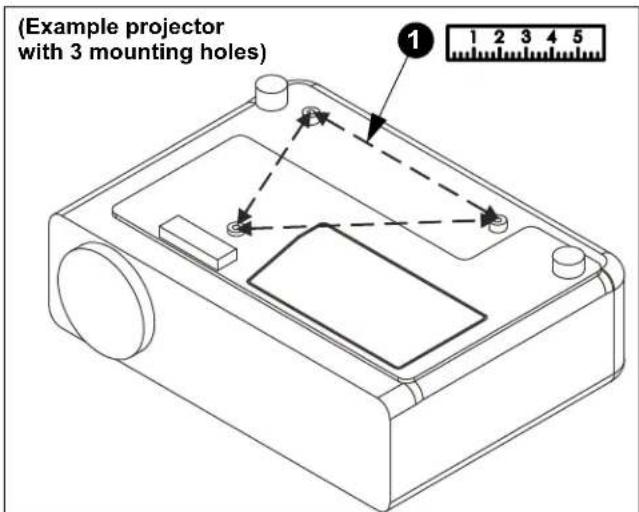
Figure 11
- Loosen, but do NOT remove, the screws holding the legs to the universal interface. (See Figure 12)
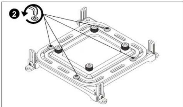
Figure 12
NOTE: Remove one security screw, hex nut and leg if the projector only has three mounting holes. (See Figure 13)
NOTE: The universal interface legs may be adjusted into numerous configurations. The interface legs may be extended out or brought into the center of the interface.
NOTE: If it is not possible to align the adjustable legs with the mounting hole pattern on the projector, a leg or legs may be moved and/or removed so that the interface may be aligned using a horizontal slot.
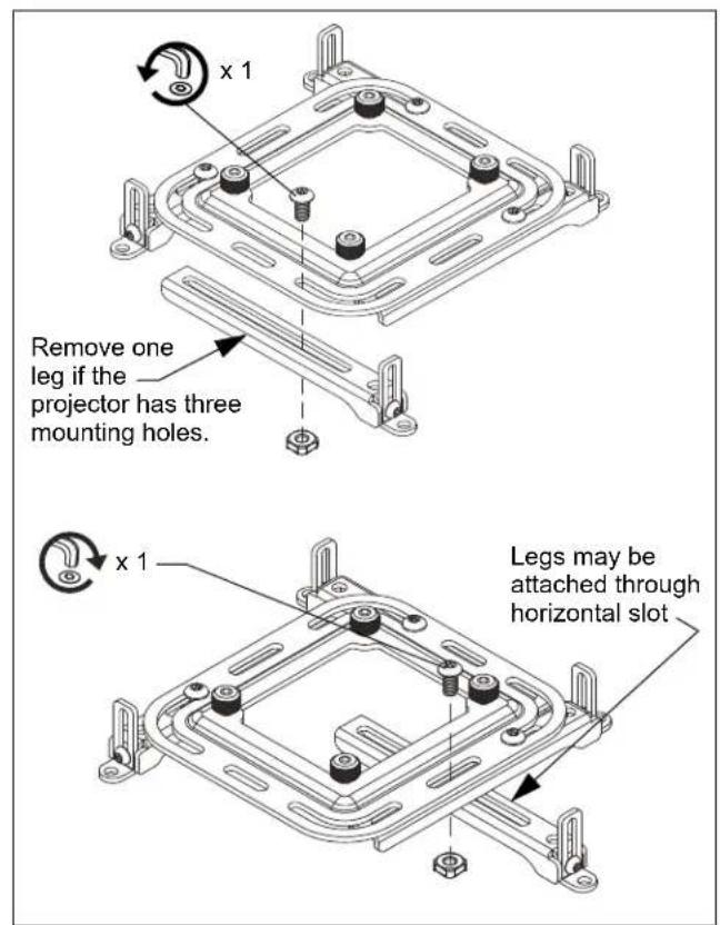
Figure 13
- Place the universal interface on the projector.
- Adjust legs on interface as needed to align the legs with projector mounting holes.
- Secure universal interface to the projector by selecting the security screws (A1-D) that fit the mounting holes in the projector.
NOTE: If using M3 x 8mm security screws (A1), also use the M3 washers (A2).
- Attach the universal interface to the projector either through the bracket feet, or directly through the legs. (See Figure 14)
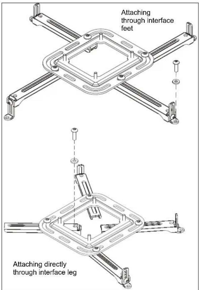
Figure 14
- Do NOT tighten screws at this time.
Adjusting Universal Interface Feet

WARNING: IMPROPER INSTALLATION CAN LEAD TO PROJECTOR FALLING CAUSING SERIOUS PERSONAL INJURY OR DAMAGE TO EQUIPMENT! DO NOT substitute hardware. Use only hardware provided by the manufacturer and make certain all hardware is properly tightened.
- Adjust the feet on the universal interface to the proper height.
NOTE: Foot height is adjusted for a variety of reasons including: ventilation, uneven projector surface, or to level the interface bracket mounting plate.
- Visually check the height of the mounting plate on the interface.
- Loosen screw and adjust foot that is attached to adjustable leg. The foot may be removed and reattached to allow more adjustment, if necessary. (See Figure 15)
- Adjust foot height as needed. If necessary, use a level to verify that the universal interface mounting plate is level.
- Tighten screw.
- Repeat procedure for each foot as needed until the feet on the universal interface are adjusted properly.
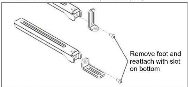
Figure 15
Install Projector

WARNING: IMPROPER INSTALLATION CAN LEAD TO PROJECTOR FALLING RESULTING IN SERIOUS PERSONAL INJURY OR DAMAGE TO EQUIPMENT. DO NOT substitute hardware. Use only the hardware provided by the manufacturer.
IMPORTANT ! : For security attachment of projector, proceed to Step 1. For easy-release attachment of projector, proceed to Step 2.
- Remove two thumb nuts and Phillips screws from opposite corners of universal interface. (See Figure 16)
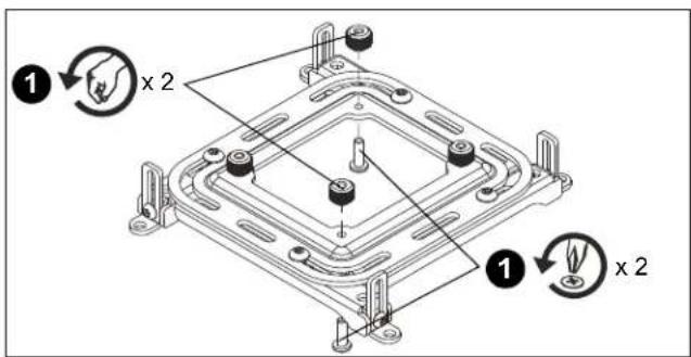
Figure 16
- Orient projector attached to universal interface with projector mount. (See Figure 17)
- Lift projector so that screws with thumb nuts are aligned with mounting slots in projector mount.
- Slide projector with universal interface into mounting slots in projector mount until screws are seated against the back of mounting slots.

WARNING: IMPROPER INSTALLATION CAN LEAD TO PROJECTOR FALLING RESULTING IN SERIOUS PERSONAL INJURY OR DAMAGE TO EQUIPMENT. Make certain mounting slots in projector mount slide under thumb screws and that screws are seated in the back of slots.
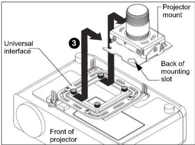
Figure 17
-
Secure projector to mount (See Figure 18) by either:
-
Turning four thumb nuts until tight; or
SECURITY ATTACHMENT ONLY: Tightening two remaining thumb nuts, and installing two flat head security screws (F2) into corners where thumb nuts were previously removed.
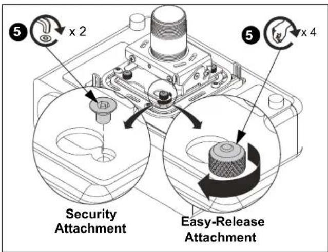
Figure 18
ADJUSTMENTS
YAW Adjustment
- Loosen yaw adjustment screw using the 5/32" hex key. (See Figure 19)
NOTE: Yaw is only adjustable when attached to a threaded pipe.

WARNING: Do not turn the projector to the end of the pipe threads. The projector, universal interface and projector mount will fall from the pipe if it is unthreaded too far! A minimum of four threads MUST be engaged in order to ensure a secure connection!
- Adjust projector by turning the projector on the pipe to the desired yaw position.
- Tighten yaw adjustment locking screw using the 5/32'' hex key.
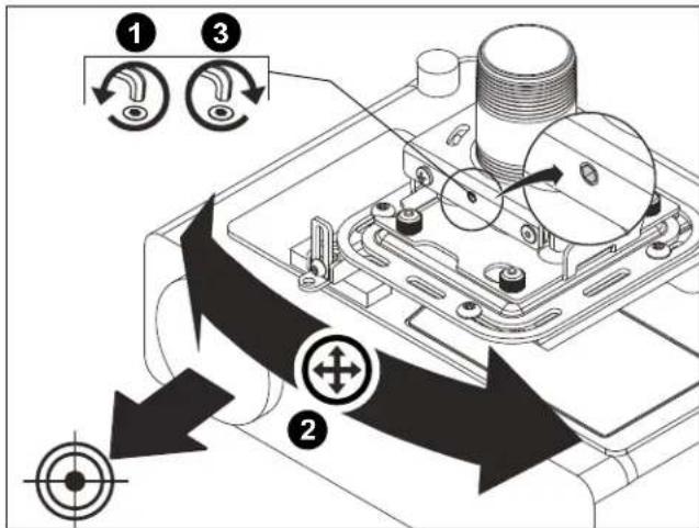
Figure 19
Pitch Adjustment
- Loosen pitch adjustment locking screw on each end of the RSA projector mount using a #2 Phillips screwdriver.
- Adjust projector angle to desired pitch. (See Figure 20)
- Tighten pitch adjustment locking screw on each end of the RSA projector mount using a #2 Phillips screwdriver.

Figure 20
Roll Adjustment
- Loosen roll adjustment locking screw on each side of the RSA projector mount using a #2 Phillips screwdriver.
- Adjust projector to desired roll position. (See Figure 21)
- Tighten roll adjustment locking screw on each side of the RSA projector mount using a #2 Phillips screwdriver.
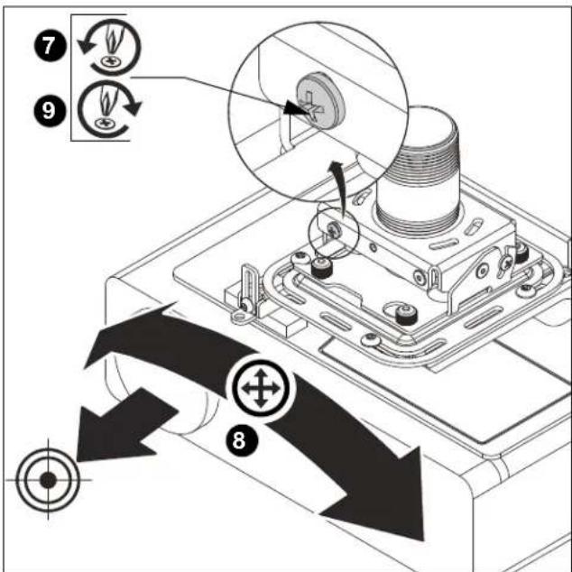
Figure 21
LIMITED WARRANTY
With the exception of electrical products, Milestone warrants its products to be free of defects in material and workmanship for 10 years. All warranties are in effect beginning the date the product was invoiced by Milestone. Electrical mechanisms (such as lift products) have a 1-year limited warranty. All warranties are in effect for the original purchaser only. Milestone disclaims liability for any modifications, improper installation and/or installations over the specified weight capacity. Milestone also disclaims liability for any modifications made to electrical mechanisms, improper installation, incorrect voltage connection and/or installations over the stated weight capacity. All Electrical Mechanisms are intended for indoor use only and failure to comply will void warranty. Milestone's sole warranty obligation to the owner of its products is to repair or replace (at Milestone's discretion) defective products at no charge to the original purchaser within the warranty period. The purchaser is responsible for returning the product to Milestone via prepaid shipping. To the maximum extent permitted by applicable law, Milestone disclaims any other warranties, express or implied, including warranties of fitness for a particular purpose and warranties of merchantability. Milestone will not be liable for any damages whatsoever arising out of the use or inability to use Milestone products, even if Milestone has been advised of the possibility of such damages. Milestone bears no responsibility for incidental or consequential damages. This includes, but is not limited to, any labor charges for the repair of Milestone products performed by someone other than a Milestone employee. Because some states and jurisdictions do not allow the exclusion or limitation of liability for consequential or incidental damages, the above limitation may not apply. Milestone will not be responsible for damage to Milestone products caused by misuse, abuse, failure to properly package the product for return to Milestone or for damage caused by carriers during shipment to or from Milestone. Any repairs to Milestone products required due to misuse, abuse or shipping damage or repairs of defective Milestone product outside the warranty period will be performed at the current rates established by Milestone for factory service.
Distributed by:
Epson America, Inc.
3840 Kilroy Airport Way
Long Beach, CA 90806
Manufactured by:
Milestone AV Technologies
A 6436 City West Parkway, Eden Prairie, MN 55344
P 866.977.3901
F 877.894.6918
E info@milestone.com (Tech Support 7:00am - 7:00pm CST)
www.milestone.com
8800-002741 Rev00
08/15

CLAUSE DE NON-RESPONSABILITÉ
A 6436 City West Parkway, Eden Prairie, MN 55344
T 866.977.3901
F 877.894.6918
E info@milestone.com (Assistance technique 7h00 - 19h00 HNC)
www.milestone.com
8800-002741 Rév00
08/15

DESCARGO DE RESPONSABILIDAD
D 6436 City West Parkway, Eden Prairie, MN 55344
T 866.977.3901
F 877.894.6918
C info@milestone.com (Servicio专业技术: 7:00 - 19:00 CST)
www.milestone.com
8800-002741 Rev00
08/15

AVISO LEGAL
A 6436 City West Parkway, Eden Prairie, MN 55344
P 866.977.3901
F 877.894.6918
E info@milestone.com (Suporte professionnel 7:00am - 7:00pm CST)
www.milestone.com
8800-002741 Rev00
08/15

Distributed by:
Epson America, Inc.
3840 Kilroy Airport Way
Long Beach, CA 90806
Manufactured by:
Milestone AV Technologies
A 6436 City West Parkway, Eden Prairie, MN 55344
P 866.977.3901
F 877.894.6918
E info@milestone.com (Tech Support 7:00am - 7:00pm CST)
www.milestone.com
8800-002741 Rev00
08/15