
ELPMB46 - Video projector EPSON - Free user manual and instructions
Find the device manual for free ELPMB46 EPSON in PDF.
| Product Type | Wall mount for projector |
| Brand | Epson |
| Model | ELPMB46 |
| Total support weight (including accessories) | Approximately 7.2 kg (15.9 lb) |
| Maximum load capacity | 9.5 kg (20.9 lb) |
| Vertical sliding adjustment range | ± 38 mm (1.5 in) |
| Horizontal sliding adjustment range | ± 45 mm (1.8 in) |
| Front/back sliding adjustment range | 13 to 350 mm (0.5 to 13.8 in) |
| Horizontal roll adjustment range | ± 3° |
| Horizontal rotation adjustment range | ± 8° |
| Vertical tilt adjustment range | ± 3° |
| Wall plate dimensions (assembled) | Approximately 496 mm (19.5 in) width |
| Material | Steel (estimated) |
| Mounting type | Wall, on concrete |
| Required fasteners (not included) | M10 x 60 mm anchors (at least 3) |
| Recommended tools | #3 Phillips screwdriver, 13 mm open-end wrench, M4 hex key |
| Projector compatibility | BrightLink and PowerLite (specific models, see manual) |
| Warranty | 2-year limited |
| Maintenance | Regular inspection of screws and parts |
| Safety | Installation by two qualified technicians, do not modify the mount |
Frequently Asked Questions - ELPMB46 EPSON
User questions about ELPMB46 EPSON
0 question about this device. Answer the ones you know or ask your own.
Ask a new question about this device
Download the instructions for your Video projector in PDF format for free! Find your manual ELPMB46 - EPSON and take your electronic device back in hand. On this page are published all the documents necessary for the use of your device. ELPMB46 by EPSON.
USER MANUAL ELPMB46 EPSON
natural_image
Technical line drawing of an electronic device internal structure, showing internal components and housing (no text or symbols)About This Installation Guide
This guide describes how to mount the ultra-short-throw projectors listed below to a wall using the Epson® ELPMB46 wall mount.
The following projectors are covered by this guide:
- BrightLink® 475Wi/480i/485Wi/575Wi/575Wi+/585Wi/585Wi+/595Wi/595Wi+/675Wi+/685Wi/685Wi+/695Wi/695Wi+/696Ui/697Ui
• BrightLink Pro 1410Wi/1420Wi/1430Wi/1450Ui/1460Ui
• PowerLite® 470/475W/480/485W/570/575W/580/585W/675W/680/685W
Safety Instructions
For your safety, read all the instructions in this guide before using the wall mount. Incorrect handling that ignores instructions in this guide could damage the wall mount or could result in personal injury or property damage. Keep this installation guide on hand for future reference.
Read the safety instructions in the User's Guide for your projector and follow the instructions in this document.
Explanation of Symbols
The warning marks shown below are used throughout this installation guide to prevent personal injury or property damage. Make sure you understand these warnings when reading this installation guide.
| Warning | This symbol indicates information that, if ignored, could possibly result in personal injury or even death due to incorrect handling. |
| Caution | This symbol indicates information that, if ignored, could possibly result in personal injury or physical damage due to incorrect handling. |
 | This symbol indicates related or useful information. |
| [SACZ] | Symbol indicating an action that must not be done |
 | Symbol indicating an action that should be done |
Safety Precautions for Installation
 Warning Warning | |
| The wall mount is designed specifically for mounting a projector to a wall. If anything other than a projector is mounted, the weight may result in damage. |  |
| If the wall mount falls, it could cause personal injury or property damage. | |
| The installation work (wall mounting) should be performed by specialists who have technical knowledge and ability. Incomplete or incorrect installation could cause the wall mount to fall and cause personal injury or property damage. |  |
| Handle the power cord carefully.Incorrect handling may cause fire or electric shock. Observe the following precautions when handling:Do not handle the power plug with wet hands.Do not use a power cord that is damaged or modified.Do not pull the power cord with too much force when routing the cable through the wall mount. |  |
 | |
| Do not install the wall mount in a place where it might be subjected to vibration or shock. Vibration or shock could cause damage to the projector or mounting surface. It could also cause the wall mount or projector to fall and cause personal injury or property damage. | |
| The installation work should be performed by at least two qualified service personnel. If you need to loosen any screws during installation, be careful not to drop the wall mount. If the wall mount or projector falls, it could cause personal injury or property damage. | |
| Install the wall mount so that it can sufficiently support the weight of the projector and wall mount, and resist any horizontal vibration. Use M10 nuts and bolts and make sure to use appropriate wall anchors for your wall type. Nuts and bolts smaller than M10 could cause the wall mount to fall. Epson accepts no responsibility for any damage or injury caused by lack of wall strength or inadequate installation. | |
| When you mount the projector on the wall with the wall mount, the wall must be strong enough to hold the projector, the wall mount, as well as the Control Pad and the Touch Unit, if applicable. This wall mount should be installed on a concrete wall. Confirm the weight of the projector, the wall mount, the Control Pad, and the Touch Unit before installation, and maintain the strength of the wall. If the wall is not strong enough, reinforce the wall before installation. | |
| Inspect the wall mount on a regular basis to ensure there are no broken parts or loose screws. If there are any broken parts, stop using the wall mount immediately. If the wall mount or projector falls, it could cause personal injury or property damage. | |
| Never modify the wall mount. | |
| Do not hang on the wall mount or hang a heavy object on the wall mount. If the projector or wall mount falls, it could cause personal injury or property damage. | |
| Do not use adhesives, lubricants, or oils to install or adjust the wall mount. If you use adhesives to prevent the screws from loosening or things such as lubricants or oils on the part of the projector attached to the slide plate, the case may crack and cause the projector to fall, resulting in personal injury or property damage. | |
| Tighten all screws firmly after adjustment. Otherwise, the projector or wall mount may fall and cause personal injury or property damage. | |
| Never loosen the bolts and nuts after installation. Confirm that the screws have not become loose on a regular basis. If you find any loose screws, tighten them firmly. Otherwise, the projector or wall mount may fall and cause personal injury or property damage. | |
| When performing wiring, make sure the cable does not come into contact with any screws or bolts. Handling the cable incorrectly may cause fire or electric shock. | |
 | |
| Do not install the wall mount in a location where the operating temperature for your projector model may be exceeded. Such an environment may damage the projector. | |
| Install the wall mount in a place free from excessive dust and humidity to prevent the lens or optical components from becoming dirty. | |
| Do not use excessive force when adjusting the wall mount.The wall mount may break, resulting in personal injury. | |
- Before installing the projector, verify the power supply wiring for the installation location.
- Install the projector away from other electric devices such as fluorescent lights or air conditioners. Some kinds of fluorescent lights could interfere with the remote control of the projector.
• Install the projector away from direct sunlight and other bright light sources.
- It is recommended to keep VGA computer cable length less than 65 feet (20 meters) to reduce external noise.
- Install the projector at an angle of no more than 3^ horizontally or vertically in relation to the projection surface.
• Install the projector in a location where the projected image is within reach.
- The projector must be installed in one of the following locations in order for the Touch Unit to function properly (if applicable):
- Mounted on a wall or suspended from the ceiling with images projected from in front of the screen.
- Mounted vertically on a table with images projected from the front of the table. If using this installation method, you need the optional interactive table mount (ELPMB29).
- When powering the Control Pad using batteries (if applicable), verify that the installation location meets the following conditions:
- Install the Control Pad on the same surface as the projection screen. If the projection screen and the Control Pad installation point are uneven, install the Control Pad approximately 8 inches (20 cm) from the edge of the screen.
- Make sure there are no obstacles between the Control Pad and the projector (not including the Touch Unit).
- Use the optional remote control cable set (model ELPKC28, part number V12H005C28) to supply power to the Control Pad in the following situations:
- The required conditions above are not met.
- The projection screen and the Control Pad installation point are uneven and the difference in height is more than 2 inches (5 cm).
- The projector is placed on a table and projecting to the screen.
- Multiple projectors are being used.
1 Package Contents 7
2 Specifications 8
3 Connecting Devices 11
4 Positioning the Projector 13
Installation worksheet for projecting on a pre-installed wall-mounted board 14
Installation worksheet for projecting on a plain wall 15
Projection distance worksheets 16
Diagonal image size and mounting position 17
Distance from projection surface to wall plate 18
Installation measurement tables 18
Measurements in Inches for WXGA Projectors in Native Resolution 19
Measurements in Inches for XGA Projectors in Native Resolution 20
Measurements in Inches for WUXGA Projectors in Native Resolution 21
Measurements in Centimeters for WXGA Projectors in Native Resolution 22
Measurements in Centimeters for XGA Projectors in Native Resolution 23
Measurements in Centimeters for WUXGA Projectors in Native Resolution 24
5 Installing the Projector 25
Assemble the parts 25
Install the wall plate on the wall 27
Determine the projection distance and pull out the mount arm slider 29
Route the cables through the wall mount arm 30
Attach the mount arm to the wall plate 30
Adjust the vertical slide position of the arm 32
Attach the projector to the wall mount 33
Connect the power cord and other cables to the projector 34
6 Adjusting the Image 35
Turn on the projector 35
Change the aspect ratio if necessary 35
Display the test pattern 36
Adjust the focus 37
Use the adjustment dial on the left side to adjust the horizontal roll 37
Use the adjustment knob on the right side to adjust the horizontal rotation 38
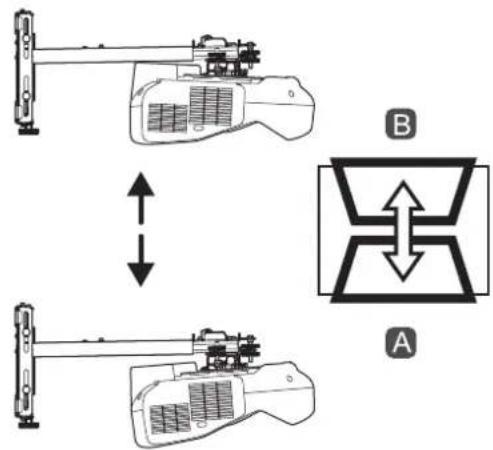
Use the adjustment dial on the top to adjust the vertical tilt 38
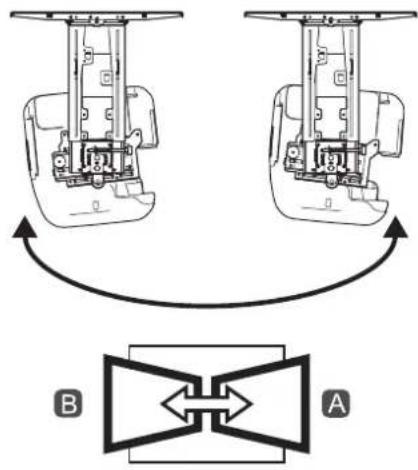
Adjust the horizontal slide 39
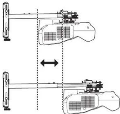
Adjust the forward/backward slide 39
Adjust the vertical slide 40
Re-adjust the focus 40
Turn off the display of the test pattern 41
7 Attaching the Covers 42
Attach the wall plate cover and end cap 42
Attach the cable cover to the projector 44
8 Appendix 45
Installing the Touch Unit and Control Pad 45
Using the Easy Interactive Function 45
Correcting the Image Shape on a Curved Screen 45
Attaching a Security Cable 46
Limited Warranty 47
Wall Mount
natural_image
Technical line drawing of a mechanical component with no visible text or symbolsWall mount

natural_image
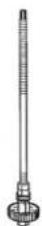
Technical line drawing of a rectangular electrical component with mounting flanges (no text or symbols)Wall plate

natural_image
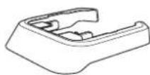
Two 3D mechanical parts shown in wireframe, no text or symbols presentWall plate cover

natural_image
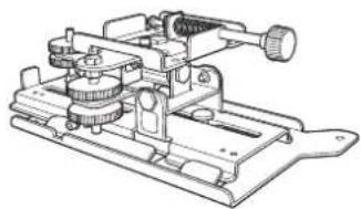
Technical line drawing of a mechanical clamp or fixture with gears and lever (no text or symbols)3-axis adjustment unit and slide plate (attached when shipped)
Hexagonal shaft
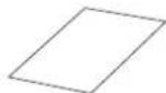
Template sheet (for installing the wall plate)
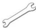
Open-ended wrench 13 mm (for M8 and M6) × 6 mm (for hexagonal shaft)
Masking sticker (for mount arm)
End cap
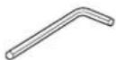
Hexagon wrench (for M4)
| Shape Name | Quantity Application | ||
 | M4 × 12 mm hexagon socket head cap bolt with washer/spring washer | 5 For wall plate assembly | |
| 4 For 3-axis adjustment unit/wall mount installation | |||
| 4 For slide plate/projector installation | |||
 | M6 × 20 mm hexagon shoulder bolt with washer/spring washer | 1 For wall mount/wall plate installation | |
 | M6 × 20 mm cross recessed head shoulder screw with plastic washer | 3 | |
- Use the bolts or screws supplied with the wall mount to install it as directed in this guide. Do not substitute these bolts with any other types.
- You need to use commercially available M10 × 60 mm anchors (at least 3) to attach the wall plate to the wall.
• Gather the tools and parts you need before you begin installation, including a #3 cross-head screwdriver.
| Item Specification | Additional information | Reference page | |
| Wall mount weight (including the 3-axis adjustment unit, slide plate, wall plate, wall plate cover, and end cap) | Approx. 15.9 lb (7.2 kg) | Wall mount: 6.4 lb (2.9 kg)3-axis adjustment unit: 2.2 lb (1.0 kg)Slide plate: 1.3 lb (0.6 kg)Wall plate: 4.4 lb (2.0 kg)Wall plate cover and end cap: 1.5 lb (0.7 kg) | — |
| Maximum load capacity 20.9 lb (9.5 kg) — — | |||
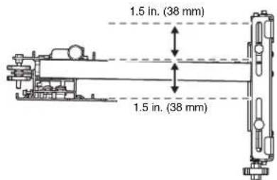
| Vertical slide adjustment range ±1.5 in. (38 mm) — Refer to the | illustration below | ||
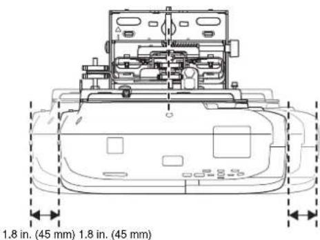
| Horizontal slide adjustment range ±1.8 in. (45 mm) — Refer to the | illustration on page 9 | ||
| Forward/backward slide adjustment range | 0.5 to 13.8 in.(13 to 350 mm) | Arm slide adjustment range: 0 to 10.4 in. (0 to 263 mm)Adjustment from 3-axis adjustment unit installation position: 3.4 in. (87 mm) | Refer to the illustration on page 9 |
| Horizontal roll adjustment range ±3° Fine adjustments possible with adjustment dial | p. 37 | ||
| Horizontal rotation adjustment range | ±8° Fine adjustments possible with adjustment knob | p. 38 | |
| Vertical tilt adjustment range ±3° Fine adjustments possible with adjustment dial | p. 38 | ||
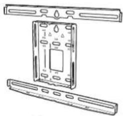
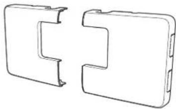
Wall plate
The wall plate is in three pieces when shipped. Use the included M4 × 12 mm bolts (×6) to attach the separate pieces together before mounting the projector. See page 25 for instructions.
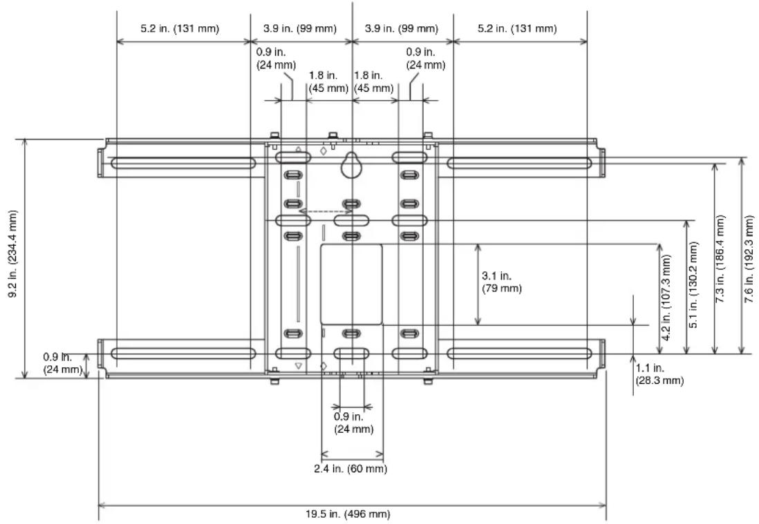
Vertical slide adjustment range
Horizontal slide adjustment range
Forward/backward slide adjustment range
Arm slide adjustment range
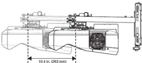
Adjustment from 3-axis adjustment unit installation position
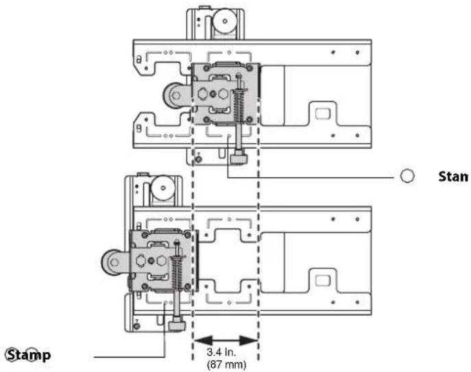
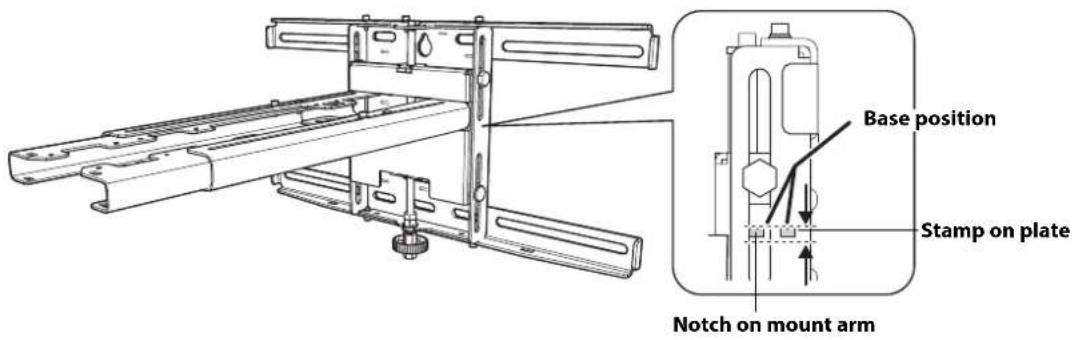
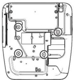
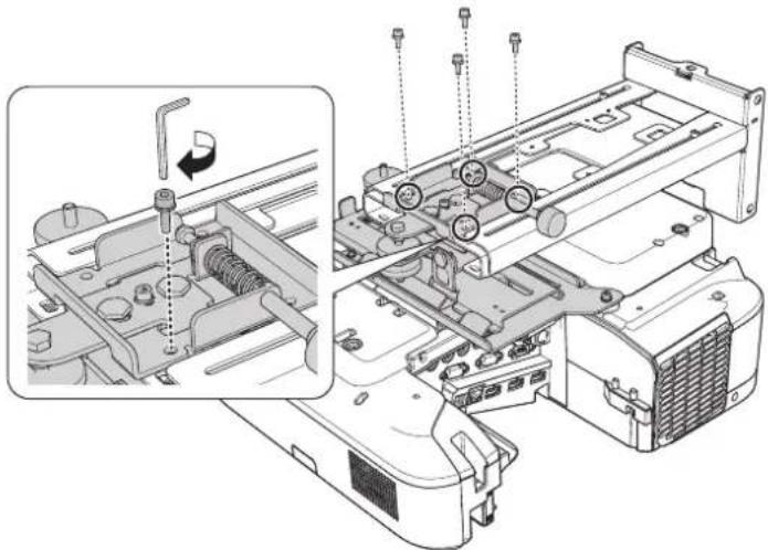
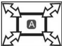
By changing the installation position of the 3-axis adjustment unit to the front or back, you can adjust the installation position of the projector.
When the screen size is less than 75 inches (85 inches for WUXGA images), install it at the position marked with a ③stamp on the mount arm.
When the screen size is 75 inches or more (85 inches or more for WUXGA images), install it at the position marked with a stamp on the mount arm.
To see these stamps, you need to remove the two top bolts and slide out the arm extension.
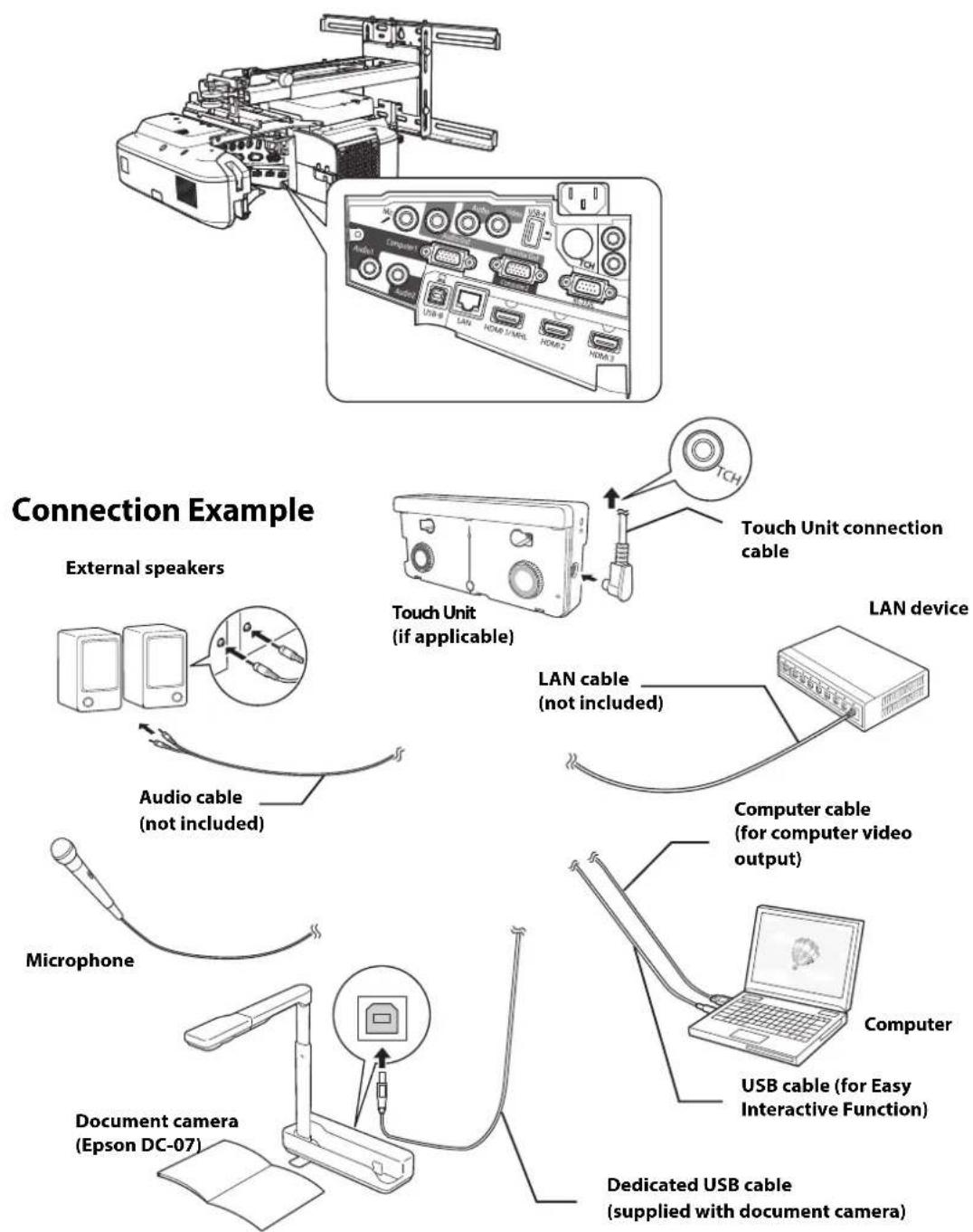
Make sure you have the power cord, computer cable, and other parts at the location where the wall mount is to be installed.
Make sure you also have all necessary cables for the Touch Unit (if applicable) and other devices, such as a document camera or microphone, that you will connect to the projector. Your projector's connection panel may differ slightly from the model in the illustrations. For details, refer to the online User's Guide for your projector.
flowchart
graph TD
    A["External speakers"] --> B["Audio cable (not included)"]
    B --> C["Microphone"]
    C --> D["Document camera (Epson DC-07)"]
    D --> E["Dedicated USB cable (supplied with document camera)"]
    E --> F["Computer"]
    F --> G["USB cable (for Easy Interactive Function)"]
    G --> H["Computer cable (for computer video output)"]
    H --> I["Laptop"]
    I --> J["LAN device"]
    J --> K["Touch Unit connection cable"]
    K --> L["TCH"]
    style A fill:#f9f,stroke:#333
    style B fill:#ccf,stroke:#333
    style C fill:#cfc,stroke:#333
    style D fill:#fcc,stroke:#333
    style E fill:#cff,stroke:#333
    style F fill:#ffc,stroke:#333
    style G fill:#fcc,stroke:#333
    style H fill:#ffc,stroke:#333
    style I fill:#fcc,stroke:#333
    style J fill:#ffc,stroke:#333
    style K fill:#cff,stroke:#333
    style L fill:#ffc,stroke:#333
For Interactive Use
When interacting with a computer, you need a USB cable. However, when using the projector's built-in toolbar, you do not need a USB cable.
Connecting the Control Pad
The Control Pad is included with the BrightLink Pro 1410Wi/1420Wi/1430Wi/1450Ui/1460Ui and BrightLink 697Ui projectors. It provides a convenient alternative to the remote control for turning on the projector and selecting whiteboard mode. Certain Control Pad models also have additional functions.
You must install the control pad on the same surface as the projector, within the range specified in the installation instructions. You can use the included batteries to power the control pad, or the optional remote control cable set (model ELPKC28, part number V12H005C28).

See the documentation included with your projector for details on mounting and connecting the Control Pad.
The BrightLink Pro 1410Wi/1420Wi/1430Wi, BrightLink 475W/485W/575Wi/575Wi+/585Wi/585Wi+/595Wi/595Wi+/675Wi+/685Wi/685Wi+/695Wi/695Wi+, and PowerLite 475W/485W/575W/585W/675W/685W can project a WXGA image up to 100 inches diagonally. The BrightLink Pro 1450Ui/1460Ui and BrightLink 696Ui/697Ui can project a WUXGA image up to 100 inches diagonally. The BrightLink 480i and PowerLite 470/480/570/580/680 can project an XGA image up to 93 inches diagonally.

This guide covers your projector's native resolution and aspect ratio. For other resolutions and aspect ratios, use the Throw Distance Calculator at www.epson.com/support (U.S.), www.epson.ca/support (Canada), or www.epson.com/jm/support (Latin America).
You can project onto a pre-installed whiteboard or directly onto a plain wall.
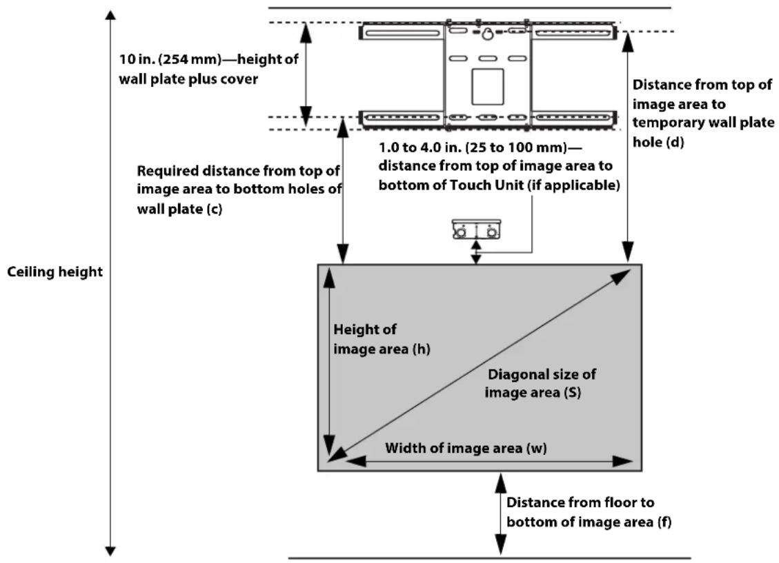
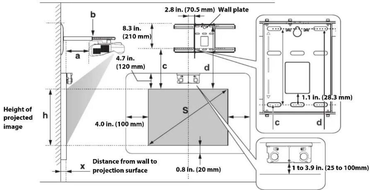
The height of the included wall mount determines the maximum image size and how high the image appears on the wall or whiteboard. The distance of the projector from the wall (once it is mounted on the adjustable arm of the wall mount) also affects image size and position.
When installing the Touch Unit (if applicable) on a whiteboard, you need at least 4.7 inches (120 mm) between the top edge of the projected image and the top edge of the projection surface. If you want to install the Touch Unit outside of the frame of a whiteboard, use the included Touch Unit Bracket. If the distance from the wall to the surface of the whiteboard is greater than 2 inches (51 mm) or the frame of the whiteboard extends more than 0.1 inch (3 mm) away from the board surface, you must install the Touch Unit on the whiteboard or screen.

See the documentation included with your projector for details on mounting the Touch Unit.
If you are planning to project on a whiteboard, the image may not fill the entire board, depending on the aspect ratio. If you match the image height to the board's height, gaps may appear on the sides of the board.
Use the following worksheets to determine the proper location of the wall plate on the wall. If you are projecting onto a pre-installed whiteboard, use the worksheet on page 14. If you are projecting on a plain wall, use the worksheet on page 15.

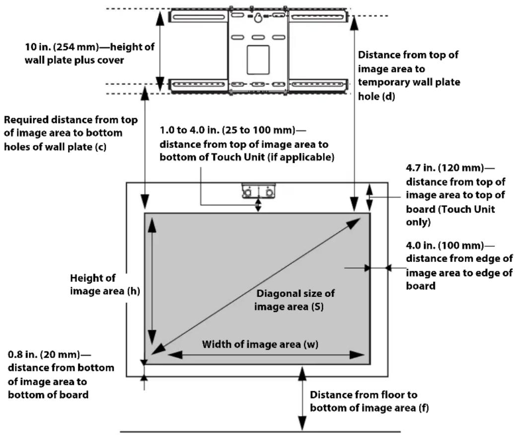
When installing the Touch Unit on a whiteboard (if applicable), make sure to leave the following gaps around the edge of the board:
☐ From the top of the projected image to the bottom of the Touch Unit: 1 to 4 inches (25 to 100 mm)
☐ From the edges of the projected image to the edges of the board: at least 4 inches (100 mm) left and right
☐ From the bottom of the projected image to the bottom of the board: 0.8 inch (20 mm)
If there are obstacles such as cables, whiteboard trays, pen holders, or frames within the areas listed above, the Touch Unit will not operate properly.
Installation worksheet for projecting on a pre-installed wall-mounted board

If you want to install the Touch Unit outside of the frame of a whiteboard, use the included Touch Unit Bracket. If the distance from the wall to the surface of the whiteboard is greater than 2 inches (51 mm) or the frame of the whiteboard extends more than 0.1 inch (3 mm) away from the board surface, you must install the Touch Unit on the whiteboard or screen.
See the documentation included with your projector for details on mounting the Touch Unit.
- Measure the ceiling height (distance from the floor to the ceiling). ____
- Measure the height of the board's image area (h). ____ (h)
- Measure the width of the board's image area (w). ____ (w)
- Measure the distance from the floor to the bottom of the board's image area (f). ____ (f)
- Measure the thickness of the board (distance from the projection surface to the wall) ____ (x) (x).
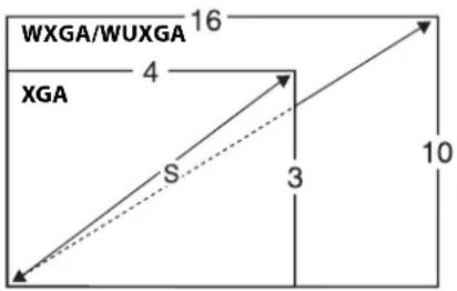
- Determine the aspect ratio of the board or of the images that will be projected. For new computers or laptops, this will most likely be WXGA or WUXGA (16:10). For older equipment, this will most likely be XGA (4:3). You may need to consult your IT department for this information.
4:3 XGA
16:10 WXGA/WUXGA
16:9 Widescreen
If your desired aspect ratio does not match the native aspect ratio of your product, use the Throw Distance Calculator at www.epson.com/support (U.S.), www.epson.ca/support (Canada), or www.epson.com.jm (Latin America) to determine the correct measurements.
- Using the tables on pages 19 to 23 and your desired image height (h), find the required distance between the top of the image area and the bottom holes of the wall plate (c). ____ (c)
- Using the tables on pages 19 to 23 and your desired image height (h), find the required distance between the top of the image area and the temporary wall plate hole (d). ____ (d)
- Determine the position for your projector installation by adding the values for (f), (h), and (c), plus an additional 10 inches for the height of the wall plate plus the cover. If the ceiling height of your room (as noted in step 1) does not meet the minimum ceiling height required for your board, you may need to select a smaller image size or move the board to a lower position on the wall. ____(f) ____(h) ____(c) +10 inches ____total
- After confirming your image size, use tape or a pencil to mark the distance (c) from the top of the image area on the board to the bottom holes of the wall plate.
- Align the line (horizontal) on the template sheet with the (c) mark, then align the center line on the template sheet with the center of the image area. Follow the instructions on page 25 to install the projector.
Installation worksheet for projecting on a plain wall
- Measure the ceiling height (distance from the floor to the ceiling). ____
- Determine the desired aspect ratio of the image. For new computers or laptops, this will most likely be WXGA or WUXGA (16:10). For older equipment, this will most likely be XGA (4:3). You may need to consult your IT department for this information.
4:3 XGA
16:10 WXGA/WUXGA
16:9 Widescreen
If your desired aspect ratio does not match the native resolution of your product, use the Throw Distance Calculator at www.epson.com/support (U.S.), www.epson.ca/support (Canada), or www.epson.com.jm (Latin America) to determine the correct measurements.
- Using the tables on pages 19 to 24, select the largest image size available for your ceiling height.
Image height (h) ____ (h)
Image width (w) ____ (w)
- Determine the desired distance from the floor to the bottom of the image area (f). ____ (f)
The recommended minimum distance is 30 inches (762 mm). Images appearing less than 28 inches (711 mm) from the floor may be obstructed for some viewers.
-
Find the top of the projected image area by adding distances (f) and (h).
-
Use the tables on pages 19 to 23 to determine the required distance from the top of the image area to the bottom holes of the wall plate (c). ____ (c)
-
Use the tables on pages 19 to 23 to determine the required distance between the top of the image area and the temporary wall plate hole (d). ____ (d)
-
Add:
Required distance from top of image area to bottom holes of wall plate (c) ____ (c)
Height of image area (h) ____ (h)
Distance from floor to bottom of image area (f) ____ (f)
Height of wall plate plus cover +10 inches
If the total exceeds the ceiling height, you will need to reduce the image size or reduce ____ total the distance from the floor to the bottom of the image area.
-
After confirming your image size, use tape or a pencil to mark the distance (c) from the top of the image area on the board to the bottom holes of the wall plate.
-
Align the line (horizontal) on the template sheet with the (c) mark, then align the center line on the template sheet with the center of the image area. Follow the instructions on page 25 to install the projector.
Projection distance worksheets
The tables on the following pages provide installation information for all native image sizes. The minimum ceiling height is based on an image 30 inches (762 mm) from the floor; if the image is lower, the minimum ceiling height is reduced by the corresponding measurement.
Use the worksheets, the illustrations, and the information in the tables on the following pages to determine the projection distance and placement of the wall plate.
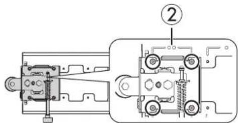
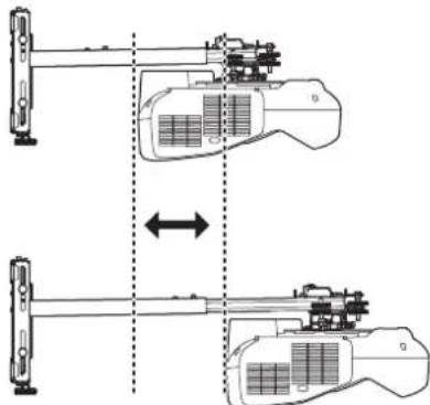
Diagonal image size and mounting position
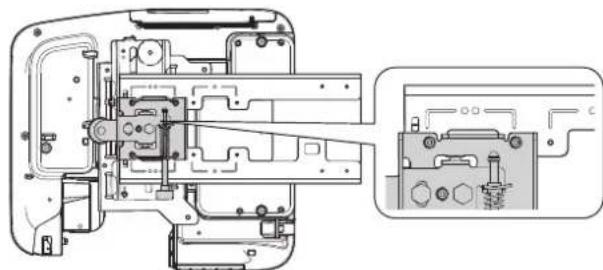
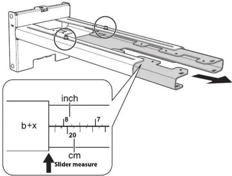
In order to see the stamp and the numbers on the slider scale, you need to slide out the arm extension.
When the diagonal image size is 75 inches or more (85 inches or more for WUXGA images), mount the 3-axis adjustment unit at the position marked with a Stamp.
natural_image
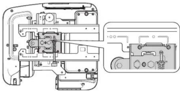
Technical line drawing of a mechanical assembly with internal components and a close-up inset (no text or symbols)When the diagonal image size is less than 75 inches (85 inches for WUXGA images), mount the 3-axis adjustment unit at the position marked with a stamp.
natural_image
Technical line drawing of a mechanical assembly with internal components and a close-up inset showing internal wiring (no text or symbols)Distance from projection surface to wall plate
The distance (c) from the projection surface to the bottom mounting holes on the wall plate is the number given when the vertical slide is set to the base position, as shown below.
Match the notch on the wall mount to the position of the stamp on the wall plate.
Installation measurement tables
Use the following table to determine which installation measurement table to use for your projector.

The measurements may differ depending on the location where you place the projector.
When projecting in Tele mode, the quality of the projected images may decrease.
| Projector model | Maximum image size (diagonal) | Installation measurement table |
| BrightLink Pro 1450Ui/1460Ui | 100 inches WUXGA | |
| BrightLink 696Ui/697Ui | ||
| BrightLink Pro 1410Wi/1420Wi/1430Wi | 100 inches WXGA | |
| BrightLink 475W/485W/575Wi/585Wi/595Wi/685Wi/695Wi | ||
| BrightLink 575Wi+/585Wi+/595Wi+/675Wi+/685Wi+/695Wi+ | ||
| PowerLite 475W/485W/575W/585W/675W/685W | ||
| BrightLink 480i | 93 inches XGA | |
| PowerLite 470/480/570/580/680 |

The throw distance measurements may differ slightly for the BrightLink Pro 1410Wi/1420Wi/1430Wi, BrightLink 475W/480i/485W/575Wi/575Wi+/585Wi/585Wi+/595Wi/595Wi+, and the PowerLite 470/475W/480/485W/570/575W/580/585W. For more information, see the Throw Distance Calculator at www.epson.com/support (U.S.), www.epson.ca/support (Canada), or www.epson.com/jm/support (Latin America).
Measurements in Inches for WXGA Projectors in Native Resolution
| Diagonal image size (S) | Min. ceiling height* | Image width (w) | Image height (h) | Min.projection distance (a) | Sliderscale mark (b) | Distance from top of image to bottom wall plate holes (c) | Distance from top of image to temporary wall plate hole (d) |
| 60" | 78.7 50.9 31.8 | 1.5 5.7 6.9 14 | 4 | ||||
| 61" | 79.3 51.7 32.3 | 1.7 5.9 7.0 14 | 6 | ||||
| 62" | 80.0 52.6 32.8 | 2.0 6.2 7.1 14 | 7 | ||||
| 63" | 80.6 53.4 33.4 | 2.2 6.4 7.2 14 | 8 | ||||
| 64" | 81.3 54.3 33.9 | 2.5 6.7 7.3 14 | 9 | ||||
| 65" | 81.9 55.1 34.4 | 2.7 6.9 7.4 15 | 0 | ||||
| 66" | 82.5 56.0 35.0 | 3.0 7.2 7.6 15 | 1 | ||||
| 67" | 83.2 56.8 35.5 | 3.2 7.4 7.7 15 | 2 | ||||
| 68" | 83.8 57.7 36.0 | 3.4 7.6 7.8 15 | 4 | ||||
| 69" | 84.4 58.5 36.6 | 3.7 7.9 7.9 15 | 4 | ||||
| 70" | 85.1 59.4 37.1 | 3.9 8.1 8.0 15 | 6 | ||||
| 71" | 85.7 60.2 37.6 | 4.2 8.4 8.1 15 | 7 | ||||
| 72" | 86.4 61.1 38.1 | 4.4 8.6 8.2 15 | 8 | ||||
| 73" | 87.0 61.9 38.7 | 4.6 8.9 8.3 15 | 9 | ||||
| 74" | 87.7 62.8 39.3 | 4.9 9.1 8.4 16 | 0 | ||||
| 75" | 88.3 63.6 39.8 | 5.2 5.9 8.5 16 | 1 | ||||
| 76" | 88.9 64.4 40.3 | 5.4 6.2 8.7 16 | 2 | ||||
| 77" | 89.6 65.3 40.8 | 5.6 6.4 8.8 16 | 3 | ||||
| 78" | 90.2 66.1 41.3 | 5.9 6.7 8.9 16 | 5 | ||||
| 79" | 90.9 67.0 41.9 | 6.1 6.9 9.0 16 | 5 | ||||
| 80" | 91.5 67.8 42.4 | 6.3 7.1 9.1 16 | 7 | ||||
| 81" | 92.1 68.7 42.9 | 6.6 7.4 9.2 16 | 8 | ||||
| 82" | 92.8 69.5 43.5 | 6.9 7.6 9.3 16 | 9 | ||||
| 83" | 93.4 70.4 44.0 | 7.1 7.9 9.4 17 | 0 | ||||
| 84" | 94.1 71.2 44.5 | 7.3 8.1 9.5 17 | 1 | ||||
| 85" | 94.7 72.1 45.1 | 7.6 8.3 9.6 17 | 2 | ||||
| 86" | 95.4 72.9 45.6 | 7.8 8.6 9.8 17 | 3 | ||||
| 87" | 96.0 73.8 46.1 | 8.1 8.9 9.9 17 | 4 | ||||
| 88" | 96.6 74.6 46.6 | 8.3 9.1 10.0 17 | 6 | ||||
| 89" | 97.3 75.5 47.2 | 8.5 9.3 10.1 17 | 6 | ||||
| 90" | 97.9 76.3 47.7 | 8.8 9.6 10.2 17 | 8 | ||||
| 91" | 98.5 77.2 48.2 | 9.0 9.8 10.3 17 | 9 | ||||
| 92" | 99.2 78.0 48.7 | 9.3 10.1 10.4 18 | 0 | ||||
| 93" | 99.8 78.9 49.3 | 9.5 10.3 10.6 18 | 1 | ||||
| 94" | 100.5 79.7 49.8 | 9.8 10.6 10.7 18 | 2 | ||||
| 95" | 101.1 80.6 50.4 | 10.0 10.8 10 | 7 18.3 | ||||
| 96" | 101.7 81.4 50.9 | 10.2 11.0 10 | 9 18.4 | ||||
| 97" | 102.4 82.2 51.4 | 10.5 11.3 11 | 0 18.5 | ||||
| 98" | 103.0 83.1 51.9 | 10.7 11.5 11 | 1 18.7 | ||||
| 99" | 103.7 83.9 52.4 | 11.0 11.8 11 | 2 18.8 | ||||
| 100" | 104.3 84.8 53.0 | 11.2 12.0 11 | 3 18.9 |
* Based on an image 30 inches from the floor; if the image is lower, the minimum ceiling height is reduced by the corresponding measurement.
Measurements in Inches for XGA Projectors in Native Resolution
| Diagonal image size (S) | Min. ceiling height* | Image width (w) | Image height (h) | Min. projection distance (a) | Sliderscale mark (b) | Distance from top of image to bottom wall plate holes (c) | Distance from top of image to temporary wall plate hole (d) |
| 60" | 82.4 48.0 36.0 | 2.7 6.9 6.4 14.0 | |||||
| 61" | 83.1 48.8 36.6 | 2.9 7.1 6.5 14.1 | |||||
| 62" | 83.8 49.6 37.2 | 3.2 7.4 6.6 14.2 | |||||
| 63" | 84.5 50.4 37.8 | 3.5 7.7 6.7 14.3 | |||||
| 64" | 85.2 51.2 38.4 | 3.7 7.9 6.8 14.4 | |||||
| 65" | 85.9 52.0 39.0 | 4.0 8.2 6.9 14.5 | |||||
| 66" | 86.6 52.8 39.6 | 4.2 8.4 7.0 14.6 | |||||
| 67" | 87.3 53.6 40.2 | 4.5 8.7 7.1 14.7 | |||||
| 68" | 88.0 54.4 40.8 | 4.8 9.0 7.2 14.8 | |||||
| 69" | 88.7 55.2 41.4 | 5.0 9.2 7.3 14.9 | |||||
| 70" | 89.4 56.0 42.0 | 5.3 9.5 7.4 15.0 | |||||
| 71" | 90.2 56.8 42.6 | 5.6 9.8 7.6 15.1 | |||||
| 72" | 90.9 57.6 43.2 | 5.8 10.0 7.6 15.2 | |||||
| 73" | 91.5 58.4 43.8 | 6.1 10.3 7.8 15.3 | |||||
| 74" | 92.2 59.2 44.4 | 6.3 10.5 7.8 15.4 | |||||
| 75" | 93.0 60.0 45.0 | 6.6 7.4 8.0 15.5 | |||||
| 76" | 93.7 60.8 45.6 | 6.9 7.6 8.1 15.6 | |||||
| 77" | 94.4 61.6 46.2 | 7.1 7.9 8.1 15.7 | |||||
| 78" | 95.1 62.4 46.8 | 7.4 8.1 8.3 15.8 | |||||
| 79" | 95.7 63.2 47.4 | 7.6 8.4 8.3 15.9 | |||||
| 80" | 96.5 64.0 48.0 | 7.9 8.7 8.5 16.0 | |||||
| 81" | 97.2 64.8 48.6 | 8.1 8.9 8.6 16.1 | |||||
| 82" | 97.9 65.6 49.2 | 8.4 9.2 8.7 16.2 | |||||
| 83" | 98.6 66.4 49.8 | 8.7 9.4 8.8 16.3 | |||||
| 84" | 99.3 67.2 50.4 | 8.9 9.7 8.9 16.4 | |||||
| 85" | 100.0 68.0 51.0 | 9.2 10.0 9.0 16.5 | |||||
| 86" | 100.7 68.8 51.6 | 9.4 10.2 9.1 16.7 | |||||
| 87" | 101.4 69.6 52.2 | 9.7 10.5 9.2 16.7 | |||||
| 88" | 102.1 70.4 52.8 | 10.0 10.7 9.3 16.9 | |||||
| 89" | 102.8 71.2 53.4 | 10.2 11.0 9.4 17.0 | |||||
| 90" | 103.5 72.0 54.0 | 10.5 11.3 9.5 17.0 | |||||
| 91" | 104.2 72.8 54.6 | 10.7 11.5 9.6 17.2 | |||||
| 92" | 104.9 73.6 55.2 | 11.0 11.8 9.7 17.2 | |||||
| 93" | 105.6 74.4 55.8 | 11.3 12.0 9.8 17.4 | |||||
| 94" | 106.3 75.2 56.4 | 11.5 12.3 9.9 17.5 |
* Based on an image 30 inches from the floor; if the image is lower, the minimum ceiling height is reduced by the corresponding measurement.
Measurements in Inches for WUXGA Projectors in Native Resolution
| Diagonal image size (S) | Min. ceiling height* | Image width (w) | Image height (h) | Min. projection distance (a) | Sliderscale mark (b) | Distance from top of image to bottom wall plate holes (c) | Distance from top of image to temporary wall plate hole (d) |
| 70" | 85.5 59.4 37.1 | 2.2 6.5 8.4 16.0 | |||||
| 71" | 86.2 60.2 37.6 | 2.4 6.7 8.5 16.1 | |||||
| 72" | 86.8 61.1 38.1 | 2.7 7.0 8.7 16.2 | |||||
| 73" | 87.5 61.9 38.7 | 2.9 7.2 8.8 16.3 | |||||
| 74" | 88.1 62.8 39.2 | 3.2 7.5 8.9 16.5 | |||||
| 75" | 88.7 63.6 39.8 | 3.4 7.7 9.0 16.5 | |||||
| 76" | 89.4 64.4 40.3 | 3.7 8.0 9.1 16.7 | |||||
| 77" | 90.0 65.3 40.8 | 3.9 8.2 9.2 16.8 | |||||
| 78" | 90.7 66.1 41.3 | 4.2 8.5 9.3 16.9 | |||||
| 79" | 91.3 67.0 41.9 | 4.4 8.7 9.4 17.0 | |||||
| 80" | 91.9 67.8 42.4 | 4.6 8.9 9.5 17.1 | |||||
| 81" | 92.6 68.7 42.9 | 4.9 9.2 9.6 17.2 | |||||
| 82" | 93.2 69.5 43.5 | 5.2 9.4 9.8 17.3 | |||||
| 83" | 93.9 70.4 44.0 | 5.4 9.7 9.9 17.4 | |||||
| 84" | 94.5 71.2 44.5 | 5.7 9.9 10.0 17.6 | |||||
| 85" | 95.1 72.1 45.0 | 5.9 6.8 10.1 17.6 | |||||
| 86" | 95.8 72.9 45.6 | 6.1 7.0 10.2 17.8 | |||||
| 87" | 96.4 73.8 46.1 | 6.4 7.2 10.3 17.9 | |||||
| 88" | 97.1 74.6 46.7 | 6.7 7.5 10.4 18.0 | |||||
| 89" | 97.7 75.5 47.2 | 6.9 7.8 10.6 18.1 | |||||
| 90" | 98.4 76.3 47.7 | 7.1 8.0 10.7 18.2 | |||||
| 91" | 99.0 77.2 48.2 | 7.4 8.2 10.7 18.3 | |||||
| 92" | 99.6 78.0 48.8 | 7.6 8.5 10.9 18.4 | |||||
| 93" | 100.3 78.9 49.3 | 7.9 8.7 11.0 18.5 | |||||
| 94" | 100.9 79.7 49.8 | 8.1 9.0 11.1 18.7 | |||||
| 95" | 101.6 80.6 50.4 | 8.4 9.3 11.2 18.8 | |||||
| 96" | 102.2 81.4 50.9 | 8.6 9.5 11.3 18.9 | |||||
| 97" | 102.8 82.2 51.4 | 8.9 9.7 11.4 19.0 | |||||
| 98" | 103.5 83.1 51.9 | 9.1 10.0 11.5 19.1 | |||||
| 99" | 104.1 83.9 52.5 | 9.4 10.2 11.7 19.2 | |||||
| 100" | 104.3 84.8 53 | 9.6 10.5 11.8 19.3 |
* Based on an image 30 inches from the floor; if the image is lower, the minimum ceiling height is reduced by the corresponding measurement.
Measurements in Centimeters for WXGA Projectors in Native Resolution
| Diagonal image size (S) | Min. ceiling height* | Image width (w) | Image height (h) | Min. projection distance (a) | Sliderscale mark (b) | Distance from top of image to bottom wall plate holes (c) | Distance from top of image to temporary wall plate hole (d) |
| 60" | 199.9 129.2 80 | 8.3 8 14.5 17 | 5 36.7 | ||||
| 61" | 201.5 131.4 82 | 1 4.4 15.1 17 | 8 37.0 | ||||
| 62" | 203.1 133.5 83 | 4 5.0 15.7 18 | 1 37.3 | ||||
| 63" | 204.8 135.7 84 | 8 5.6 16.3 18 | 4 37.6 | ||||
| 64" | 206.4 137.9 86 | 2 6.3 17.0 18 | 6 37.8 | ||||
| 65" | 208.0 140.0 87 | 5 6.9 17.6 18 | 9 38.1 | ||||
| 66" | 209.6 142.2 88 | 8 7.5 18.2 19 | 2 38.4 | ||||
| 67" | 211.3 144.3 90 | 2 8.1 18.8 19 | 5 38.7 | ||||
| 68" | 212.9 146.5 91 | 5 8.7 19.4 19 | 8 39.0 | ||||
| 69" | 214.5 148.6 92 | 9 9.3 20.0 20 | 0 39.2 | ||||
| 70" | 216.2 150.8 94 | 3 10.0 20.7 20 | 0.3 39.5 | ||||
| 71" | 217.8 152.9 95 | 6 10.6 21.3 20 | 0.6 39.8 | ||||
| 72" | 219.4 155.1 96 | 9 11.2 21.9 20 | 0.9 40.1 | ||||
| 73" | 221.0 157.2 98 | 2 11.8 22.5 20 | 1.2 40.4 | ||||
| 74" | 222.7 159.4 99 | 7 12.4 23.1 20 | 1.4 40.6 | ||||
| 75" | 224.3 161.5 10 | 1.0 13.1 15.1 | 21.7 40.9 | ||||
| 76" | 225.9 163.7 10 | 2.3 13.7 15.7 | 22.0 41.2 | ||||
| 77" | 227.5 165.9 10 | 3.6 14.3 16.3 | 22.3 41.5 | ||||
| 78" | 229.2 168.0 10 | 5.0 14.9 16.9 | 22.6 41.8 | ||||
| 79" | 230.8 170.2 10 | 6.4 15.5 17.5 | 22.8 42.0 | ||||
| 80" | 232.4 172.3 10 | 7.7 16.1 18.1 | 23.1 42.3 | ||||
| 81" | 234.0 174.5 10 | 9.0 16.8 18.8 | 23.4 42.6 | ||||
| 82" | 235.7 176.6 11 | 0.4 17.4 19.4 | 23.7 42.9 | ||||
| 83" | 237.3 178.8 11 | 1.7 18.0 20.0 | 24.0 43.2 | ||||
| 84" | 238.9 180.9 11 | 3.1 18.6 20.6 | 24.2 43.4 | ||||
| 85" | 240.6 183.1 11 | 4.5 19.2 21.2 | 24.5 43.7 | ||||
| 86" | 242.2 185.2 11 | 5.8 19.9 21.9 | 24.8 44.0 | ||||
| 87" | 243.8 187.4 11 | 7.1 20.5 22.5 | 25.1 44.3 | ||||
| 88" | 245.4 189.5 11 | 8.4 21.1 23.1 | 25.4 44.6 | ||||
| 89" | 247.1 191.7 11 | 9.9 21.7 23.7 | 25.6 44.8 | ||||
| 90" | 248.7 193.9 12 | 1.2 22.3 24.3 | 25.9 45.1 | ||||
| 91" | 250.3 196.0 12 | 2.5 22.9 24.9 | 26.2 45.4 | ||||
| 92" | 251.9 198.2 12 | 3.8 23.6 25.6 | 26.5 45.7 | ||||
| 93" | 253.6 200.3 12 | 5.2 24.2 26.2 | 26.8 46.0 | ||||
| 94" | 255.2 202.5 12 | 6.5 24.8 26.8 | 27.1 46.3 | ||||
| 95" | 256.8 204.6 12 | 7.9 25.4 27.4 | 27.3 46.5 | ||||
| 96" | 258.4 206.8 12 | 9.2 26.0 28.0 | 27.6 46.8 | ||||
| 97" | 260.1 208.9 13 | 0.6 26.7 28.7 | 27.9 47.1 | ||||
| 98" | 261.7 211.1 13 | 1.9 27.3 29.3 | 28.2 47.4 | ||||
| 99" | 263.3 213.2 13 | 3.2 27.9 29.9 | 28.5 47.7 | ||||
| 100" | 265.0 215.3 13 | 4.7 28.5 30.5 | 28.7 47.9 |
* Based on an image 76.2 cm from the floor; if the image is lower, the minimum ceiling height is reduced by the corresponding measurement.
Measurements in Centimeters for XGA Projectors in Native Resolution
| Diagonal image size (S) | Min. ceiling height* | Image width (w) | Image height (h) | Min. projection distance (a) | Sliderscale mark (b) | Distance from top of image to bottom wall plate holes (c) | Distance from top of image to temporary wall plate hole (d) |
| 60" | 209.3 121.9 91 | 4.6.8 17.5 16 | 3.35.5 | ||||
| 61" | 211.1 124.0 92 | 9.7.4 18.1 16 | 6.35.8 | ||||
| 62" | 212.9 126.0 94 | 5.8.1 18.8 16 | 8.36.0 | ||||
| 63" | 214.7 128.0 96 | 0.8.8 19.5 17 | 1.36.3 | ||||
| 64" | 216.5 130.0 97 | 6.9.4 20.1 17 | 3.36.5 | ||||
| 65" | 218.3 132.1 99 | 1.10.1 20.8 1 | 7.636.8 | ||||
| 66" | 220.0 134.1 10 | 0.5 10.7 21.4 | 17.937.1 | ||||
| 67" | 221.8 136.1 10 | 2.1 11.4 22.1 | 18.137.3 | ||||
| 68" | 223.6 138.2 10 | 3.6 12.1 22.8 | 18.437.6 | ||||
| 69" | 225.4 140.2 10 | 5.2 12.7 23.4 | 18.637.8 | ||||
| 70" | 227.2 142.2 10 | 6.7 13.4 24.1 | 18.938.1 | ||||
| 71" | 229.0 144.3 10 | 8.2 14.1 24.8 | 19.238.4 | ||||
| 72" | 230.8 146.3 10 | 9.8 14.7 25.4 | 19.438.6 | ||||
| 73" | 232.5 148.3 11 | 1.2 15.4 26.1 | 19.738.9 | ||||
| 74" | 234.3 150.4 11 | 2.8 16.0 26.7 | 19.939.1 | ||||
| 75" | 236.1 152.4 11 | 4.3 16.7 18.7 | 20.239.4 | ||||
| 76" | 237.9 154.4 11 | 5.8 17.4 19.4 | 20.539.7 | ||||
| 77" | 239.7 156.5 11 | 7.4 18.0 20.0 | 20.739.9 | ||||
| 78" | 241.5 158.5 11 | 8.9 18.7 20.7 | 21.040.2 | ||||
| 79" | 243.2 160.5 12 | 0.4 19.4 21.4 | 21.240.4 | ||||
| 80" | 245.0 162.6 12 | 1.9 20.0 22.0 | 21.540.7 | ||||
| 81" | 246.8 164.6 12 | 3.4 20.7 22.7 | 21.841.0 | ||||
| 82" | 248.6 166.6 12 | 5.0 21.3 23.3 | 22.041.2 | ||||
| 83" | 250.4 168.7 12 | 6.5 22.0 24.0 | 22.341.5 | ||||
| 84" | 252.2 170.7 12 | 8.1 22.7 24.7 | 22.541.7 | ||||
| 85" | 253.9 172.7 12 | 9.5 23.3 25.3 | 22.842.0 | ||||
| 86" | 255.7 174.8 13 | 1.0 24.0 26.0 | 23.142.3 | ||||
| 87" | 257.5 176.8 13 | 2.6 24.7 26.7 | 23.342.5 | ||||
| 88" | 259.3 178.8 13 | 4.1 25.3 27.3 | 23.642.8 | ||||
| 89" | 261.1 180.8 13 | 5.6 26.0 28.0 | 23.943.1 | ||||
| 90" | 262.9 182.9 13 | 7.2 26.6 28.6 | 24.143.3 | ||||
| 91" | 264.7 184.9 13 | 8.7 27.3 29.3 | 24.443.6 | ||||
| 92" | 266.4 186.9 14 | 0.2 28.0 30.0 | 24.643.8 | ||||
| 93" | 268.2 189.0 14 | 1.7 28.6 30.6 | 24.944.1 | ||||
| 94" | 270.0 191.0 14 | 3.2 29.3 31.3 | 25.244.4 |
* Based on an image 76.2 cm from the floor; if the image is lower, the minimum ceiling height is reduced by the corresponding measurement.
Measurements in Centimeters for WUXGA Projectors in Native Resolution
| Diagonal image size (S) | Min. ceiling height* | Image width (w) | Image height (h) | Min. projection distance (a) | Sliderscale mark (b) | Distance from top of image to bottom wall plate holes (c) | Distance from top of image to temporary wall plate hole (d) |
| 70" | 217.2 150.8 94 | 2.5 6 16.5 21 | 4 40.6 | ||||
| 71" | 218.9 152.9 95 | 6 6.2 17.1 21 | 7 40.9 | ||||
| 72" | 220.5 155.1 96 | 9 6.8 17.7 22 | 0 41.2 | ||||
| 73" | 222.2 157.2 98 | 3 7.4 18.3 22 | 3 41.5 | ||||
| 74" | 223.8 159.4 99 | 6 8.1 19.0 22 | 6 41.8 | ||||
| 75" | 225.4 161.5 10 | 1.0 8.7 19.6 2 | 2.8 42.0 | ||||
| 76" | 227.0 163.7 10 | 2.3 9.3 20.2 2 | 3.1 42.3 | ||||
| 77" | 228.7 165.9 10 | 3.7 10.0 20.9 | 23.4 42.6 | ||||
| 78" | 230.3 168.0 10 | 5.0 10.6 21.5 | 23.7 42.9 | ||||
| 79" | 231.9 170.2 10 | 6.3 11.2 22.1 | 24.0 43.2 | ||||
| 80" | 233.5 172.3 10 | 7.7 11.8 22.7 | 24.2 43.4 | ||||
| 81" | 235.1 174.5 10 | 9.0 12.5 23.4 | 24.5 43.7 | ||||
| 82" | 236.8 176.6 11 | 0.4 13.1 24.0 | 24.8 44.0 | ||||
| 83" | 238.4 178.8 11 | 1.7 13.7 24.6 | 25.1 44.3 | ||||
| 84" | 240.1 180.9 11 | 3.1 14.4 25.2 | 25.4 44.6 | ||||
| 85" | 241.6 183.1 11 | 4.4 15.0 17.2 | 25.6 44.8 | ||||
| 86" | 243.3 185.2 11 | 5.8 15.6 17.8 | 25.9 45.1 | ||||
| 87" | 244.9 187.4 11 | 7.1 16.2 18.4 | 26.2 45.4 | ||||
| 88" | 246.6 189.5 11 | 8.5 16.9 19.1 | 26.5 45.7 | ||||
| 89" | 248.2 191.7 11 | 9.8 17.5 19.7 | 26.8 46.0 | ||||
| 90" | 249.9 193.9 12 | 1.2 18.1 20.3 | 27.1 46.3 | ||||
| 91" | 251.4 196.0 12 | 2.5 18.7 20.9 | 27.3 46.5 | ||||
| 92" | 253.1 198.2 12 | 3.9 19.4 21.6 | 27.6 46.8 | ||||
| 93" | 254.7 200.3 12 | 5.2 20.0 22.2 | 27.9 47.1 | ||||
| 94" | 256.3 202.5 12 | 6.5 20.6 22.8 | 28.2 47.4 | ||||
| 95" | 258.0 204.6 12 | 7.9 21.3 23.5 | 28.5 47.7 | ||||
| 96" | 259.5 206.8 12 | 9.2 21.9 24.1 | 28.7 47.9 | ||||
| 97" | 261.2 208.9 13 | 0.6 22.5 24.7 | 29.0 48.2 | ||||
| 98" | 262.8 211.1 13 | 1.9 23.1 25.3 | 29.3 48.5 | ||||
| 99" | 264.5 213.2 13 | 3.3 23.8 26.0 | 29.6 48.8 | ||||
| 100" | 266.1 215.4 13 | 4.6 24.4 26.6 | 29.9 49.1 |
* Based on an image 76.2 cm from the floor; if the image is lower, the minimum ceiling height is reduced by the corresponding measurement.
Make sure to follow the steps below to install the wall mount. If you ignore these steps, the wall mount could fall and cause personal injury or property damage.

Warning
☐ When you mount the projector on the wall with the wall mount, the wall requires enough strength to hold the projector and the wall mount, as well as the Control Pad and the Touch Unit, if applicable.
This wall mount should be installed on a concrete wall. Confirm the weight of the projector and the wall mount before installation, and maintain the strength of the wall. If the wall is not strong enough, reinforce the wall before installation.
☐ The maximum combined weight of the projector and the wall mount is 36.8 lb (16.7 kg).
☐Do not hang cable over the wall mount.
☐ Install the wall mount so that it can sufficiently support the weight of the projector and wall mount, and resist any horizontal vibration. Use M10 nuts and bolts and make sure to use appropriate wall anchors for your wall type. Nuts and bolts smaller than M10 could cause the wall mount to fall.
☐ Epson accepts no responsibility for any damage or injury caused by lack of wall strength or inadequate installation.

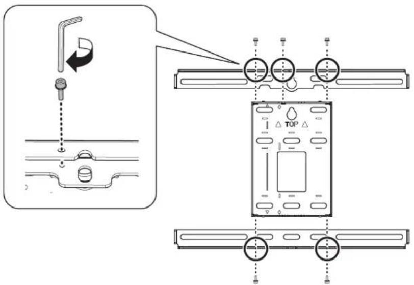
Assemble the parts
1. Assemble the wall plate.
Assemble the wall plate and two frames into one unit, and secure them with the M4 × 12 mm hexagon socket head cap bolts (×5) supplied.
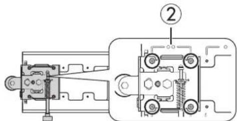
- Align the 3-axis adjustment unit with the slide plate's alignment mark.
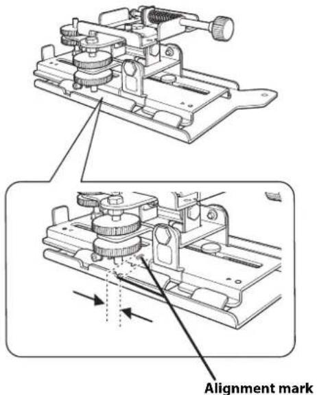
If the 3-axis adjustment unit is not aligned, loosen the M4 x 12 mm hexagon socket head cap bolt (①) and correct the alignment (②) then, tighten the M4 x 12 mm hexagon socket head cap bolt.
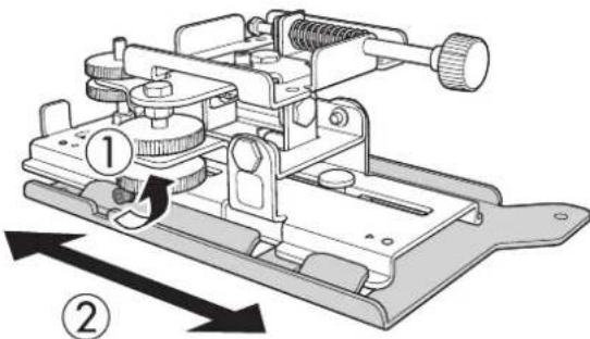
- Attach the 3-axis adjustment unit and slide plate to the projector.
Attach the 3-axis adjustment unit and slide plate to the projector using the M4 × 12 mm hexagon socket head cap bolts (×4) supplied.
natural_image
Technical line drawing of a mechanical assembly with gears and shafts (no text or symbols)Bolt locations
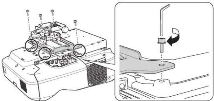
natural_image
Technical diagram of a mechanical device with internal components and a close-up view showing a screw being inserted (no text or labels present)
Install the wall plate on the wall
-
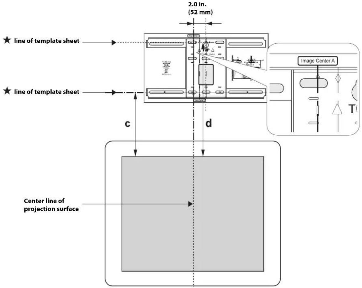
Determine the template sheet position.
-
From the projection distance table, confirm the screen size (S), the distance between the projection image and wall plate bottom holes (c), and the distance between the projection image and temporary wall plate hole (d).
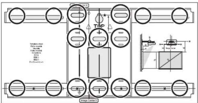
- For the BrightLink 475Wi/480i/485Wi/575Wi/575Wi+/585Wi/585Wi+/595Wi/595Wi+/675Wi+/685Wi/685Wi+/695Wi/695Wi+, BrightLink Pro 1410Wi/1420Wi/1430Wi, and PowerLite 470/475W/480/485W/570/575W/580/585W/675W/680/685W, align the Image Center A line (vertical) of the template sheet with the center line (vertical) of the projection surface.
For the BrightLink 696Ui/697Ui and BrightLink Pro 1450Ui/1460Ui, align the Image Center B line (vertical) of the template sheet with the center line (vertical) of the projection surface.
Confirm where the beams or studs are within the wall, and shift the position of the template left or right as necessary.
The position can be shifted horizontally left or right from the center line of the projection surface up to a maximum of 1.77 inches (45 mm.)
- Align the lines (horizontal) on the template with the height of (c) and (d).

If you want to hide the projector power plug under the wall plate cover, make sure the power outlet is located in the empty space to the left or the right of the wall plate and is between 3.7 inches (93.5 mm) and 4.9 inches (123.5 mm) from the center of the wall plate (not the center of the projection surface). If the outlet is more than 4.9 inches (123.5 mm) from the center of the wall plate, the power plug will not fit under the cover.
- Attach the template sheet to the wall.
- Drive an M10 screw (not included) into the temporary wall plate hole. Leave at least 0.2 inch (6 mm) between the screw head and the wall.
- Determine the position of the wall plate's mounting holes. Use at least four mounting holes.
Steps 5 to 9 below provide instructions for attaching the wall plate to a concrete wall.
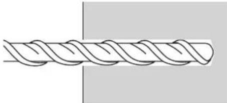
- Drill holes of the following diameters and depths.
| Drill diameter 0.41 in. (10.5 mm) | |
| Pilot hole depth 1.8 in. (45 mm) | |
| Anchor hole depth 1.6 in. (40 mm) |
natural_image
Pure line drawing of a twisted rope or helix without any text, numbers, or symbols- Remove the template sheet.
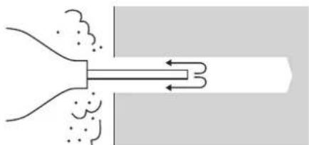
- Use a device such as a dust pump to clean out concrete dust from the hole.
natural_image
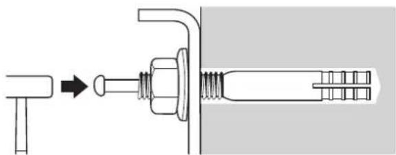
Diagram of a funnel emitting particles into a pipe with directional arrows (no text or labels)- Position the wall plate on the wall and insert M10 × 60 mm expansion anchors into the holes. Attach the nut and tap it with a hammer until the core touches the top of the anchor.
natural_image
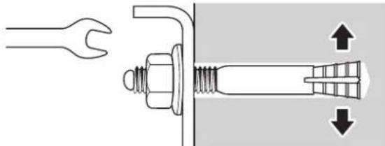
Diagram showing a mechanical assembly with a bolt and threaded component, no text or symbols present- Tighten the nut with a wrench to secure the wall plate to the wall.
natural_image
Technical diagram showing a wrench inserted into a bolt, with directional arrows indicating movement or force (no text or symbols present)- Remove the temporary wall plate screw.

Determine the projection distance and pull out the mount arm slider
-
Using the tables on pages 19 to 24, check the number for the slider measure (b).
-
Loosen the M4 × 12 mm hexagon socket head cap bolts (×2), and then pull out the slider on the wall mount.
Align the slider with the measure (b+x) that is equal to the slider measure (b) plus the thickness of the projection screen (x).
For an illustration of how to measure the thickness of the projection screen (x), see page 17.
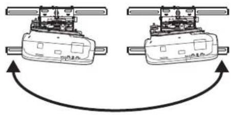
Route the cables through the wall mount arm


BrightLink 595Wi/695Wi/595Wi+/695Wi+/696Ui/697Ui and
BrightLink Pro 1430Wi/1450Ui/1460Ui: Make sure to route the Touch Unit connection cable through the wall mount arm. Route the Touch Unit connection cable so that the end that connects to the Touch Unit appears from the lower part of the wall mount as shown above.
⑤ Attach the mount arm to the wall plate
- Insert the hexagonal shaft into the wall mount ().①
- Insert and turn the hexagonal shaft at the top of the mount arm into the slot on the wall plate (②).
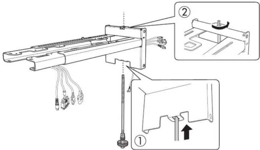
- Insert the hexagonal shaft into the slot at the top of the wall plate ( ).①
- Insert the hexagonal shaft into the slot at the bottom of the wall plate (②).
Caution
☐ Make sure the Touch Unit connection cable is not wired into the wall with the other cables.
☐Take care not to trap the cables between the mount arm and wall plate.
- Secure the mount arm to the wall plate by tightening the supplied M6 × 20 mm cross recessed head shoulder screws (×3) with the #3 cross-head screwdriver (①). Then, loosely tighten the M6 × 20 mm hexagon shoulder bolt supplied (②)

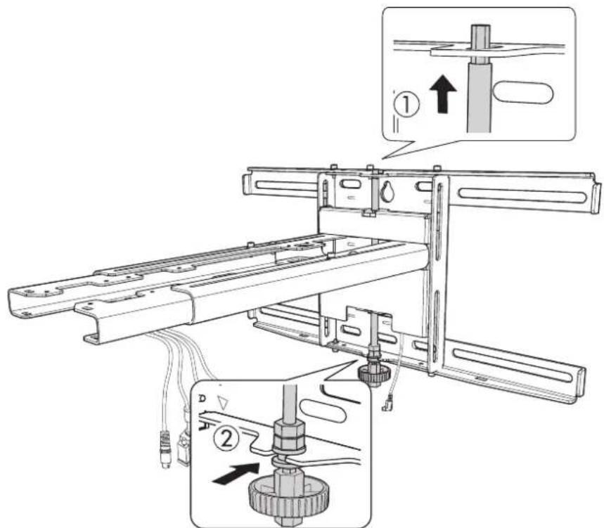
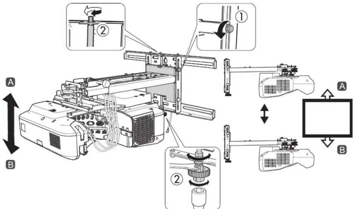
Adjust the vertical slide position of the arm
- Adjust the vertical slide with the M8 hexagon bolt at the bottom of the wall mount (②), or the hexagonal shaft at the top of the wall mount (①). Start by aligning the notch on the arm with the alignment mark on the wall plate as shown below.
Tightening the M8 hexagon bolt lowers the wall mount, and loosening the bolt raises it (②)
Tightening the hexagonal shaft raises the wall mount, and loosening the shaft lowers it (1).
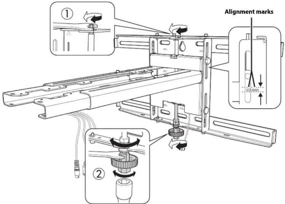
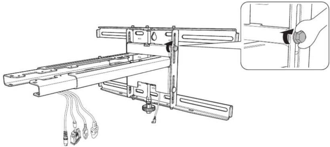
- Tighten the M6 × 20 mm hexagon shoulder bolt to secure the wall mount.
natural_image
Technical line drawing of a mechanical assembly with attached wires and a close-up inset showing a hand holding a cylindrical component (no text or symbols present)
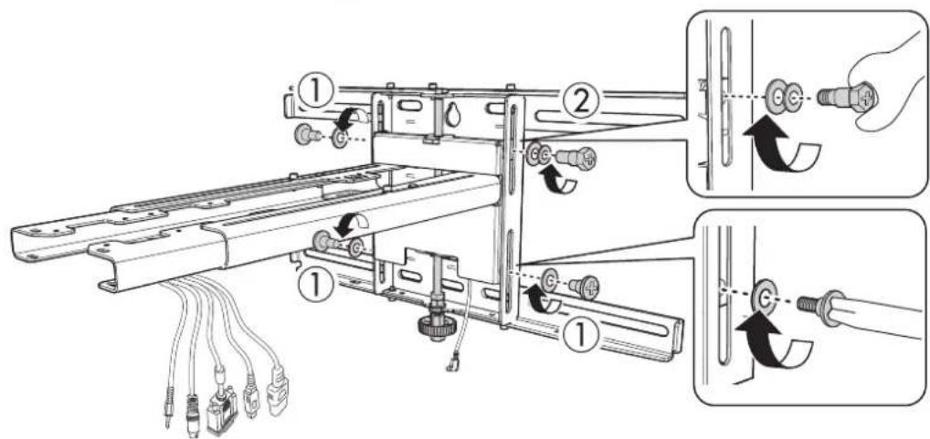
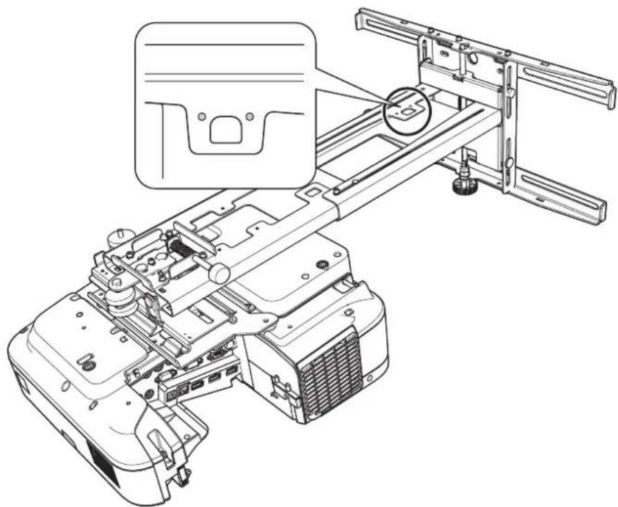
Attach the projector to the wall mount
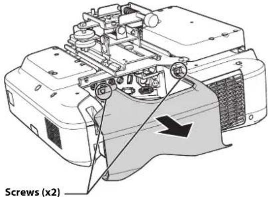
- Loosen the two screws with a cross-head screwdriver and remove the cable cover from the projector.
- Attach the 3-axis adjustment unit to the wall mount arm.
- Decide which position you want to use for installing the 3-axis adjustment unit.
Mount it at the ○ stamp (①) when the image is less than 75 inches diagonally (85 inches for WUXGA images), or at the stamp () when the projected image is 75 inches or more diagonally (85 inches or more for WUXGA images).
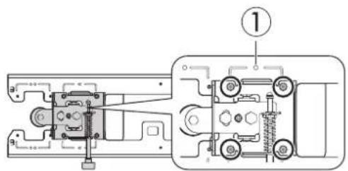
- Tighten the M4 × 12 mm hexagon socket head cap bolts (×4) supplied to install the 3-axis adjustment unit.
natural_image
Technical diagram of a mechanical assembly with exploded view and close-up detail (no text or symbols)
Warning
When installing or adjusting the wall mount, do not use adhesives to prevent the screws from loosening and do not use lubricants or oils on the projector slide plate. This may cause the case to crack and the projector to fall, resulting in personal injury or property damage.

Connect the power cord and other cables to the projector
Connect any necessary cables such as the computer cable, HDMI cable, USB cable, Touch Unit connection cable (if applicable), Control Pad cables (if applicable), and power cord to the projector. See your projector's User Guide for detailed connection information.
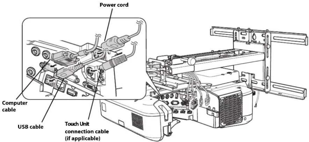
Use M4 screws (not included) to secure any additional devices or accessories, such as external tuners, to the mounting point on the wall mount.
natural_image
Technical line drawing of a mechanical assembly with no visible text or symbolsIf you are planning to run the cables inside the wall, make sure you follow all local electrical codes. If you are running the cables outside the wall, use a cable management system to keep the cables from obstructing the image. An optional cable management system is available from Epson (part number ELPCK01).
To ensure the best image quality, follow the steps below to adjust the projected image.

Do not make adjustments with the Quick Corner or Keystone functions of the projector. Doing so may result in a reduction in image quality and pen or finger touch calibration.
Follow these guidelines for setting up the projector:
- Make sure the image is evenly rectangular, without distortion.
- Make sure the projector is tilted no more than 3^ vertically and horizontally in relation to the projected image.

Your remote control or projector control panel may look different from the illustrations in this section, but the instructions are the same except where noted.
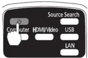
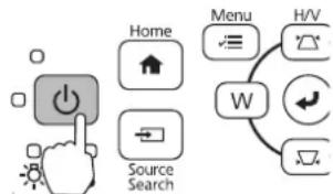
①Turn on the projector
Remote Control Control Panel
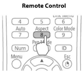
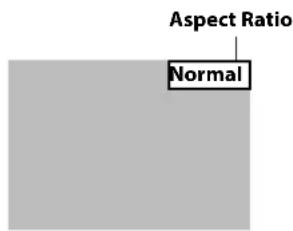
② Change the aspect ratio if necessary
Each time you press the [Aspect] button on the remote control, the aspect name is displayed on the screen and the aspect ratio changes. You will need to re-display the test pattern after changing the aspect ratio.
Change the setting according to the signal for the connected equipment.

You will need to project content from a connected device in order to change the aspect ratio.
Alternatively, set the aspect ratio from the Signal menu - Aspect. Following is a list of available aspect settings:
BrightLink 480i and PowerLite 470/480/570/580/680
- Auto: Automatically sets the aspect ratio according to the input signal and the Resolution setting (available only for HDMI image sources).
- Normal: Displays images using the full projection area and maintains the aspect ratio of the image. Choose this setting or Auto to automatically resize the image and make the best use of the display area.
- 4:3: Displays images using the full projection area at 4:3 aspect ratio.
- 16:9: Converts the aspect ratio of the image to 16:9. 4:3 ratio images are elongated horizontally to fit.
BrightLink Pro 1410Wi/1420Wi/1430Wi/1450Ui/1460Ui, BrightLink 475Wi/485Wi/575Wi/575Wi+/585Wi/585Wi+/595Wi/595Wi+/675Wi+/685Wi/685Wi+/695Wi/695Wi+/696Ui/697Ui, and PowerLite 475W/485W/575W/585W/675W/685W
- Auto: Automatically sets the aspect ratio according to the input signal and the Resolution setting (available only for HDMI image sources).
- Normal: Displays images using the full projection area and maintains the aspect ratio of the image. Choose this setting or Auto to automatically resize the image and make the best use of the display area.
- 16:9: Converts the aspect ratio of the image to 16:9. 4:3 ratio images are elongated horizontally to fit.
- Full: Displays images using the full width of the projection area, but does not retain the aspect ratio. 4:3 ratio images are elongated horizontally.
- Zoom: Displays images using the full width of the projection area and maintains the aspect ratio of the image. The image may be cut off on the top and bottom depending on its aspect ratio.
- Native: Displays images as is (aspect ratio and resolution are maintained). Black bands may appear or images may be cut off, depending on the resolution.

Display the test pattern
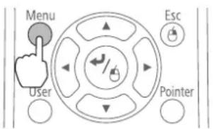
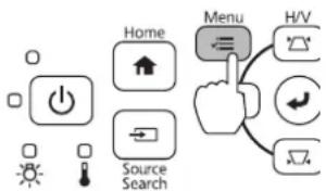
- Press the [Menu] button on the remote control or control panel.
Remote Control Control Panel
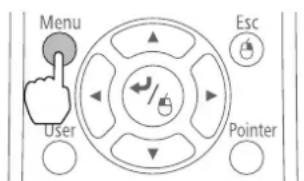
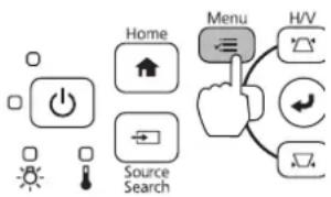
- Select Settings.
- Select Installation Guide.
- Select the current aspect ratio.
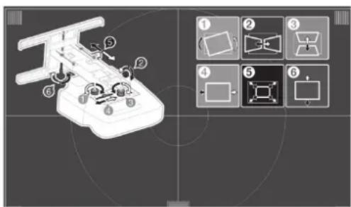
The installation guide and test pattern are displayed. Use these to monitor the image as you make the adjustments in steps ⑤ to ⑩.

To display the test pattern on the BrightLink 475Wi/480i/485Wi/575Wi/575Wi+/585Wi/585Wi+/595Wi/595Wi+, BrightLink Pro 1410Wi/1420Wi/1430Wi, and PowerLite 470/475W/480/485W/570/575W/580/585W, press the [Help] button on the remote control or control panel. Then, press the Ⓗ button on the remote control or the [Wide] button on the control panel.

Adjust the focus
- Slide the air filter cover switch () to open the air filter cover (). ②
- Use the focus lever to adjust the focus ()③
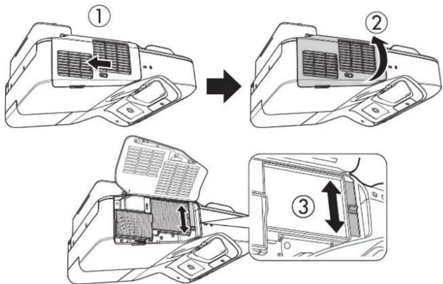
- After you finish making the adjustment, close the air filter cover.

Use the adjustment dial on the left side to adjust the horizontal roll

Repeat steps ⑤ to ⑩ as necessary.
- Loosen the lower adjustment dial ().①
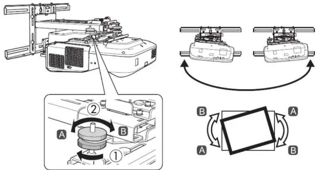
- Turn the upper adjustment dial to adjust the horizontal roll ( ).②
- After you finish making all of the adjustments in steps ⑤ to ⑩, tighten the lower adjustment dial you loosened in ①

Use the adjustment knob on the right side to adjust the horizontal rotation
- Loosen the screw to unlock the adjustment knob ().①
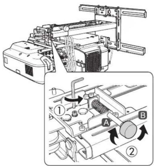
-
Turn the adjustment knob to adjust the horizontal rotation ().②
-
After you finish making all of the adjustments in steps ⑤ to ⑩, tighten the screw you loosened in ①.

Use the adjustment dial on the top to adjust the vertical tilt
- Loosen the lower adjustment dial ().①
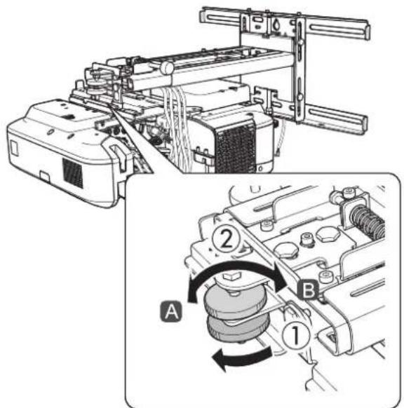
-
Turn the upper adjustment dial to adjust the vertical tilt ().②
-
After you finish making all of the adjustments in steps ⑤ to ⑩, tighten the lower adjustment dial you loosened in ①

Adjust the horizontal slide
- Loosen the M4 × 12 mm hexagon socket head cap bolt ().①
- Adjust the slider for the slide plate ().②
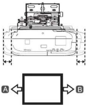
natural_image
Technical line drawing of a tank with labeled components and directional arrows (no text or symbols present)- After you finish making all of the adjustments in steps socket head cap bolt you loosened in ①
⑤ to ⑩, tighten the M4 × 12 mm hexagon

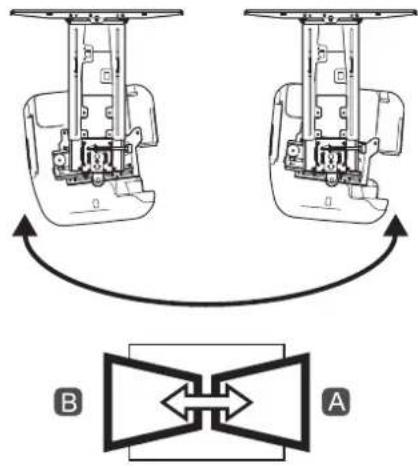
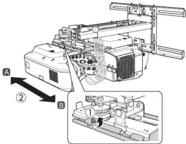
Adjust the forward/backward slide
- Loosen the M4 × 12 mm hexagon socket head cap bolts (×2) ().①
- Adjust the slider for the wall mount ().②
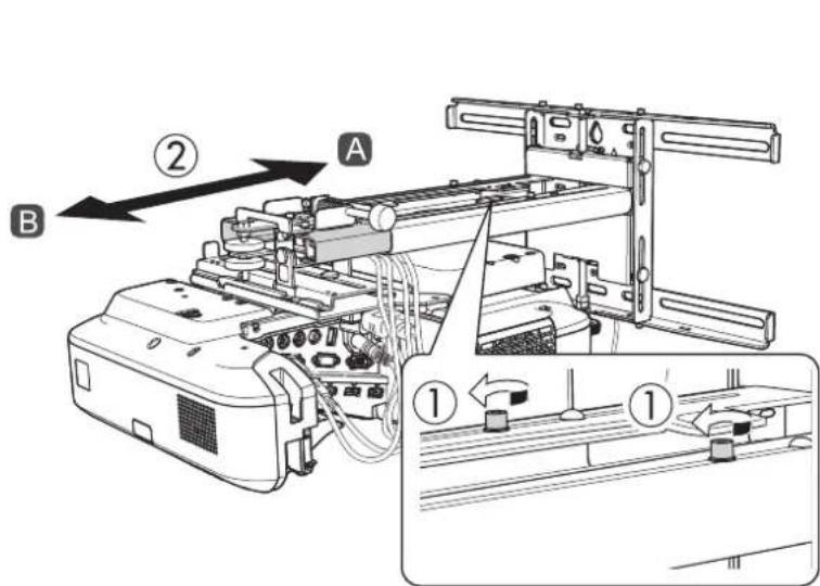
natural_image
Technical line drawing of a mechanical device with two views showing internal components and alignment arrows (no text or symbols)B
- After you finish making all of the adjustments in steps socket head cap bolts (×2) you loosened in ①
⑤ to ⑩, tighten the M4 × 12 mm hexagon
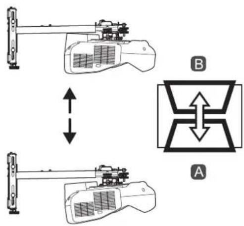
10 Adjust the vertical slide
-
Loosen the M6 × 20 mm hexagon shoulder bolt ().①
-
Adjust the vertical slide with the M8 hexagon bolt at the bottom of the wall mount, or the hexagonal shaft at the top of the wall mount (⑫)
Tightening the M8 hexagon bolt lowers the wall mount, and loosening the bolt raises it. Tightening the hexagonal shaft raises the wall mount, and loosening the shaft lowers it.
- After you finish making your adjustments, tighten the M6 × 20 mm hexagon shoulder bolt you loosened in ①
11 Re-adjust the focus
-
Slide the air filter cover switch () to open the air filter cover (). ②
-
Use the focus lever to adjust the focus ( ).③
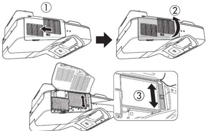
- After you finish making the adjustment, close the air filter cover.

Turn off the display of the test pattern
Press the [Esc] button on the remote control or control panel to turn off the test pattern.

Warning
Tighten all screws firmly. Otherwise, the projector or wall mount may fall and cause personal injury or property damage.

Attach the wall plate cover and end cap
If you need to use a security cable, make sure you attach it before installing the wall plate cover. See page 45 for instructions.
- Attach the right wall plate cover () first, then attach the left wall plate cover (). Snap the tabs on the cover into the holes on the wall plate. (If you need to remove the cover, press the tabs.)
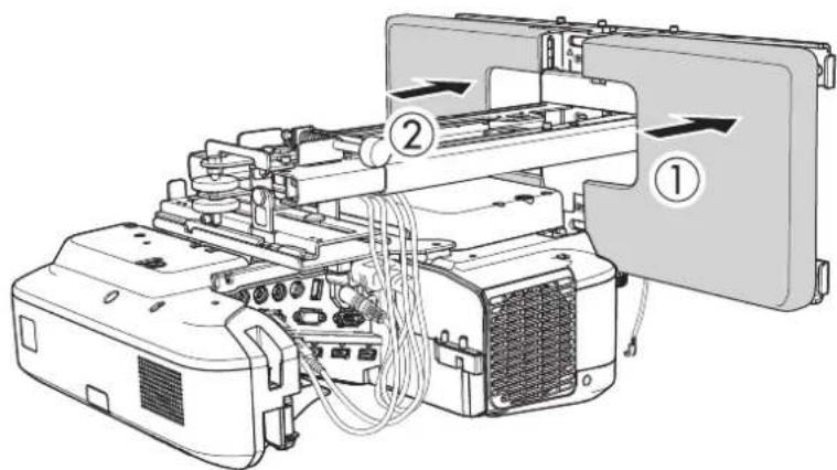

Depending on how the cables are wired, you may need to cut out parts of the wall plate cover to allow the cables to be passed through it.
When cutting the thin section of the wall plate cover and passing the cables through, make sure you perform deburring to smooth off any sharp edges to prevent damaging the cables.
Also, make sure you operate the cutter safely.
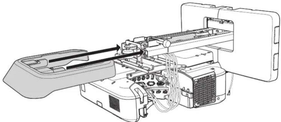
- Attach the end cap to the mount arm.
natural_image
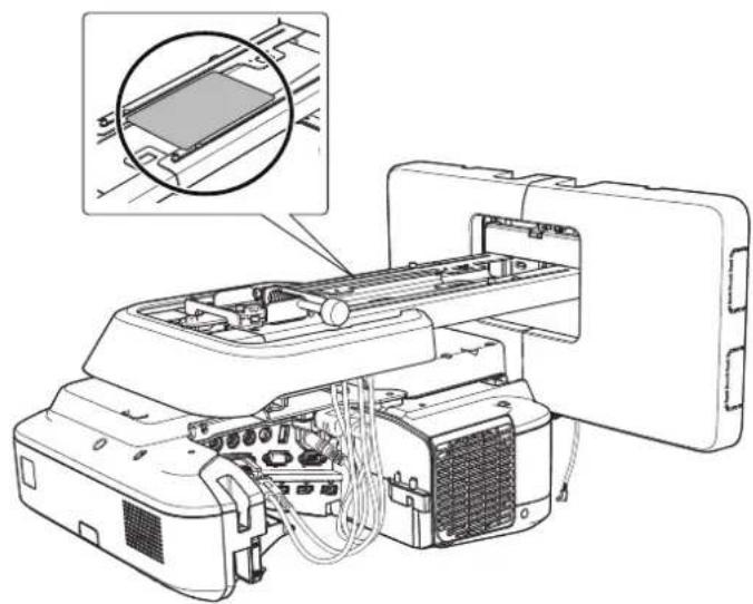
Technical line drawing of an electronic device internal structure with no visible text or symbolsIf you want to hide the gap in the mount arm, place the masking sticker over the gap.
natural_image
Technical line drawing of an electronic device with internal components and a magnified inset showing a component detail (no text or symbols present)
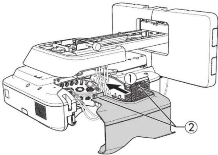
Attach the cable cover to the projector
Attach the cable cover (①) and use a cross-head screwdriver to tighten the screws (x2) and secure the cable cover (⑫)

Caution
Only a specialist should remove or reinstall the projector, including for maintenance and repairs. Refer to your projector's User's Guide for instructions on maintenance and repairs.

Warning
☐ Never loosen the bolts and nuts after installation. If you find any loose screws, tighten them firmly. Otherwise, the projector or wall mount may fall and cause personal injury or property damage.
☐ Do not hang on the wall mount or hang a heavy object on the wall mount. If the projector or wall mount falls, it could cause personal injury or property damage.
Installing the Touch Unit and Control Pad
For details on installing the Touch Unit and Control Pad for your product (if applicable), see the documentation that came with your projector.
Using the Easy Interactive Function
After you install your BrightLink model (and the Touch Unit, if applicable), you need to perform calibration to align the positions of the cursor and your interactive pen(s) (and finger, if the Touch Unit is installed). See the projector's online User's Guide or Start Here folder for detailed instructions.
In order to use the Easy Interactive Tools software, you must first install the software on your computer. OS X users also need to install a driver that enables pen or finger touch interactivity to work. Both software programs are included with the BrightLink projector.
For details, see the online User's Guide or visit:
U.S.: www.epson.com/support/brightlinkdownloads
Canada: www.epson.ca/support/brightlinkdownloads
Latin America: www.epson.com.jm/support (website available only in Spanish)
Correcting the Image Shape on a Curved Screen
If you are projecting on a curved screen, adjust the Arc Correction setting to correct the image shape.

Touch unit installation requires a projection surface that is flat, smooth, and unwarped with no more than 0.2 inches (5 mm) of unevenness in any direction on the screen surface.
- Press the [Menu] button on the remote control or control panel.
Remote Control Control Panel
- Select Settings.
- Select Geometric Correction.
- Select Arc Correction.
-
Select Arc Correction.
-
Select the area that you want to correct.
![[Arc Correction] Select the area.](/content/2026/04/644405/images/ec209ed4ce3654799e6f8e526b317db1f12925f1b1eef41ac1796e359ac79d61.jpg)
- Use the arrow buttons on the remote control or control panel to change the shape of the selected area.
![[Arc Correction] Perform the adjustment.](/content/2026/04/644405/images/6c46aac0a32f28c8c768a70a8f6bd1a05e523d314eb079b9ee6d0d4e5d923994.jpg)
- Repeat steps 6 and 7 to adjust any additional areas.
Attaching a Security Cable
If the projector is to be installed in a room where it will be left unattended, you can use a commercially available theft-prevention wire lock to secure the projector to a post or other object to prevent someone from taking it.
Pass the wire for the theft-prevention wire lock through the security cable installation point.
For details on how to lock the wire lock, refer to the User's Guide supplied with the wire lock.
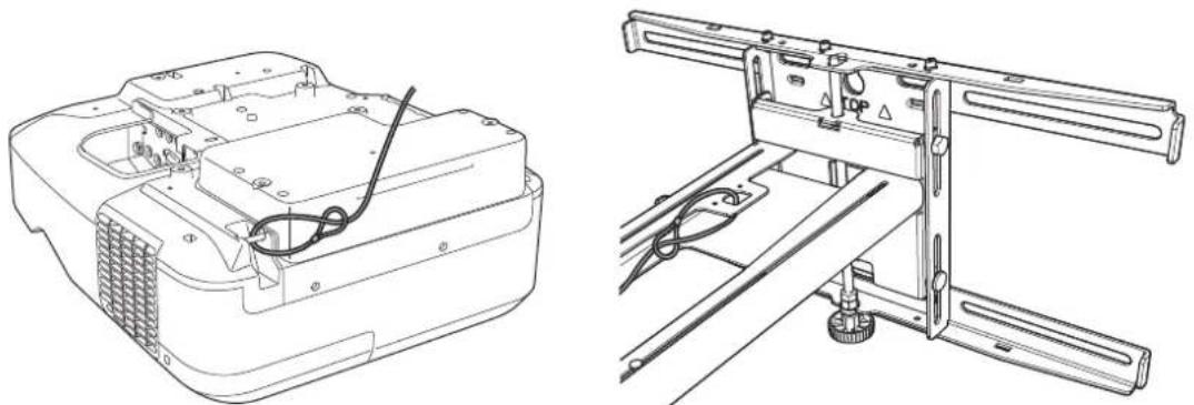
natural_image
Technical line drawings of an electronic device with internal components and wiring (no text or symbols)Make sure you leave the remote control, batteries, CDs, interactive pen(s), pen batteries, pen tray, and battery charger in the room with the projector. If your projector came with a product-specific installation guide or an installation leave-behind list, use that list instead of this one. The accessories included with the projector vary by model and region.
Limited Warranty
Two-Year Limited Warranty
What Is Covered: Epson America, Inc. ("Epson") warrants to the original retail purchaser of the Epson product enclosed with this limited warranty statement that the product, if purchased new and operated in the United States, Canada, or Puerto Rico will be free from defects in workmanship and materials for a period of two years from the date of original purchase. For warranty service, you must provide proof of the date of original purchase.
What Epson Will Do To Correct Problems: If your product requires service during the limited warranty period, please call Epson at the number on the bottom of this statement and be prepared to provide the model, serial number (if applicable), and date of original purchase. If Epson confirms that warranty service is required, Epson will, at its option, repair or replace the defective unit, without charge for parts or labor. If Epson authorizes an exchange for the defective unit, Epson will ship a replacement product to you, freight prepaid, so long as you use an address in the United States, Canada, or Puerto Rico. You are responsible for securely packaging the defective unit and returning it to Epson within five working days of receipt of the replacement. Epson requires a debit or a credit card number to secure the cost of the replacement product in the event that you fail to return the defective one. If Epson authorizes repair instead of exchange, Epson will direct you to send your product to Epson or its authorized service center, where the product will be repaired and sent back to you. You are responsible for packing the product and for all postage or shipping costs to and from the Epson authorized service center. When warranty service involves the exchange of the product or of a part, the item replaced becomes Epson property. The exchanged product or part may be new or refurbished to the Epson standard of quality. If service cannot be provided on the product for any reason and Epson no longer sells the same model, Epson will replace your product with a model of equal or superior value. Replacement products or parts assume the remaining warranty period of the original product.
What This Warranty Does Not Cover: This warranty covers only normal use in the United States, Canada, or Puerto Rico. This warranty does not cover the following:
• Excessive continual use
- Consumables
• Installation or removal
- Cosmetic damage caused by handling or normal wear and tear during usage
- Damage caused by failure to properly maintain the product (see your online User's Guide for details)
- Damage caused by interaction with non-Epson products
- Any problem resulting from misuse, abuse, improper installation, neglect, improper shipping, disasters such as fire, flood, and lightning, improper electrical current, software problems, exposure to chemical smoke, or excessive humidity
Any problem resulting from service by other than Epson or an Epson Authorized Servicer
Epson is not responsible for warranty service should the Epson label or logo or the rating label or serial number be removed. This warranty is not transferrable. Epson is not responsible for your data or applications, which cannot be restored and should be backed up by you. Postage, insurance, or shipping costs incurred in presenting your Epson product for carry-in warranty service are your responsibility. If a claimed defect cannot be identified or reproduced in service, you will be held responsible for costs incurred.
DISCLAIMER OF OTHER WARRANTIES: THE WARRANTY AND REMEDY PROVIDED ABOVE ARE EXCLUSIVE AND IN LIEU OF ALL OTHER EXPRESS OR IMPLIED WARRANTIES INCLUDING, BUT NOT LIMITED TO, THE IMPLIED WARRANTIES OF MERCHANTABILITY, NONINFRINGEMENT OR FITNESS FOR A PARTICULAR PURPOSE. SOME LAWS DO NOT ALLOW THE EXCLUSION OF IMPLIED WARRANTIES. IF THESE LAWS APPLY, THEN ALL EXPRESS AND IMPLIED WARRANTIES ARE LIMITED TO THE WARRANTY PERIOD IDENTIFIED ABOVE. UNLESS STATED HEREIN, ANY STATEMENTS OR REPRESENTATIONS MADE BY ANY OTHER PERSON OR FIRM ARE VOID.
EXCLUSION OF DAMAGES; EPSON'S MAXIMUM LIABILITY: IN NO EVENT SHALL EPSON OR ITS AFFILIATES BE LIABLE FOR ANY SPECIAL, INCIDENTAL, OR CONSEQUENTIAL DAMAGES OR ANY LOST PROFITS RESULTING FROM THE USE OR INABILITY TO USE THE EPSON PRODUCT, WHETHER RESULTING FROM BREACH OF WARRANTY OR ANY OTHER LEGAL THEORY. IN NO EVENT SHALL EPSON OR ITS AFFILIATES BE LIABLE FOR DAMAGES OF ANY KIND IN EXCESS OF THE ORIGINAL RETAIL PURCHASE PRICE OF THE PRODUCT.
Arbitration, Governing Laws: Any dispute, claim or controversy arising out of or relating to this warranty shall be determined by arbitration in Los Angeles County, California before a single arbitrator. The arbitration shall be administered by JAMS pursuant to its Comprehensive Arbitration Rules and Procedures. Judgment on the
award may be entered in any court having jurisdiction. Any action must be brought within three months of the expiration of the warranty. This clause shall not preclude parties from seeking provisional remedies in aid of arbitration from a court of appropriate jurisdiction. This warranty shall be construed in accordance with the laws of the State of California, except this arbitration clause which shall be construed in accordance with the Federal Arbitration Act.
Other Rights You May Have: This warranty gives you specific legal rights, and you may also have other rights which vary from jurisdiction to jurisdiction. Some jurisdictions do not allow limitations on how long an implied warranty lasts, or allow the exclusion or limitation of incidental or consequential damages, so the above limitations or exclusions may not apply to you.
In Canada, warranties include both warranties and conditions.
To find the Epson Authorized Reseller nearest you, please visit www.epson.com (U.S.) or www.epson.ca (Canada).
To find the Epson Customer Care Center nearest you, please visit www.epson.com/support (U.S.) or www.epson.ca/support (Canada).
To contact the Epson Connection ^SM , please call (562) 276-4394 in the U.S. and (905) 709-3839 in Canada or write to Epson America, Inc., P.O. Box 93012, Long Beach, CA 90809-3012.
natural_image
Technical line drawing of a mechanical component with no visible text or symbolsSupport de montage
natural_image
Technical line drawing of a rectangular electrical component with mounting flanges (no text or symbols)Plaque murale
natural_image
Two technical line drawings of mechanical parts, one showing a cut and the other a flanged section (no text or symbols)Cache de la plaque murale
natural_image
Technical line drawing of a mechanical clamp or fixture with gears and lever (no text or symbols)
natural_image
Technical line drawing of a mechanical assembly with internal components and a close-up inset (no text or symbols)natural_image
Technical line drawing of a mechanical assembly with internal components and a close-up inset showing internal wiring (no text or symbols)Distance entre la surface de projection et la plaque murale
natural_image
Pure line drawing of a twisted rope or helix without any text, numbers, or symbolsnatural_image
Diagram of a funnel emitting particles through a pipe with directional arrows indicating flow (no text or labels)natural_image
Diagram showing a mechanical assembly with a bolt and nut inserted into a connector (no text or symbols present)natural_image
Technical diagram showing a wrench inserted into a bolt, with directional arrows indicating movement or force (no text or symbols present)- Retirez la vis temporaire de la plaque murale.


natural_image
Technical line drawing of a mechanical assembly with attached components and a close-up inset showing a hand holding a cylindrical component (no text or symbols present)
natural_image
Technical diagram of a mechanical assembly with internal components and a magnified inset showing a tool interacting with a component (no text or labels present)
Avertissement
natural_image
Technical line drawing of a mechanical assembly with no visible text or symbols
natural_image
Diagram of two identical mechanical components with curved arrows indicating rotation or flow (no text or symbols)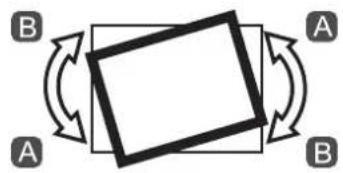
flowchart
graph TD
    A[" "] --> B[" "]
    B --> C[" "]
    C --> A
    style A fill:#f9f,stroke:#333
    style B fill:#ccf,stroke:#333
    style C fill:#cfc,stroke:#333
natural_image
Technical line drawing of a mechanical device with two views showing internal components (no text or symbols)
flowchart
graph TD
    A["A"] --> B["B"]
    A --> C["C"]
    A --> D["D"]
    A --> E["E"]
