
ELPMBC03 - Projector EPSON - Free user manual and instructions
Find the device manual for free ELPMBC03 EPSON in PDF.

| Brand | Epson |
| Model | ELPMBC03 |
| Product Type | Extension column for projector mount |
| Use | Ceiling mounting of projectors or screens |
| Material | Aluminum or steel (according to ASTM B221 standard) |
| Fixed Length | 76 mm (3 in) or 152 mm (6 in) depending on version |
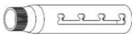
| Adjustable Length | From 229 to 305 mm (9 to 12 in) |
| Outer Diameter | 58.7 mm (2.31 in) for fixed column; 48.3 mm (1.90 in) for adjustable column |
| Maximum Load Capacity | 226 kg (500 lb) |
| Thread Type | NPT 1 3/4 in (aligned on 4 full threads) |
| Compatibility | Ceiling plates and mounts ELPMBP04, ELPMBP05, ELPMBP06, ELPMBP07, ELPMBPRH |
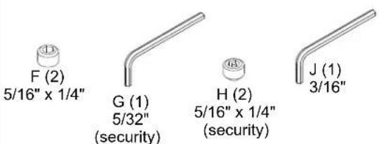
| Included Parts | Column (A), fixing screws (C, D, E, F, G, H), hex key (J) |
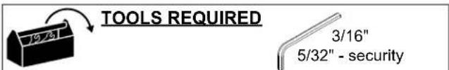
| Required Tools | 3/16 in and 5/32 in hex keys (security) |
| Installation | Indoor only; do not use outdoors |
| Warranty | 10 years (non-electrical products) |
| Standards | ANSI/ASME B1.20.1 (Schedule 40) |
| Manufacturer | Milestone AV Technologies |
| Distributor | Epson America, Inc. |
| Manufacturer Reference | 8800-002773 Rév01 |
Frequently Asked Questions - ELPMBC03 EPSON
User questions about ELPMBC03 EPSON
0 question about this device. Answer the ones you know or ask your own.
Ask a new question about this device
Download the instructions for your Projector in PDF format for free! Find your manual ELPMBC03 - EPSON and take your electronic device back in hand. On this page are published all the documents necessary for the use of your device. ELPMBC03 by EPSON.
USER MANUAL ELPMBC03 EPSON
ELPMBC02 / ELPMBC03 / ELPMBC04 9-12" (229-305mm) Adjustable Length Column 6" (152mm) Fixed Extension Column 3" (76mm) Fixed Extension Column
DISCLAIMER
Milestone AV Technologies and its affiliated corporations and subsidiaries (collectively "Milestone"), intend to make this manual accurate and complete. However, Milestone makes no claim that the information contained herein covers all details, conditions or variations, nor does it provide for every possible contingency in connection with the installation or use of this product. The information contained in this document is subject to change without notice or obligation of any kind. Milestone makes no representation of warranty, expressed or implied, regarding the information contained herein. Milestone assumes no responsibility for accuracy, completeness, or sufficiency of the information contained in this document.

IMPORTANT SAFETY INSTRUCTIONS

WARNING: A WARNING alerts you to the possibility of serious injury or death if you do not follow the instructions.

CAUTION: A CAUTION alerts you to the possibility of damage or destruction of equipment if you do not follow the corresponding instructions.

WARNING: Failure to read, thoroughly understand, and follow all instructions can result in serious personal injury, damage to equipment, or voiding of factory warranty! It is the installer's responsibility to make sure all components are properly assembled and installed using the instructions provided

WARNING: Failure to provide adequate structural strength for this component can result in serious personal injury or damage to equipment! It is the installer's responsibility to make sure the structure to which this component is attached can support five times the combined weight of all equipment. Reinforce the structure as required before installing the component.

WARNING: Exceeding the weight capacity can result in serious personal injury or damage to equipment! It is the installer's responsibility to make sure the combined weight of all components attached to the ELPMBC02/ELPMBC03/ELPMBC04 does not exceed 500 lbs (226 kg).
- The weight capacity of the ELPMBC02/ELPMBC03/ELPMBC04 may be LIMITED to the lowest weight capacity of any other component or accessory used within the mounting system.

WARNING: Do not use this product outdoors.

WARNING: Use this mounting system only for its intended use as described in these instructions. Do not use attachments not recommended by the manufacturer.

WARNING: Never operate this mounting system if it is damaged. Return the mounting system to a service center for examination and repair.
NOTE: ELPMBC02/ELPMBC03/ELPMBC04 are Listed for use with ELPMBP04, ELPMBP05, ELPMBP06, ELPMBP07 AND ELPMBPRH ceiling plates and mounts specified for use with 1-1/2" NPT following ANSI/ASME B1.20.1 (Schedule 40, 0.154" minimum thickness, steel or aluminum - ASTM B221) extension columns. ELPMBC02 / ELPMBC03 / ELPMBC04 extension columns are suitable for a maximum 500 lbs (226 kg).
--SAVE THESE INSTRUCTIONS--

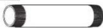

A (1) [Fixed length]
OR
A (1) [Adjustable length]
NOTE: Parts B-J are only included with adjustable length columns.
B (1)
C (1) 5/16" x 5/8"

D (1) 5/16"

E (1) 5/16"

FIXED LENGTH EXTENSION COLUMN
IMPORTANT ! : The following procedure assumes that the ceiling plate/adapter (not included) has been properly installed following instructions provided with ceiling plate/adapter.
NOTE: Intended for use with Chief accessories and mounts.
- Install 1-1/2" NPT threaded column (A) into plate/adapter (See Figure 1). Securely tighten column.
- Ensure column (A) engages four full threads into plate/adapter.
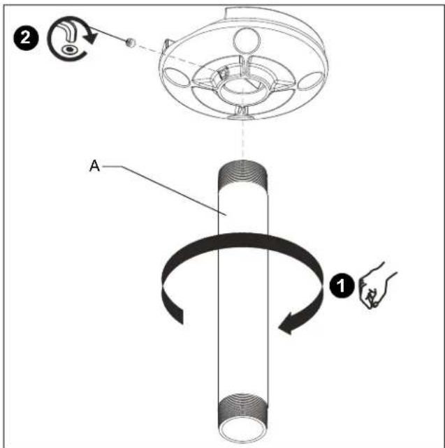
Figure 1
- Secure column (A) by tightening set screw in plate/adapter (See Figure 1).
NOTE: Hex key and set screw provided with plate/adapter.

WARNING: Exceeding the weight capacity can result in serious personal injury or damage to equipment! It is the installer's responsibility to make sure the combined weight of all components attached to the ELPMBC02/ELPMBC03/ELPMBC04 columns do not exceed 500 lbs (226 kg).
- The weight capacity of the ELPMBC02/ELPMBC03/ELPMBC04 columns may be LIMITED to the lowest weight capacity of any other component or accessory used within the mounting system.
- Install and secure projector/display mount (not included) to lower end of column (A) following instructions included with mount.
ADJUSTABLE LENGTH EXTENSION COLUMN
IMPORTANT ! : The following procedure assumes that the ceiling plate/adapter (not included) has been properly installed following instructions provided with ceiling plate/adapter.
NOTE: Intended for use with Chief accessories and mounts.
- Install 1-1/2" NPT threaded column (A or B, as applicable) into plate/adapter (See Figure 2). Securely tighten column. • Ensure column (A or B, as applicable) engages four full threads into plate/adapter.

Figure 2
- Secure column (A or B, as applicable) by tightening set screw in plate/adapter (See Figure 2).
NOTE: Hex key and set screw provided with plate/adapter.
-
Install mating column (A or B, as applicable) (See Figure 2).
-
Using key (J), loosely install screw (C) through lock washer (D), flat washer (E), and outer column (B) into adjustment hole in inner column (A) (See Figure 3).
NOTE: Two adjustment holes provided in columns 6" or longer (152mm) in length. Either adjustment hole can be used to provide 1" (25mm) adjustment increments.
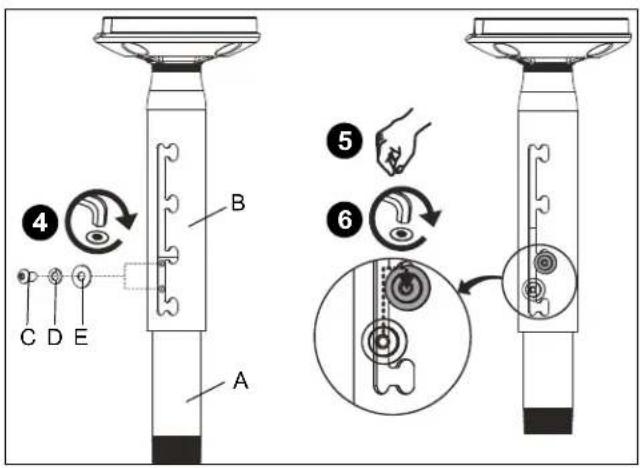
Figure 3
- Adjust column (A or B, as applicable) to desired length, then rotate and lock into position (See Figure 3).
NOTE: Any locking slot can be used to provide 2" (51mm) adjustment increments. - Tighten screw (C) using key (J) (See Figure 3).
- Install and tighten set screws (standard (F) or security (G), as desired) using key (J) (See Figure 4).

Figure 4
- Install and secure projector/display mount (not included) to lower end of column (A or B, as applicable) following instructions included with mount.
DIMENSIONS

Adjustable Length Column
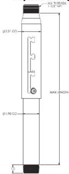
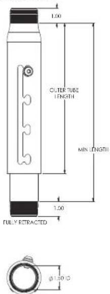
DIMENSIONS: INCH
LIMITED WARRANTY
With the exception of electrical products, Milestone warrants its products to be free of defects in material and workmanship for 10 years. All warranties are in effect beginning the date the product was invoiced by Milestone. Electrical mechanisms (such as lift products) have a 1-year limited warranty. All warranties are in effect for the original purchaser only. Milestone disclaims liability for any modifications, improper installation and/or installations over the specified weight capacity. Milestone also disclaims liability for any modifications made to electrical mechanisms, improper installation, incorrect voltage connection and/or installations over the stated weight capacity. All Electrical Mechanisms are intended for indoor use only and failure to comply will void warranty. Milestone's sole warranty obligation to the owner of its products is to repair or replace (at Milestone's discretion) defective products at no charge to the original purchaser within the warranty period. The purchaser is responsible for returning the product to Milestone via prepaid shipping. To the maximum extent permitted by applicable law, Milestone disclaims any other warranties, express or implied, including warranties of fitness for a particular purpose and warranties of merchantability. Milestone will not be liable for any damages whatsoever arising out of the use or inability to use Milestone products, even if Milestone has been advised of the possibility of such damages. Milestone bears no responsibility for incidental or consequential damages. This includes, but is not limited to, any labor charges for the repair of Milestone products performed by someone other than a Milestone employee. Because some states and jurisdictions do not allow the exclusion or limitation of liability for consequential or incidental damages, the above limitation may not apply. Milestone will not be responsible for damage to Milestone products caused by misuse, abuse, failure to properly package the product for return to Milestone or for damage caused by carriers during shipment to or from Milestone. Any repairs to Milestone products required due to misuse, abuse or shipping damage or repairs of defective Milestone product outside the warranty period will be performed at the current rates established by Milestone for factory service.
Distributed by:
Epson America, Inc.
3840 Kilroy Airport Way
Long Beach, CA 90806
Manufactured by:
Milestone AV Technologies
A 6436 City West Parkway, Eden Prairie, MN 55344
P 800.582.6480
F 877.894.6918
E info@milestone.com (Tech Support 7:00am - 7:00pm CST)
www.milestone.com
8800-002773 Rev01
09/15

ELPMBC02 / ELPMBC03 / ELPMBC04
Figure 1
Figure 2
Figure 4
Figura 1
Figura 2
Figura 4
D 6436 City West Parkway, Eden Prairie, MN 55344
T 800.582.6480
F 877.894.6918
C (1)
5/16" x 5/8"
D (1)
5/16"


F (2)
5/16" x 1/4"


Figura 1
Figura 2
Figura 4
A 6436 City West Parkway, Eden Prairie, MN 55344
T 800.582.6480
F 877.894.6918


- ELPMBC02 / ELPMBC03 / ELPMBC04 9-12" (229-305mm) Adjustable Length Column 6" (152mm) Fixed Extension Column 3" (76mm) Fixed Extension Column
- DISCLAIMER
- IMPORTANT SAFETY INSTRUCTIONS
- --SAVE THESE INSTRUCTIONS--
- FIXED LENGTH EXTENSION COLUMN
- ADJUSTABLE LENGTH EXTENSION COLUMN
- LIMITED WARRANTY
- ELPMBC02 / ELPMBC03 / ELPMBC04
Brand : EPSON
Model : ELPMBC03
Category : Projector