
DTI 1127 X - Hob DE DIETRICH - Free user manual and instructions
Find the device manual for free DTI 1127 X DE DIETRICH in PDF.

| Product type | Gas and induction hob |
| Brand | DE DIETRICH |
| Model | DTI 1127 X |
| Overall dimensions (W x D x H) | 65 cm x 51.8 cm x 5 cm |
| Cutout dimensions (W x D x H) | 54.9 cm x 47 cm x 5.9 cm |
| Weight | 11.4 kg |
| Electrical supply | 220-240 V~ / 50 Hz, max power 3100 W (induction) |
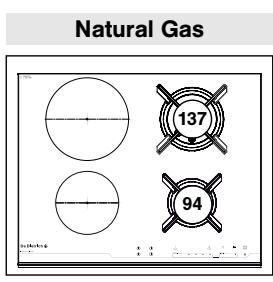
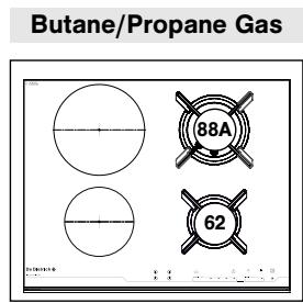
| Gas supply | Natural gas (G20/G25) or butane/propane (G30/G31), total power 4.65 kW |
| Gas burners | 2 burners: one semi-rapid (1.5 kW) and one large rapid (3.1 kW) Interchangeable injectors for natural gas and butane/propane |
| Induction zones | 2 zones: one Ø210 mm (3100 W) and one Ø160 mm (2000 W) |
| Controls | Touch controls with power and timer sliders |
| Main functions | Independent or cooking-linked timer, 'Elapsed Time' function, power presets, child lock, Clean Lock |
| Safety | Automatic shut-off (AS), small object detection, overflow protection, automatic extinction, thermocouple, temperature limiter |
| Residual heat indicator | 'H' display as long as the zone is hot |
| Maintenance and cleaning | Clean with a soft sponge and hot water, special ceramic hob products, do not use abrasive sponge or steam cleaner |
| Spare parts and repairability | Certified original parts available, repairs by a qualified professional |
| Installation | Recessed into a cabinet with min. 3 cm thickness, cutout 56 cm x 49 cm, requires minimum ventilation of 15.4 m³/h |
| Induction cookware compatibility | Enameled steel, cast iron, suitable stainless steel, special-base aluminum; check the induction logo |
Frequently Asked Questions - DTI 1127 X DE DIETRICH
User questions about DTI 1127 X DE DIETRICH
0 question about this device. Answer the ones you know or ask your own.
Ask a new question about this device
Download the instructions for your Hob in PDF format for free! Find your manual DTI 1127 X - DE DIETRICH and take your electronic device back in hand. On this page are published all the documents necessary for the use of your device. DTI 1127 X by DE DIETRICH.
USER MANUAL DTI 1127 X DE DIETRICH
- RELATIONS CONSOMMATEURS
DE 146 When you discover De Dietrich products you experience feelings that only objects of value can arouse.
You are immediately attracted as soon as you see them. The quality of the design is illustrated by its timelessness, degree of refinement and elegance, and high standard of finish, resulting in perfect harmony between different appliances.
Then comes the irresistible urge to touch. De Dietrich design makes the most of sturdy and noble materials; priority is given to authenticity.
By combining the most advanced technologies with the best materials, De Dietrich makes products of the highest quality for the benefit of all those who love cooking.
We hope you are extremely satisfied with this new appliance and will be happy to receive your suggestions and to answer your questions. Please contact our customer service department or use our Internet site.
We invite you to register your product at www.de-dietrich.com to take advantage of all the benefits the brand has to offer.
Thanking you for your confidence.
De Dietrich
Find further details on the brand at www.de-dietrich.com Visit La Galerie De Dietrich, 6 rue de la Pétinière in Paris Open Tuesday to Saturday 10 a.m. to 7 p.m.
De Dietrich Customer Service 0892 02 88 04
1/USERNOTICES
- Safety instructions 40
- Respect for the environment 41
Description of your appliance 42 - Layout of the control panel 43
- Selector touch controls 43
- Adjustment touch controls 43
2/ INSTALLING YOUR APPLIANCE
- Tips for flush mounting 44
- Electrical connection 47
Gas connection 48 - Changing the gas supply 50
3/ USING YOUR APPLIANCE
- Description of your hob 54
Using a cooking zone 55
Using the timer while cooking 57
Using the timer on its own 58 - Using the "ELAPSED TIME" function 56
- Using the power presets 60
Child safety 61 - Clean Lock 61
-Operating safety 62
Cookware to be used with gas burners 63
·Induction-safe cookware 64
4/ DAILY CARE OF YOUR APPLIANCE 66
5/ SMALL FAULTS AND PROBLEMS 67
6/ COOKING CHART FOR GAS BURNERS 70
7/ COOKING CHART FOR INDUCTION ZONES 71
8/ AFTER-SALES SERVICE AND CUSTOMER RELATIONS
·Service calls 72
- Customer relations 72

Important
Keep this user guide with your appliance. If the appliance is ever sold or transferred to another person, ensure that the new owner receives this user guide. Please become familiar with these recommendations before installing and using your oven. They were written for your safety and the safety of others.
SAFETY GUIDELINES
- We have designed this cooking hob for use by private individuals in their homes.
- This hob must be installed in accordance with current regulations and used only in a well-ventilated area. Consult this guide before installing and using your appliance.
- Never leave the appliance unattended when in use.
- These cooking hobs are intended exclusively for cooking beverages and foodstuffs and do not contain any asbestos-based materials.
- This appliance is not connected to a combustion by-product disposal system. It must be installed and connected in accordance with current regulations. Special attention should be given to regulations regarding the proper levels of ventilation.
- Intensive, prolonged use of the appliance may require additional ventilation; you can, for example, open a window or provide more effective ventilation by increasing the setting of the mechanical ventilation system, if you have one.
- Do not store CLEANING or FLAMMABLE products (aerosol cans, pressurised containers, papers, cookbooks, etc.) in the area underneath your hob.
- If the hob has been installed over a drawer, we recommend that you avoid using it to store flammable items (plastics, papers, aerosol cans, etc.).
- Your hob must be disconnected from the power supply (electricity and gas) before undertaking any repair work.
- If you plug electrical appliances into a socket close to the hob, ensure that no cable comes into contact with the hotplates and burners.
- As a safety measure, remember to shut off the mains gas supply or the butane/propane gas cylinder when not in use.
The CE mark is affixed to these hobs.
- Installation should only be undertaken by qualified fitters and technicians.
Before installation, ensure that the conditions of local distribution (gas type and pressure) and the settings of the appliance are compatible.
- As part of our commitment to constantly improving our products, we reserve the right to make changes to them based on technological advances to their technical, functional and/or aesthetic properties.
- Using a gas cooking appliance generates heat and humidity in the room where it is installed. Please ensure that your kitchen has proper ventilation: keep natural ventilation outlets open or install a mechanical device (mechanical ventilation hood).
SAFETY GUIDELINES

Note
The default settings on your hob are for natural gas.
- The setting conditions for this hob are printed on a sticker inside the instruction guide pouch and on the packaging.
So that you can easily locate any reference numbers for your appliance, we recommend that you make a note of them on the "After-Sales Service and Customer Relations" page (this page also explains where this information may be found on your appliance).
- This appliance is not intended for use by persons (including children) with impaired physical, sensory or mental capacities, or by inexperienced or untrained persons, unless they have received prior instruction or supervision in its operation by a person responsible for their safety.
Children must be supervised to prevent them from playing with the appliance.
- This unit is not intended to be operated using an external timer or a separate remote control system.
- This hob complies with the EN 60335-2-6 standard relative to the heating of cabinets and the Class 3 standard relative to installation (according to the EN 30-1-1 standard).
-WARNING: If a crack appears in the surface of the glass, disconnect your appliance from the power supply to avoid electric shock.
CARING FOR THE ENVIRONMENT
- This appliance's packing materials are recyclable. Recycle them and help to protect the environment by disposing of them in the council receptacles provided for this purpose.
Your appliance also contains various recyclable materials. It is therefore marked with this logo to indicate that, in European Union countries, used appliances must not be mixed with other waste. Appliance recycling organised by your manufacturer will thus be
carried out in optimum conditions, in accordance with European directive 2002/96/EC on waste electrical and electronic equipment. Consult your local authority or your retailer to find the drop-off points for used appliances nearest to your home.
We thank you for your help in protecting the environment.
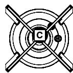
THE INDUCTION PRINCIPLE
- The induction principle is based on a magnetic effect.
When you place cookware on a cooking zone and turn the appliance on, the electronic circuits in the hob produce "induced" currents in the bottom of the cookware which instantly raise its temperature. This heat is then transmitted to the food
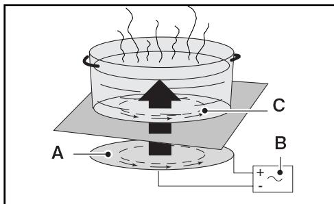
A - Induction plate
B - Electronic circuit
C - Induced currents
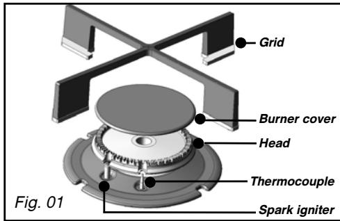
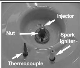
DESCRIPTION OF THE HOB

Burner covers

Spark igniter

Burner head

Thermocouple

Injector
LAYOUT OF THE CONTROL PANEL
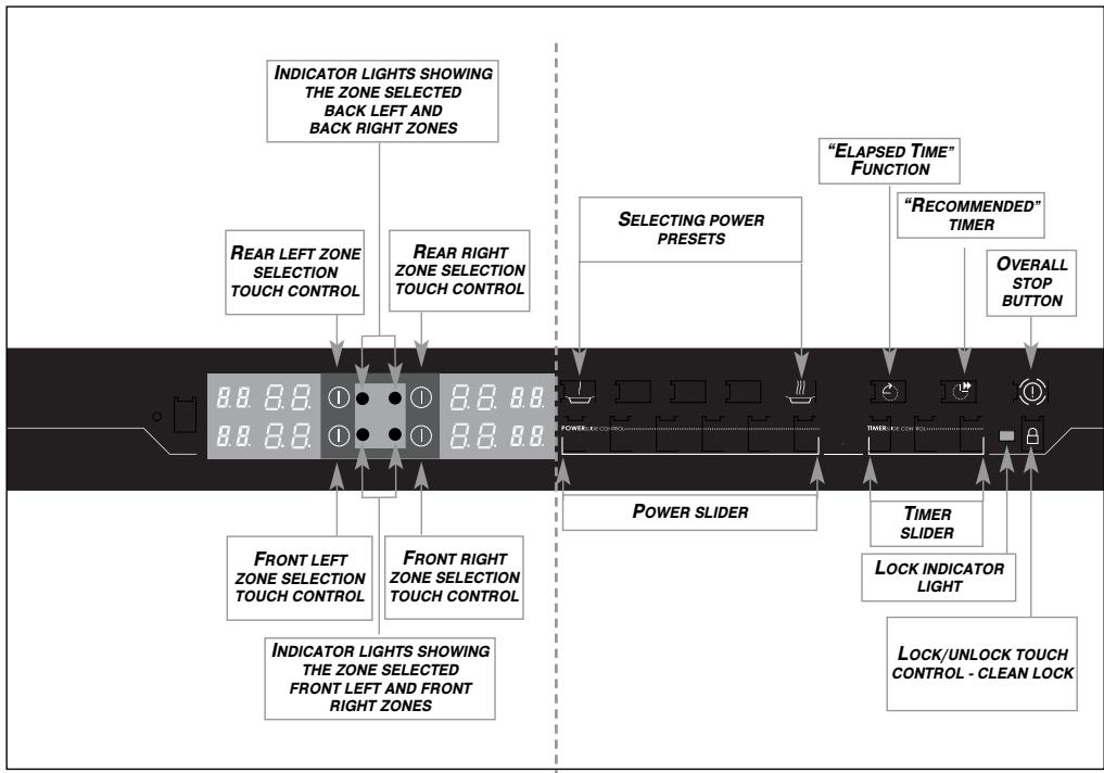
- SELECTOR TOUCH CONTROLS
These touch controls turn cooking zones on or off. When a zone is selected, the corresponding indicator lights up and you can then change its settings.
For a selected zone
Indicator for selected zone
On/off touch control
B. B. Power display
8.8. Timer display
ADJUSTMENT TOUCH CONTROLS
These touch controls allow you to adjust power, timer, programmer, etc. for each of the selected zones.
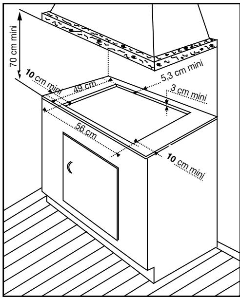
TIPS FOR FLUSH MOUNTING
| Model | Width | Depth | Thickness |
| Cabinet cut-out | 56 cm | 49 cm | Depending on cabinet |
| Overall dimensions above the work top | 65 cm | 51.8 cm | 5 cm |
| Overall dimensions below the work top | 55 cm | 47 cm | 51 cm |
Installation should only be undertaken by qualified fitters and technicians.
Before installation, ensure that the conditions of local distribution (gas type and pressure) and the settings of the appliance are compatible.
The setting conditions for this hob are printed on a sticker inside the instruction guide pouch and on the packaging.
As it is not connected to a system for removing combustion by-products, it must be installed in compliance with current regulations and used in a well-ventilated area. Special attention should be given to ventilation regulations.
In this regard, as combustion can only take place in the presence of the oxygen in the air, the latter must be continually renewed and combustion by-products evacuated (a minimum flow rate of 2m^3 /h per kW of gas power is required.
Example:
- Total power = 0.85 + 1.5 + 2.25 + 3.1 = 7.7 kW . 7.7 kW × 2 = 15.4 m^3 / h minimum air flow.
These tables comply with the heating of cabinets in accordance with standard EN 60335-2-6 and class 3 as regards the installation (in accordance with standard EN 30-1-1).
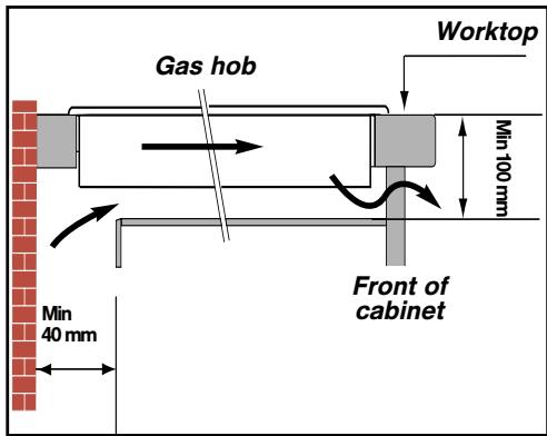
Your hob should be built into the top of a supporting cabinet. The worktop should be at least 3 cm thick, and made of a heat-resistant material or a material with a heat-resistant coating.
To ensure that cooking utensils can be handled safely, a minimum of 30~cm either side of the hob should be kept free from any obstructions (cabinets or walls).
If a horizontal partition is positioned under the hob, it must be located between 100 and 150~mm from the top of the work surface. In any event, do not store aerosol cans or containers under pressure in any compartment that may exist under the hob.
Place your hob in the opening of the support cabinet, carefully pulling the table towards you.
Reposition the pan supports, burner covers and burner heads.
Connect the hob's power cable to your kitchen's electricity supply (see "Connecting to the power supply" with regard to the hob).
If you wish, you can fix the hob in place using the four mounting brackets and screws supplied with the hob (see diagram opposite) by attaching them to the four corners of the housing.
You must use the holes provided for this.
Tighten the screws until the fixing bracket starts to pull out of shape. Do not use a power screwdriver.
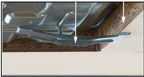
Mounting brackets
Worktop

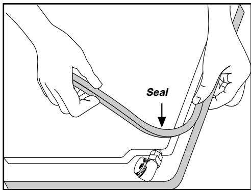
To ensure leaktightness between the frame and the worktop, stick the foam seal around the edge of the frame.
Stick on the seal supplied in the plastic bag before installing the hob:
1- Remove the pan supports, the burner covers and burner heads, noting their positions.
2- Turn the hob over and place it carefully over the opening of the cabinet so as not to damage the spark igniters.
3- Stick the foam seal supplied with the appliance in place around the outside of the frame. This seal ensures leaktightness between the glass and the worktop.
4- Replace the burner heads, burner covers and the pan supports.
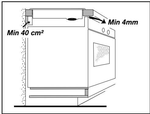
BUILDING THE HOB INTO A CABINET WITH A DOOR OR DRAWER (see diagram opposite).
Installing your hob above an oven requires a front air inlet of at least 4mm across the entire width of the hob.
It is recommended that the hob not be installed above an oven if the oven's ventilation is not frontwards.
Create an air vent in the partition to the right or left of the oven, of at least 40~cm^2

Note
The hob's heat-safety features prevent it being used while it is in pyrolysis mode.
- ELECTRICAL CONNECTION
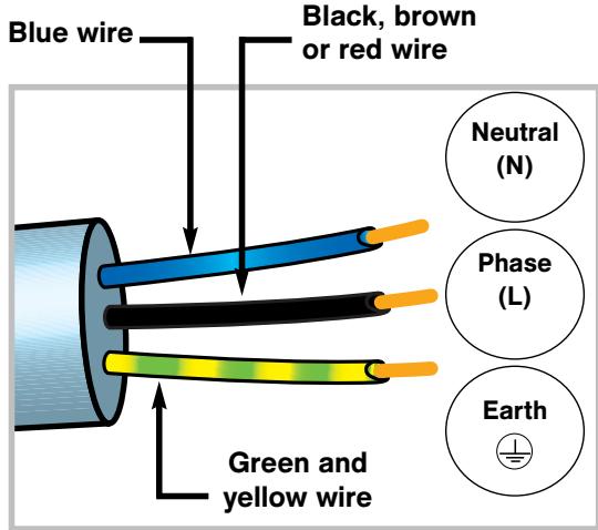
Your hob must be connected to a 220-240 V~ single phase mains supply via a standard IEC 60083 2 pole + earth electrical plug or an all-pole isolator, in compliance with the current installation regulations.
The electrical plug must remain accessible after installation.
CROSS-SECTION OF CABLE TO BE USED
| Model DTG1127* | Model DTI1127* | |
| 220-240 V~ - 50 Hz | 220-240 V~ - 50 Hz | |
| H05V2V2F - T90 | 3 conductors including 1 for earth | |
| Cross-section of conductors in mm² | 1 | 1.5 |
| Fuse | 10A | 16A |
- Connect the wires to the electricity supply, taking note of the colour of each wire (see diagram opposite).
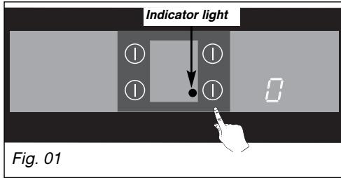
When power is first supplied to your hob, or after an extended power cut, an indicator light will be displayed on the control panel. This information will disappear after 20 seconds.
-
The safety wire (green and yellow) is connected to the appliance's earth terminal and must be connected to the mains earth terminal .
-
If the power cable is damaged, it must be replaced by the manufacturer, the After-Sales Service or a similarly qualified person, to avoid any risk.
- GAS CONNECTION
Preliminary remarks
If your hob is installed above an oven or if there is a risk of the gas supply line overheating due to the proximity of other heating elements, a rigid pipe should be used for the gas supply. If a flexible hose or tube is used (as is the case with bottled butane), it must not come into contact with any moving parts or be positioned where it might become snagged.

Note
Flexible pipes and hoses with a limited guarantee should be no more than 2 metres long and must be accessible along their entire length. They must be replaced before the end of their guarantee (indicated on the pipe). Whatever type of connection is chosen, after installing the hob use soapy water to ensure that the connection is airtight.
In France, you must use a hose or a pipe bearing the stamp NF Gaz

GAZ
The hob must be connected to the gas supply in accordance with the regulations in the country of installation.
Gas distributed via a natural gas network
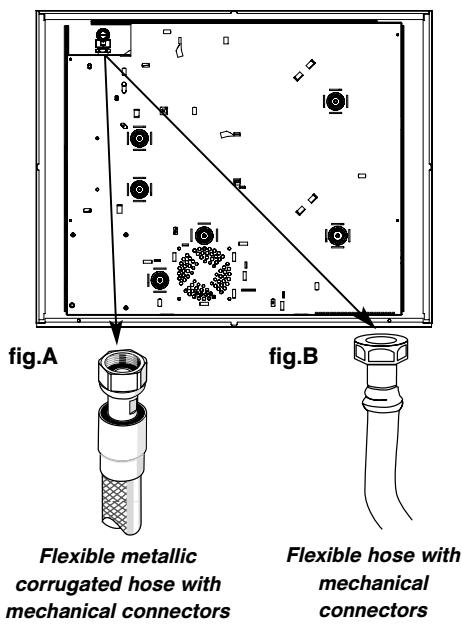
For your safety, you must choose from the three following connection options:
-
Use rigid copper pipe with screw-on mechanical connectors (G1/2 gas standard mark). Connect directly to the elbow joint fitted on the appliance.
-
Use a flexible metal corrugated hose (stainless steel) with screw-on mechanical connectors (compliant with standard NF D 36-121) with an unlimited guarantee (Fig. A).
-
Use a reinforced rubber hose with screw-on mechanical connectors (compliant with standard NF D 36-103) with a 10-year guarantee (Fig. B).
Gas supplied by tank or cylinder (butane/propane)
For your safety, you must choose from the three following connection options:
-
Use rigid copper pipe with screw-on mechanical connectors (G1/2 gas standard mark). Connect directly to the elbow joint fitted on the appliance.
-
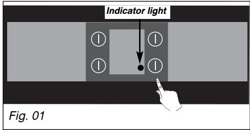
Use a flexible metal hose (stainless steel) with screw-on mechanical connectors (compliant with the NF D 36-125 standard) with an unlimited guarantee (Fig. 01).
-
Use a reinforced rubber hose with screw-on mechanical connectors (compliant with the NF D 36-112 standard) with a 10-year guarantee (Fig. 02).
In an existing system, a flexible pipe fitted with hose clips (compliant with the XP D 36-110 standard) with a 5-year guarantee may be used. In this case an adaptor must be used and a sealing washer must be inserted between the adaptor and the elbow joint (Fig. 03).
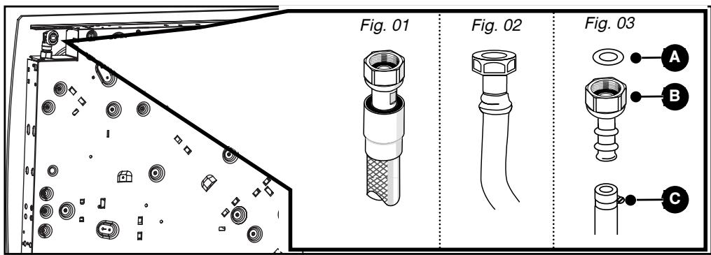
A Sealing washer (not provided)
Adaptor (not provided)
C Hose clip (not provided)

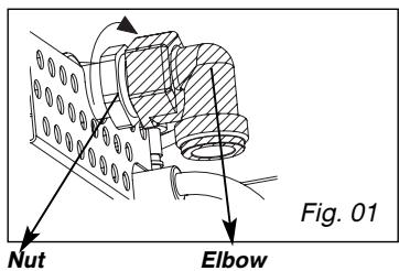
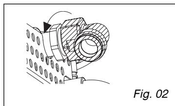
Note
When connecting your hob's gas supply, if you have to change the direction of the elbow fitted on the appliance:
① Unscrew the bolt whilst supporting the elbow (Fig. 1).
② Change the seal (supplied in the plastic bag).
③ Screw in the bolt holding the elbow in the intended position with a torque not exceeding 17 N.m (Fig. 2).
- CHANGING THE GAS SUPPLY

Note
The default settings on your hob are
for natural gas.
The injectors required for adapting the hob to a butane/propane supply can be found in the same plastic pocket as this guide.
Each time you change the gas supply, you must complete the following steps:
- Adapt the gas connection
- Change the injectors
- Connect the hob to the electrical supply
-
Check the type of gas supplied
-
Adapt the gas connector on the hob to the new gas setting. Refer to the "Connecting to the gas supply" section.
-
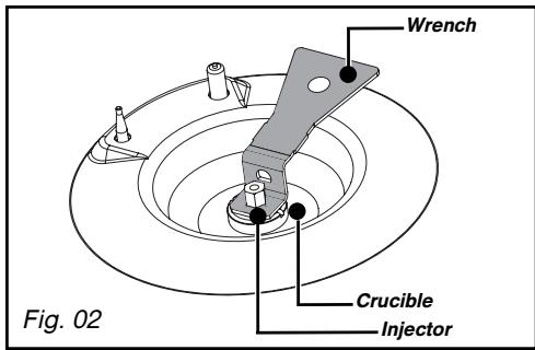
Change the injectors proceeding as follows:
-
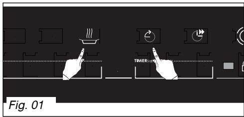
Remove the pan supports, heads and covers from all burners (Fig. 01).
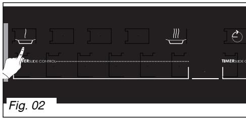
- Using the tool provided, unscrew and remove the injectors located under each crucible (Fig. 02).
- Replace with the new gas injectors; refer to the injector positioning markers and the gas settings table at the end of this chapter. The new injectors should be fitted as follows:
-First,manuallytightenasfaraspossible. - Then fully engage the key onto the injector.
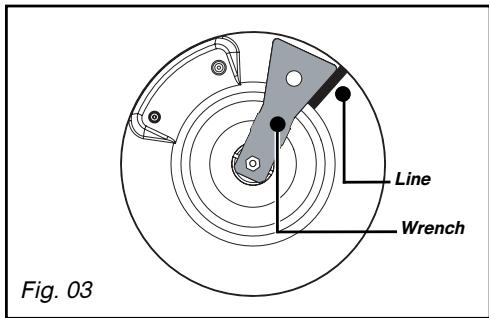
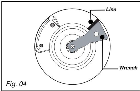
- Draw a line on the burner plate using a pencil, as shown (Fig. 03).
Turn the wrench clockwise until the line appears on the opposite side of the key (Fig. 04).

Note
Exceeding this limit may damage the object.
-Replace the burner heads, burner covers and pan supports on the hob.

Tip
Each time you change the gas supply, the box corresponding to the new gas on the label found in the plastic bag.
See "Connecting to gas the supply".
- Electrical connection:
- Connect the power cable from your hob to your single-phase mains supply (220-240 V~). Refer to the section "Connecting to the electricity supply".
- Check the type of gas supplied
-Select touch control Whilst keeping your finger on this control, press touch control (Fig.01).
An audible signal confirms your selection.
Within the following 5 seconds,
- Press touch control twice (Fig. 02).
An audible signal confirms your selection.
The back right zone display indicates the type of gas selected.
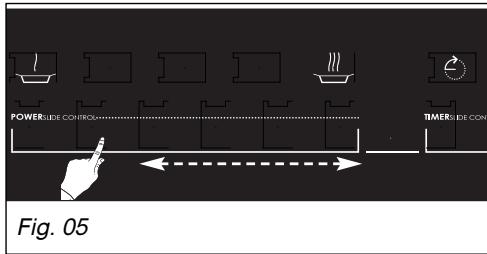
-To change the gas supply type, use the "power slider", sliding your finger to the left or to the right.
The gas supply type is confirmed automatically after 5 seconds. (Fig. 05).
YOUR HOB IS READY FOR USE.
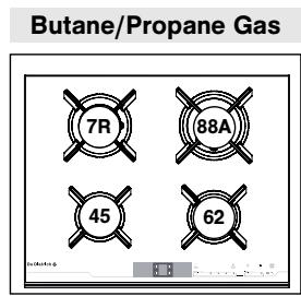
Gas settings
| FR-CH ES-IT PT | FR-CH ES-IT PT | FR-CH ES-IT PT-CY EE - PL LT | FR | |
| Appliance intended to be installed in: | Butane | Propane | Natural Gas | Natural Gas |
| FR ............cat: II2E+3+ | G30 | G31 | G20 | G25 |
| CH - ES - IT - PT .......cat: II2H3+ | ||||
| CY - EE - PL .......cat: II2H3B/P | ||||
| LT ............cat: I2H | ||||
| Hourly flow rate below: | 28-30 mbar | 37mbar | 20 mbar | 25 mbar |
| 25 mbar at 15°C under 1013 mbar | ||||
| FAST BURNER | ||||
| Marking on injector | 7R | 7R | 1R | 1R |
| Nominal heat release rate (kW) | 2.15 | 2.15 | 2.25 | 2.25 |
| Reduced heat release rate (kW) | 0.830 | 0.870 | 0.870 | |
| Hourly rate (g/h) | 156 | 154 | ||
| Hourly rate (l/h) | 214 | 249 | ||
| HIGH SPEED BURNER | ||||
| Marking on injector | 88A | 88A | 137 | 137 |
| Nominal heat release rate (kW) | 3.15 | 3.15 | 3.10 | 3.10 |
| Reduced heat release rate (kW) | 0.830 | 0.870 | 0.870 | |
| Hourly rate (g/h) | 229 | 225 | ||
| Hourly rate (l/h) | 295 | 343 | ||
| SEMI-FAST BURNER | ||||
| Marking on injector | 62 | 62 | 94 | 94 |
| Nominal heat release rate (kW) | 1.50 | 1.50 | 1.50 | 1.50 |
| Reduced heat release rate (kW) | 0.620 | 0.615 | 0.615 | |
| Hourly rate (g/h) | 109 | 107 | ||
| Hourly rate (l/h) | 143 | 166 | ||
| AUXILIARY BURNER | ||||
| Marking on injector | 45 | 45 | 63 | 63 |
| Nominal heat release rate (kW) | 0.70 | 0.70 | 0.85 | 0.85 |
| Reduced heat release rate (kW) | 0.300 | 0.350 | 0.350 | |
| Hourly rate (g/h) | 51 | 50 | ||
| Hourly rate (l/h) | 81 | 94 | ||
| HOB WITH 4 GAS BURNERS AND HIGH SPEED BURNER | ||||
| Total heat release rate (kW) | 7.50 | 7.50 | 7.70 | 7.70 |
| Maximum rate (g/h) | 545 | 536 | ||
| 733 | 852 | |||
| HOB WITH 2 GAS BURNERS AND 2 INDUCTION ZONES | ||||
| Total heat release rate (kW) | 4.65 | 4.65 | 4.60 | 4.60 |
| Maximum rate (g/h) | 338 | 332 | ||
| 438 | 509 |
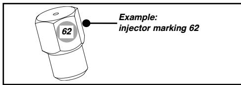
- Identifying the injectors
The adjacent table shows where the injectors are positioned on your appliance according to the type of gas used.
The number is marked on each injector.

ELECTRICITY
| - Power supply: | 220-240 V~ - 50 Hz |
| - Total input power: | 3100 W (1) |
| - Hob dimensions: | |
| - Width | 650 mm |
| - Depth | 520 mm |
| - Weight | 11.4 kg |
| - Dimensions of unit: | |
| - Width | 549 mm |
| - Height | 59 mm |
| - Depth | 470 mm |
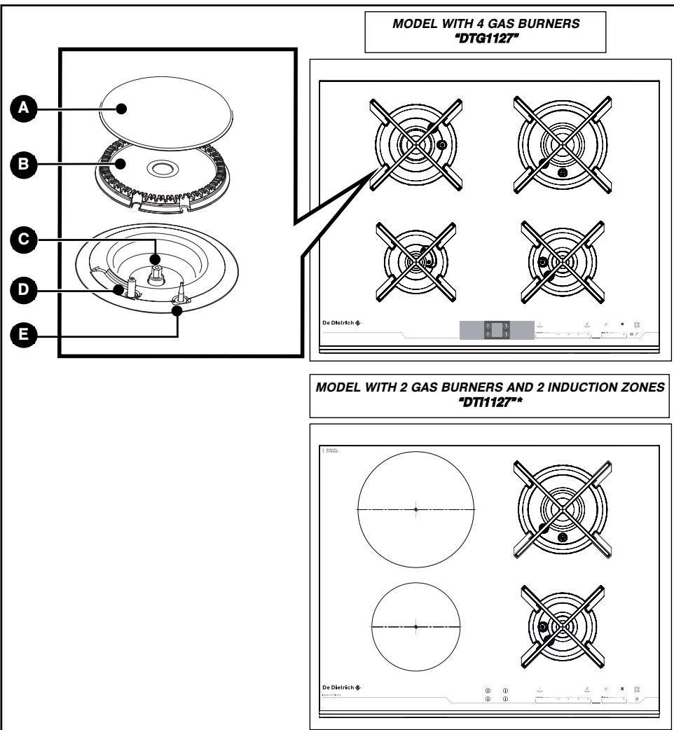
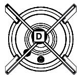
DESCRIPTION OF YOUR HOB
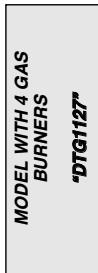
MODEL WITH 4 GAS BURNERS "DTG1127"
De Dietrich

MODEL WITH 2 GAS BURNERS AND 2 INDUCTION ZONES "DT1127"
1

De Dietrich
①
六
点
。
8
1
A Front left burner. auxiliary burner 0.85kW^
B Front right burner semi-fast burner 1.50kW^
Rear left burner. fast burner 2.25 kW*
Rear right burner . high speed burner 3.10 kW*
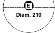
Induction zone diameter 210 = 3100W
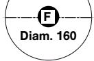
Induction zone diameter 160 = 2000 W
*Power obtained with natural gas G20
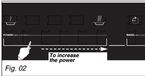
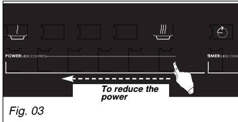
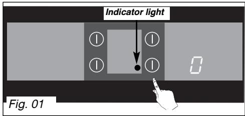
- USING A COOKING ZONE
- Place your cookware on the cooking zone.
- Press the start/stop touch control for the cooking zone concerned.
You selection is confirmed by a beep and a flashing 0 indication (Fig. 01).
The indicator for the selected zone lights up.
- Setting the power:
either by sliding your finger on the power slider from left to right to increase power (Fig. 02).
You can decrease the power by sliding your finger from right to left (Fig. 03).

- Moving your finger slowly allows you to adjust the power more accurately than in you move it quickly.
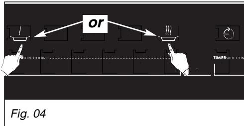
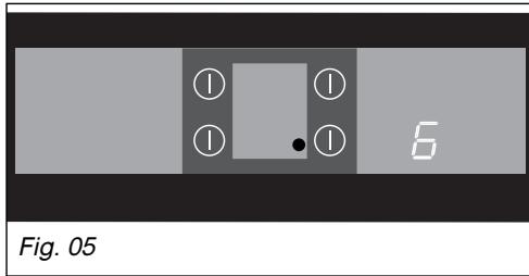
Or by pressing one of the preset power touch controls: or (Fig. 04).

Power 3 by default

Power 6 by default (Fig. 05).

- Both these touch controls can be managed by the user. See chapter: "Changing preset power touch controls".
- Switching off a cooking zone:
- Press and hold the selection touch control for the cooking zone concerned (Fig. 06).
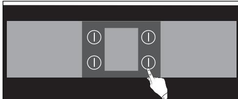
Fig. 06
-Residual heat indicator:
After use, the cooking zone may remain hot for a few minutes.
An “ H ” is displayed during this period. Do not touch the zones concerned during this time.

- The flames of the gas burner are
smaller near the support to protect the enamel.

Note
- If the flames go out accidentally
(e.g. due to a gust of air), your hob is equipped with an automatic relighting system. This is limited to 2 re-lightings separated by 10 seconds.
- The minimum temperature for use is 10^ to ensure optimal functioning of the tap.
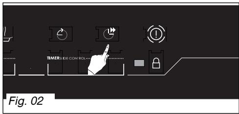
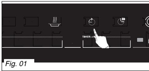
- USING THE TIMER DURING COOKING
The timer applies to the zone selected (indicator lit) (Fig. 01).
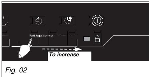
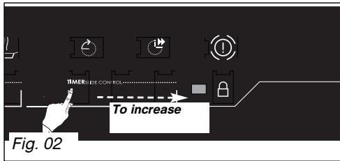
- You increase the time by sliding your finger on the timer slider from left to right (Fig. 02).
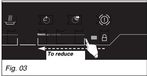
- You can reduce the time by sliding from right to left (Fig. 03).
- Selecting the "RECOMMENDED" timer:
you can also press successively on the touch control to set the timer (Fig. 04).
When the cooking is finished, ±b0 is displayed and a beep sounds. Press on the selector touch control for the zone to clear this information (Fig. 05).

You can allocate a time to each
zone.
- You can stop the timer by pressing and holding the "RECOMMENDED timer" touch control. The corresponding timer display goes out and the zone continues to operate.
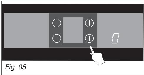
- USING THE INDEPENDENT TIMER
This function allows you to time an event, without cooking.
-Select an unused cooking zone. 0 and the indicator for the selected zone are displayed (Fig. 01).
- Set the time either using the timer slider or the "RECOMMENDED" timer touch control. A flashes with the time selected (Fig. 02).
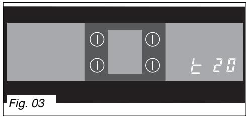
Once set, "t" becomes fixed and the countdown begins.
(Fig. 03) shows a time of 20 minutes has been selected.
-You can stop the timer by selecting the corresponding cooking zone ①

-
In this way you can activate up to dependent timers (with the hob turned
-
During the final minute, the countdown is displayed in seconds.
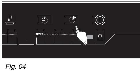
- USING THE "ELAPSED TIME" FUNCTION
This function displays the time elapsed since the last time the power setting was adjusted on a given burner.
-To use this function, press the button (Fig. 01).
The time elapsed appears in the display.
If you want your cooking to finish within a defined time.
- Press touch control then, within 5 seconds, slide your finger on the timer slider to increase the cooking time to the value you want (Fig. 02).
The time display becomes fixed for 3 seconds, then the remaining cooking time will appear.
A beep will confirm your choice.
This function can be used with or without the timer.

- If a time is displayed on the timer, this cannot be modified for 5 seconds after a touch control has been pressed. For these 5 seconds have elapsed, you can notify your cooking time.
ADJUSTING THE POWER PRESETS
This function allows you to display and change the power levels defined in the presets.
- Turn off the cooking zones on your hob.
- Select the touch control or to be changed by pressing and holding (Fig. 01).
The current preset power level is displayed.
- Set the new power level by sliding your finger to the left or right on the power slider as desired (Fig. 02).
You can select between 1 and 5
You can select between 6 and 9
A beep will confirm your action after a few moments.
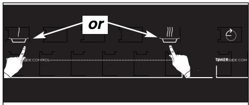
Fig. 01
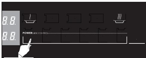
Fig. 02
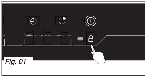
- CHILD SAFETY
This function allows you to lock your hob when it is shut off or when it is cooking.
To lock:
- Press and hold (Fig. 01).
A beep sounds and the indicator lights up. The indicator will go out automatically after a few moments.
To unlock:
- Press and hold (Fig. 01).
A double beep sounds and the indicator goes out.
- CLEAN LOCK
This function allows you to temporarily lock your hob while cleaning.
To activate CLEAN LOCK:
- Your cooking hob must be turned off.
-Briefly press touch control (Fig. 01).
You will hear a beep and the indicator will start flashing.
- After a preset time, the lock will automatically disengage. A double beep sounds and the indicator goes out.

In "locked" mode, any action will produce a key symbol on the days.
You must unlock your hob before you can use it again.
- If you activate the lock while cooking, turning off the zones will take priority over the lock.
OPERATING SAFETY
GENERAL STOP
- You can stop any gas burners currently operating by pressing touch control ① . This action cancels locking if this had been programmed.
- TEMPERATURE LIMITER (MODEL DTI1127*)
Each cooking zone is equipped with a safety sensor that constantly monitors the temperature of the bottom of the cookware. If you leave empty cookware on a zone which is turned on, the power will be automatically limited to prevent damage to the cookware or hob.
PROTECTION AGAINST OVERFLOWS
In case of overflow, or of a metallic object or wet cloth placed on the control buttons, the hob turns itself off, the displays light up and a beep sounds. Clean the hob or remove the object, then begin cooking again.
- AUTO-STOP SYSTEM
- Should you forget that cooking is in progress, this safety function will automatically turn the hob off after a predefined time (between 1 and 8 hours depending on the power setting). "AS" is displayed and a beep sounds for about 2 minutes. Press on the main selector touch control to delete this information. A beep will confirm your setting.
"SMALL OBJECTS SAFETY DEVICE (MODEL DT1127*)
- If you place a small object on the area (a ring, a fork, etc), the hob will detect it and not deliver any power. The power display will flash. Note: however, several small objects on the cooking zone at the same time could be identified as cookware. The hob will therefore deliver power in this case.
Note - It is recommended to avoid placing metal objects such as knives, forks, spoons and lids on the cooking surface, as they may heat up.
COOKWARE SUITABLE FOR GAS BURNERS
- Which burner should you use for your pans?
| Pan diameter | Pan diameter | Use |
| 18 to 28 cm | Super fast | Frying - Boiling |
| 16 to 22 cm | High-speed | Searing foods |
| 12 to 20 cm | Semi-fast | Sauces - Reheating |
| 8 to 14 cm | Auxiliary | Gentle simmer |
- Adjust the ring of flames so that it does not extend beyond the edge of the pan (Fig. 01).
- Do not use cookware with a concave or convex bottom (Fig. 02).
- Do not leave empty cookware over an ignited gas burner.
- Do not use cookware that partially covers the control panel.
- Do not use heat regulators, toasters, griddle pans or stewpots with feet which sit on or touch the glass top.

-
Ensure that all natural ventilation is in or install a mechanical ventilation ce (mechanical ventilation hood).
-
Intensive, prolonged use of the appliance may require additional ventilation, for example by opening a window, or more effective ventilation, by increasing the power of any mechanical ventilation device (a minimum air flow of 2m^3/hr per kW of gas power is required).
Example for this hob:
- total power: 0.85 + 1.5 + 2.25 + 3.1 = 7.7 kW 7.7 kW × 2 = 15.4 m^3 / hr minimum flow .
CORRECT
INCORRECT
Fig. 01
CONVEX
CONCAVE
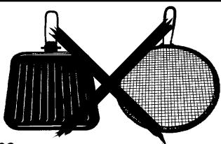
Fig. 02
Fig. 03
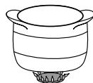
- INDUCTION-SAFE COOKWARE
- Which cookware is the most suitable?
You probably already have pans that are suitable for an induction hob.
Enamelled steel pans with or without non-stick coating: casserole dishes, deep fryers, saucepans or griddle pans.
Cast-iron pans: so as not to scratch the vitroceramic surface, avoid sliding pans over the hob surface, or choose a pan with an enamel-coated base.
- Induction-safe stainless steel pans: most stainless steel pans are suitable for induction cooking (saucepans, casserole dishes, frying pans and deep fryers).
Aluminium pans with special bases: choose pans with flat, thick bottoms, which provide a more even cooking (the heat is distributed better).
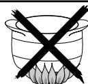
- An "INDUCTION CLASS" logo
Only glass, terra cotta, aluminium without a special finish on the bottom, copper and some non-magnetic stainless steels do not work with induction cooking. We recommend that you select cookware with a thick, flat bottom.
When you buy your cookware, make sure that this logo is on the package; it assures you that it is compatible with induction cooking.

To help you choose, a list of utensils is provided in this booklet.
- Residual heat indicator
After intensive use, the cooking area may remain hot for a few minutes.
A H will be displayed. Do not touch the zones concerned during this time.
What type of pans can I use?
GLASS, CERAMIC, EARTHENWARE, ALUMINIUM WITHOUT A SPECIAL BASE, COPPER AND CERTAIN NON-MAGNETIC STAINLESS STEEL COOKWARE.
- The "cookware" test
Thanks to its cutting edge technology, the hob is able to recognise most types of cookware. Place your pan on a hotplate, for example at power level 4, if the display is normal, your pan is OK to use; if it flashes, your pan is not suitable for use on an induction hob. Even pans without a completely flat bottom can be used, as long as the bottom isn't too out of shape.
Automatic-stop
Automatic stop is a safety feature of your hob. It is automatically activated if you forget to turn off the cooker:
| Power level used | The cooking plate switches off automat-ically after: |
| Positioned: between 1.......7 between 8.......11 above 12 | 8 hours 2 hours 1 hour |
AS is shown on the display for the hotplate concerned, and a beep sounds for about 2 minutes. AS will continue to be displayed until you press one of the buttons for the hotplate. A double beep will sound to confirm that a button has been pressed.
- INDUCTION-SAFE COOKWARE (continued)
- Precautions for use
-
When using non-stick pans (such as Teflon) and little or no butter or oil, briefly preheat on position 9 or position 10. Never use position 11 or 12, as this may damage your pan.
-
Never heat sealed cans as they may explode (this applies to any type of cooking).
-
It is recommended to avoid placing metal objects such as knives, forks, spoons and lids on the cooking surface, as they may heat up.
Note Obiec
should never be placed on the hob.
When cooking, never use aluminium foil and never place products wrapped in aluminium directly on the hob. The aluminium would melt and would permanently damage your appliance.
- "Electronic" safety feature
If the temperature in the electronic circuits becomes too high, the safety feature will automatically reduce the power delivered by the hob.
- "Empty saucepan" safety feature
Each heating zone is equipped with a safety device that constantly detects the temperature of the heating zone. Thus there is no risk of overheating caused by empty pans.
Use the correct hotplate for the pan (depending on the model)
Multiple cookware
This 23 cm cooking zone:
- Automatically adjusts to the pan.
- Delivers the optimum power level.
- Ensures excellent distribution of heat.
- Provides an even cooking temperature, so that whether you are cooking large pancakes, a large fish, etc., or large amounts of small foodstuffs, they will be cooked evenly.
0 23 cm 012.....26cm
Multiple services
018cm 012.....22cm
021cm 018.....24cm
Small cookware
0 16 cm 0 10.....18cm
Gentle cooking (saues,creams,etc.) Preparation of small amounts or individual portions.

Note
- If an oven is located below your hob (see "Tips for flush mounting"), the hob's thermal safety devices will make it impossible to use the hob and your oven's pyrolysis function at the same time.
When using the induction hob, do not place objects that can be magnetised on the glass worktop (e.g. credit cards, cassettes, etc.)
Special warning for people with active implants (pacemakers, insulin pumps, etc.): your induction hob generates a magnetic field in the immediate area. We therefore recommend that you contact the manufacturer of your active implant to determine any possible incompatibilities.
It will be easier to maintain your hob if you clean it before it has completely cooled down. However, never clean your appliance while it is in operation. Set all the controls to zero.
WHAT TO DO?
PRODUCTS/ACCESS ORIES TO USE
Maintaining spark igniters and injectors
Small, hard-bristled brush.
If the spark ignitors become clogged, clean them using a small, stiff-bristled brush (nonmetallic bristles).
The gas injector is located in the depression in the centre of the burner. Be careful not to obstruct it during cleaning, as this will undermine the performance of your hob. Use a safety pin to unblock the injector if necessary.
Maintaining pan supports and gas burners
For tough stains, use a non-abrasive cream, then rinse with clean water. Carefully wipe each part of the burner before using your hob again.
Gentle scouring cream.
Cleaning sponge.
Maintaining the glass top
Clean with warm water and then wipe. For tough stains, use special vitroceramic glass cleaning products.
Cleaning sponge.
Special vitroceramic glass products (e.g.:
Maintaining the induction zones
Clean with warm water and then wipe. If necessary finish with the scouring side of a sponge then wipe. For tough stains, use special glass vitroceramic products (see examples opposite)
Cleaning sponge.
Special glass vitroceramic products (you can obtain cleaning products from your after-sales service department).

- We recommend cleaning the hob fittings by hand rather than in a dishwasher.
- Do not use an abrasive sponge to clean your hob.
- Do not use a steam cleaner.

- In the event that a crack becomes visible in the glass worktop, immediately unplug it to the appliance to avoid an electric shock and contact the After-Sales Service Department.
You have a doubt about whether your hob is working properly ......... this does not necessarily mean there is a problem with your hob. In all cases, check the following:
| ERROR CODE | WHAT IS HAPPENING? | WHAT TO DO |
| ▲2 beeps are heard then F1 - F2 - F3 or F4... is displayed on the timer followed by numbers then the display is cleared. | This is the procedure for connecting your hob to the electric power. If you press on the overall stop button ①; this is normal. | Wait for a few seconds for the display to go out. Your hob is ready to use. |
| ▲ are not able to operate any of the controls and the displays show nothing. | Electricity power out. Your burner does not light. | Check that you have electric power. If you have power and the fault persists, call your After-Sales Service.. |
| ▲ displays E4 and one of the indicator lights for the faulty burner comes on for a few seconds then goes off. | Your burner does not light. | Check that the gas is turned on and that the burners are correctly assembled. Check that the injectors correspond to the gas being used (see table of technical characteristics). Check that the corresponding burner is sparking properly. After carrying out all these checks, turn it on again by pressing %1. |
| ▲ displays D2. | The cooking zones are not working. The gas changing switch is in the wrong position. | Press the position of the gas changing switch and press on the overall gas stop button to erase the fault Light again. If the fault continues contact After Sales Service. |
| ▲ displays E2 and one of the ring's indicator lights is flashing. | The affected burner cannot be used. However, you can use the other burner. | Press the overall gas stop button to clear the fault. If the fault continues contact After Sales Service. |
| ▲ displays E7: one of the indicators lights up to say the burner is faulty. | You have a flame or a hot item on the safety unit (thermocouple). | Press the overall gas stop button to clear the fault. If the fault continues contact the After Sales Service. |
| ▲ displays EE: | The hob has 2 faults. | Press the overall gas stop button to clear the fault. If the fault continues contact the After Sales Service. |
You have a doubt about whether your hob is working properly ......... this does not necessarily mean there is a problem with your hob. In all cases, check the following:
| ERROR CODE | WHAT IS HAPPENING? | WHAT TO DO |
| ▲ B B displays EC and one of the ring's indicator lights is on. | The affected burner cannot be used. However, you can use the other burner. | ✓ Using the hob in an environment where the temperature is below 10°C may temporarily prevent the hob from working. ✓ Press the overall gas stop button to clear the fault. ✓ If the fault continues contact After Sales Service. |
| ▲ B B displays E1 or a series of - | The electronic circuits are hot. | ✓ Check the installation. ✓ Press the overall gas stop button to erase the E1 display. ✓ If the fault continues contact After Sales Service. |
| ▲ B B displays a E-d -C type fault not mentioned above. | The rings are not working. | ✓ Press the overall gas stop button to clear the fault. ✓ If the fault continues contact After Sales Service. |
You have a doubt about whether your hob is working properly ......... this does not necessarily mean there is a problem with your hob. In all cases, check the following:
WHAT TO DO
ERROR
CODE
Lighting the burners:
No sparks appear when the touch controls are pressed.
When lighting a burner, sparks appear on all the burners at the same time.
This is normal. The ignition function is centralised and controls all burners at the same time.
- Check that the gas inlet pipe is not pinched.
- Check that the length of the gas inlet pipe is less than 2 metres.
Check that the gas inlet is open.
If you use gas from a cylinder or tank, check that it is not empty.
If you have just installed the hob or changed the gas cylinder, repeat the operations for lighting the burners several times until gas arrives at the burners.
Check that the injector is not clogged; if it is, unclog it with a safety pin.
Light your burner before placing your saucepan on it.
In reduced heat mode, the burner goes out or the flames remain high.
The flames are irregular or uneven.
Avoid strong air currents in the room.
Check that the correct injectors have been fitted for the type of gas being used (see the markings on the injectors in the "Gas settings").
section).
Reminder: The default settings on the hob are for a mains gas supply (natural gas).
Check that the
positioned (see the Changing the gas supply section).
Check the cleanliness of the burners and injectors under the burners, the assembly of the burners, etc.
Check that there is enough gas in the cylinder.
There are sparks, but the burner does not light.
| PREPARATIONS | TIME | HIGH SPEED | FAST | SEMI-FAST | AUXILIARY | |
| SOUPS | Bouillons Thick soups | 8-10 minutes | X | X | ||
| FISH | Court bouillon Barbecue | 8-10 minutes | X | X | ||
| 8-10 minutes | X | |||||
| SAUCES | Hollmandaise, béarnaise Béchamel, aurore | 10 minutes | X | X | ||
| X | X | |||||
| VEGETABLES | Chicory, spinach Cooked peas Provençal tomatoes Fried potatoes Pasta | 25-30 minutes | X | X | ||
| 15-20 minutes | X | X | ||||
| X | X | |||||
| X | ||||||
| MEAT | Steak Blanquette, Osso-bucco Sautéed poultry breasts Barbecue (cast iron grill) | 90 minutes | X | |||
| 10-12 minutes | X | |||||
| 10 minutes | X | |||||
| FRYING | French fries Fritters | X | ||||
| X | ||||||
| DESSERTS | Rice pudding Fruit compote Pancakes Chocolate Custard | 25 minutes | X | X | X | X |
| 3-4 minutes | X | |||||
| 3-4 minutes | X | |||||
| 10 minutes | X | |||||
| PREPARING | FRYING BRANDING TO THE BOIL | COOKING/BROWNING RETURNING TO THE BOIL BOILING LIGHT BROTHS | COOKING/SIMMERING | KEEP WARM | ||||||||
| COOKING ZONE POWER LEVEL | 12 | 11 | 9 | 8 | 7 | 6 | 5 | 4 | 3 | 2 | 1 | |
| The maximum power levels should be used only for frying and bringing rapidity to the boil. | CLEAR SOUPS | BROTHS THICK SOUPS | ||||||||||
| FISH | COURT-BOULLON FROZEN FOODS | |||||||||||
| SAUCES | THICK, FLOUR-BASED WITH BUTTER AND EGGS (BÉARNAISE, HOLLANDAISE) | |||||||||||
| VEGETABLES | CHICORY, SPINACH DRYVEGETABLES BOILED POTATOES BROWNED POTATOES SAUTEED POTATOES DEFROSTING OF VEGETABLES | |||||||||||
| MEAT | THIN CUTS OF MEAT PAN-FRIED STEAKS GRILLED MEAT (CAST IRON GRILL) | |||||||||||
| FRIED FOODS | FROZEN CHIPS FRESH CHIPS | |||||||||||
| OTHER | PRESSURE COOKER COMPOTES PANCAKES CUSTARD MELTED CHOCOLATE JAMS MILK FRIED EGGS PASTA JARS OF BABY FOOD (BAIN MARIE) RAGOÜTS CREOLE RICE RICE PUDDING | (FROM WHEN IT STARTS TO WHISTLE) | ||||||||||
- SERVICE CALLS
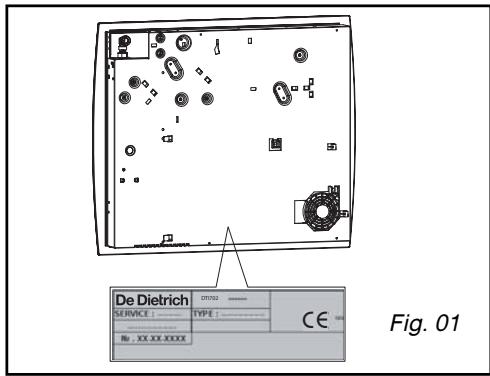
Any repairs to your appliance must be carried out by a qualified professional authorised to work on this brand. When you call, state your appliance's complete reference information (model, type, serial number). This information appears on the manufacturer's nameplate (Fig. 01).
ORIGINAL PARTS
During any servicing, request the use of genuine replacement parts only.

FagorBrandt SAS, tenant-manager - SAS with share capital of 20 000 000 euros RCS Nanterre 440 303 196.
Volte a colocar as grelhas de suporte dos acessórios, as tampas e as cabecas dos bicos.
-Volte a colocar as grelhas de所提供 de dos acessórios, as tampas e as cabecas dos bicos.

Conselho
Cada vez que Mudar de gás, marque a casa que corresponde ao novo tipo de gás na etiqueta existente na Bolsa.

- - RELATIONS CONSOMMATEURS
- 1/USERNOTICES
- 2/ INSTALLING YOUR APPLIANCE
- 3/ USING YOUR APPLIANCE
- 4/ DAILY CARE OF YOUR APPLIANCE 66
- 5/ SMALL FAULTS AND PROBLEMS 67
- 6/ COOKING CHART FOR GAS BURNERS 70
- 7/ COOKING CHART FOR INDUCTION ZONES 71
- 8/ AFTER-SALES SERVICE AND CUSTOMER RELATIONS
- Important
- SAFETY GUIDELINES
- Note
- CARING FOR THE ENVIRONMENT
- THE INDUCTION PRINCIPLE
- DESCRIPTION OF THE HOB
- LAYOUT OF THE CONTROL PANEL
- - SELECTOR TOUCH CONTROLS
- For a selected zone
- ADJUSTMENT TOUCH CONTROLS
- TIPS FOR FLUSH MOUNTING
- Example:
- - ELECTRICAL CONNECTION
- - GAS CONNECTION
- Preliminary remarks
- Gas distributed via a natural gas network
- Gas supplied by tank or cylinder (butane/propane)
- - CHANGING THE GAS SUPPLY
- Exceeding this limit may damage the object.
- Tip
- - Electrical connection:
- - Check the type of gas supplied
- Gas settings
- - Identifying the injectors
- DESCRIPTION OF YOUR HOB
- - USING A COOKING ZONE
- - Setting the power:
- - Switching off a cooking zone:
- -Residual heat indicator:
- - USING THE TIMER DURING COOKING
- - Selecting the "RECOMMENDED" timer:
- You can allocate a time to each
- zone.
- - USING THE INDEPENDENT TIMER
- - USING THE "ELAPSED TIME" FUNCTION
- ADJUSTING THE POWER PRESETS
- - CHILD SAFETY
- To lock:
- To unlock:
- - CLEAN LOCK
- To activate CLEAN LOCK:
- OPERATING SAFETY
- GENERAL STOP
- - TEMPERATURE LIMITER (MODEL DTI1127*)
- PROTECTION AGAINST OVERFLOWS
- - AUTO-STOP SYSTEM
- "SMALL OBJECTS SAFETY DEVICE (MODEL DT1127*)
- COOKWARE SUITABLE FOR GAS BURNERS
- - INDUCTION-SAFE COOKWARE
- - Which cookware is the most suitable?
- - An "INDUCTION CLASS" logo
- - Residual heat indicator
- - INDUCTION-SAFE COOKWARE (continued)
- - Precautions for use
- Note Obiec
- - "Electronic" safety feature
- - "Empty saucepan" safety feature
- Use the correct hotplate for the pan (depending on the model)
- Multiple cookware
- This 23 cm cooking zone:
- Multiple services
- Small cookware
- WHAT TO DO?
- PRODUCTS/ACCESS ORIES TO USE
- WHAT TO DO
- ERROR
- CODE
- - SERVICE CALLS
- ORIGINAL PARTS
- Conselho
Brand : DE DIETRICH
Model : DTI 1127 X
Category : Hob