
SA10 - Receiver ARCAM - Free user manual and instructions
Find the device manual for free SA10 ARCAM in PDF.
| Product Type | Stereo Integrated Amplifier / Receiver |
| Brand | Arcam |
| Model | SA10 |
| Dimensions (W x H x D) | 433 x 97 x 310 mm |
| Net Weight | 8.4 kg |
| Power Supply | 110-120 V or 220-240 V, 50-60 Hz |
| Max Power Consumption | 350 W |
| Output Power (8 Ω, 20 Hz - 20 kHz, 0.5% THD) | 50 W per channel |
| Output Power (4 Ω, 1 kHz, 0.5% THD) | 85 W per channel |
| Harmonic Distortion (80% power, 8 Ω, 1 kHz) | 0.003% |
| Analog Inputs | Phono (MM), 4 x line (AUX, STB, PVR, CD, BD, AV) |
| Digital Inputs | 2 x coaxial, 1 x optical |
| Outputs | Preamp (PRE OUT), headphone (3.5 mm), speakers (2 channels) |
| DAC | ESS9018K2M |
| Signal-to-Noise Ratio (line input) | 106 dB (A-weighted) |
| Signal-to-Noise Ratio (phono input) | 80 dB (A-weighted) |
| Network Connectivity | Ethernet (RJ45), RS232, USB (firmware update) |
| Remote Control | Yes (AAA batteries included) |
| Auto Standby | Yes, adjustable from 30 min to 4 h or disabled |
| Warranty | 5 years (parts and labor) subject to conditions |
| Included Accessories | Power cable, remote control, 2 AAA batteries |
Frequently Asked Questions - SA10 ARCAM
User questions about SA10 ARCAM
0 question about this device. Answer the ones you know or ask your own.
Ask a new question about this device
Download the instructions for your Receiver in PDF format for free! Find your manual SA10 - ARCAM and take your electronic device back in hand. On this page are published all the documents necessary for the use of your device. SA10 by ARCAM.
USER MANUAL SA10 ARCAM
Important Safety Instructions
- Read these instructions.
- Keep these instructions.
- Heed all warnings
- Follow all instructions.
- Do not use this apparatus near water.
- Clean only with dry cloth
- Do not block any ventilation openings. Install in accordance with the manufacturer's instructions.
- Do not install any heat sources such as radiators, heat registers, swires, or other apparatus (relating amplifiers) that produce heat.
- Do not defeat the safety purpose of the polarized or grounding type plug.
A polarized plug has two blades with one wider than the other. A grounding type plug has two blades and a third grounding prong. The wide blade or the third prong are provided for your safety. If the provided plug does not fit into your outlet, consult an electrician for replacement of the obsolete outlet.
- Project the power card from being walked on or pinched particularly at plugs, convenience receptacles, and the point where they exit from the apparatus.
- Only use attachments/accessories specified by the manufacturer.
- Use only with the cart, stencs, tripped brackets, or table specified by the manufacturer, or sold with the apparatus.
When a cart is used, use caution when moving the cart/aparatus combination to avoid injury from topover.

-
Unolug this apparatus during lightning storms or when unused for long periods of time.
-
Referral servicing to qualified service personnel
Servicing is required when the apparatus has been damaged in any way, such as power-supply cord or plug is damaged, liquid has been spilled or objects have fallen into the apparatus, the apparatus has been exposed to rain or moisture, does not operate normally, or has been dropped.
- Object or liquid entry
WARNING - Take care that objects do not fill and liquids are not spilled into the enclosure through any openings. The equipment shall not be exposed to dripping or splashing. Liquid filled objects such as vases should not be placed on the equipment.
- Climate
The equipment has been designed for use in moderate climatics and in domestic situations.
17.Cleaning
Unplug the unit from the mains supply before clearing.
The case should normally only require a wrist with a soft, Int-free cloth. Do not use chemical solvents for cleaning.
We do not advise the use of furniture cleaning sprays or polishes as they can cause permanent white marks.
18.Power sources
Only correct the equipment in a power supply of the type described in the operating instructions or as marked on the equipment.
The primary method of isolating the equipment from the mains supply is to remove the mains plug. The equipment must be installed in a manner that makes disconnection possible.
- Abnormal smell
If an abnormal smell or smoke is detected from the equipment, turn the power off immediately and unplag the equipment from the wall out of Contact, your dealer and do not reconnect the equipment.
- Damage requiring service
The equipment should be serviced by qualified service personnel when:
A. The power-supply cord or the plug has been damaged, or
3. Objects have fallen, or liquid has spilled into the equipment, or
C The equipment has been exposed to rain, or
D. The equipment does not appear to operate normally or exhibits a marked change in performance.
The equipment has been dropped or the enclosures damaged.
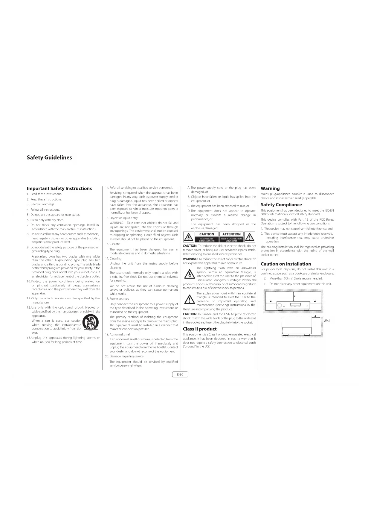
CAUTION: To reduce the risk of electric shock, do not remove cover (or back), No user serviceable parts inside. Refer servicing to qualified service personnel.
WARNING: To reduce the risk of fire or electric shock, do not expose this apparatus to rain or moisture.
The lightning flash with an arrowhead symbol within an equilateral triangle, is intended to alert the user to the presence of uninsulated dangerous voltage within the product's enclosure that may be of sufficient magnitude to constitute a risk of electric shock to persons.
The explanation point within an equational triangle is intended to alert the user to the presence of important operating and maintenance (servicing) instructions in the literature accompanying the product.
CAUTION: In Canada and the USA, to prevent electric shock, match the wide blade of the plug to the wide slot in the socket and insert the plug fully into the socket.
Class II product
This equipment is a Class II or double insulated electrical appliance. It has been designed in such a way that it does not require a safety connection to electrical earth ("ground" in the U.S.).
Warning
Mains plug/appliance coupler is used to disconnect device and it shall remain readily operable.
Safety Compliance
Tn's equipment has been designed to meet the IEC/EN 60065 international electrical safety standard.
This device comfers with Part. 15 of the FCC Rules. Operation is subject to the following two conditions:
- This device may not cause harmful interference, and
- This device must accept any interference received, including interference that may cause undesired operation.
The building installation shall be regarded as providing protection in accordance with the rating of the wall socket outlet.
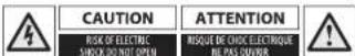
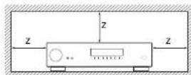
Caution on installation
or proper heat dispersal, do not install this unit in a confined space, such as a bookcase or similar enclosure.
More than 0.3m (12in) is recommended.
Do not place any other equipment on this unit.
FCC Information(for US customers)
PRODUCT
This product complies with Part 15 of the FCC Rules. Operation is subject to the following two conditions:
This device may not cause harmful interference, and
2. This device must accept any interference received, including interference that may cause undesired operation.
IMPORTANT NOTICE: DO NOT MODIFY THIS PRODUCT
This product, when installed as indicated in the instructions consisted in this manual, meets FCC requirements. Modification not expressly approved by ARCAM may void your authority, granted by the FCC, to use the product.
NOTE
This product has been tested and found to comply with the limits for a Class B digital device, pursuant to Part 15 of the ECC Rules. These limits are designed to provide reasonable protection against harmful interference in a residential installation.
This product generates, uses and can radiate radio frequency energy and, if not installed and used in accordance with the instructions, may cause harmful interference to radio communications. However, there is no guarantee that, interference will not occur in a particular installation. If this product does cause harmful interference to radio or television reception, which can be determined by turning the product ON+ and ON-, the user is encouraged to try to correct the interference on one or more of the following measures:
Rorient or relocate the receiving antenna.
Increase the separation between the equipment and receiver.
- Connect the product into an outlet on a circuit different from that to which the receiver is connected.
Consult the local retailer authorized to distribute this type of product or an experienced radio TV technician for help
Safety Information (for European customers)
- Avoid high temperatures. Allow for sufficient heat dispersion when installed in a racc
- Handle the power cord carefully. Hold the plug with unplugging the cord.
Keep the unit free from moisture, water, and dust.
Unplug the power cord when not using the unit long periods of time.
Do not obstruct the ventilation holes.
Do not let foreign objects into the unit.
Do not let insecticides, benzene, and thinner com contact with the unit.
Never disasasble or modify the unit in any way.
Ventilation should not be impeded by covering ventilation openings with items, such as newspapers, tablecloths or curtains.
- Naked flame sources such as lighted canoles shot not be placed on the unit.
Observe and follow local regulations regarding battery disposal.
□ Do not expose the unit to dripping or splashing fluids.
1.1 The net place objects filled with liquids, such as vases on the unit.
Do not handle the mains cord with wet hands.
- When the switch is in the OFF position, the equipment is not completely switched off from MAINS.
The equipment shall be insuaded near the power supply so that the power supply is easily accessible.
A note about recycling
This product's packaging materials are recyclable and can be reused. Please dispose of any materials in accordance with the local recycling regulations.
When discarding the unit, comply with local rules or regulations.
Batteries should never be thrown away or incinerated. bu disposed of in accordance with the local regulations concerning battery disposal.
Tn's product and the supplied accessories, excluding the batteries, constitute the applicable product according to the WHP directive.
Correct disposal of this product
These markings indicate that this product should not be disposed with other household waste throughout the EU.


Pb
to prevent possible harm to the environment or human health from uncontrolled waste disposal and to conserve material resources, this product should be recycled responsibly.
To dispose of your product, please use your local return and collection systems or contact the retailer where the product was purchased.
Welcome
Thank you and congratulations...
for purchasing your Arcam SA10/SA20 integrated amplifier.
Arcam has been producing specialist audio products of remarkable quality for over three decades and the new SA10/SA20 integrated amplifier is the latest in a long line of award winning II-Ti. The design of the IDA range draws upon all of Arcam's experience as one of the UKs most respected audio companies, to produce Arcam's best performing range of stereo amplifiers yet - designed and built to give you years of listening enjoyment.
This handbook is a guide to installing and using the SA10/SA20 and includes information on its more advanced features. Use the contents list on the next page to guide you to the section of interest.
We hope that your product will give you years of trouble-free operation. In the unlikely event of any fault, or if you simply require further information about Arcam products, our network of dealers will be happy (to help you). Further information can also be found on the Arcam website at www.arcam.co.uk.
Your SA10/SA20 development team
Contents
Safety Guidelines EN-2
Welcome
Overview
Placing The Unit EN-6
Power EN-6
Interconnect Cables EN-6
Front Panel Connections and Controls EN-7
Rear Panel Connections and Controls EN-8
Network Connection EN-9
RS232 Connection EN-9
USB Connection EN-9
Operation
Switching On EN-10
Setup Menu EN-10
Auto Standby EN-10
Display EN-10
Phono Input EN-10
Selecting An Audio Source
Digital Audio Inputs
Analogue Audio Inputs
Pre-Amplifier Output EN-10
Adjusting The Balance
Listening
Loudspeakers EN-11
EN-4 Single Wiring EN-11
EN-6 Bi-Amping EN-12
Remote Control EN-13
Setup Menu EN-14
Before You Begin... EN-14
System Settings EN-14
Network Settings EN-14
Troubleshooting EN-15
SA10 Specifications EN-16
SA20 Specifications EN-17
EN-10 Worldwide Guarantee EN-18
Overview

Arcam's SA10/SA20 amplifier
Arcan's SA10/SA20 integrated amplifier provides class leading sound quality for the best reproduction of your music.
Drawing on the many years of amplifier design experience at Arcam, this product uses the best quality components and engineering practice to produce a product that will give many years of musical pleasure and reliable service.
The SA10/SA70 is designed to produce a level of performance that will truly bring your music to life.
Placing The Unit
- Place the amplifier on a level, firm surface, avoiding direct sunlight and sources of heat or damp.
□ Do not place the SA10/SA20 on top of a power amplifier or other source of heat.
Do not place the amplifier in an enclosed space such as a boxcase or closed cabinet unless there is good provision for ventilation. The SA10/SA20 is designed to run warm during normal operation.
Do not place any other component or item on of the amplifier as this may obstruct airflow around the host-sins, causing the amplifier to run hot. (The unit placed on top of the amplifier would become hot, too.)
Make sure the remote-control receiver to the ri of the front panel display is undisturbed, otherwise this will impair the use of the remote control.
Do not place your record deck on top of the unit. Record deck arms are very sensitive to the noise generated by mains power supplies which will be heard as a background hum if the record deck is too close.
1 The normal function of the unit may be disturbed strong electromagnetic interference. If this occurs, simply reset the unit with the power button, or move the unit to another location.
Power
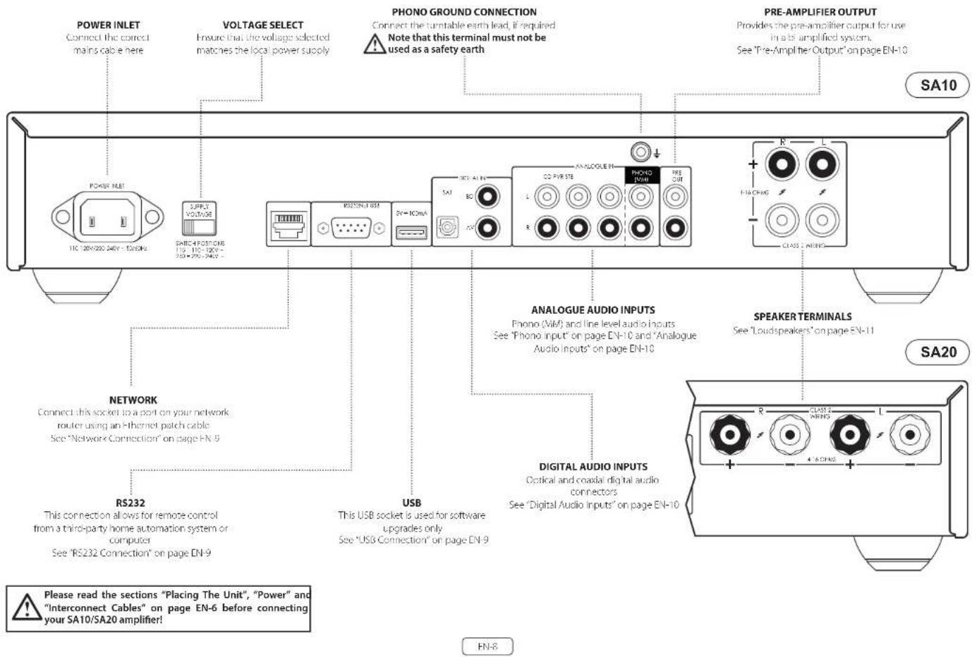
The amplifier is supplied with a moulded mains plug already fitted to the lead. Check that the plug supplied fits your supply - should you require a new mains feed, please contact your Atcam dealer.
In your mains supply voltage or mains plug is different, please contact your Arcan dealer immediately.
Push the IEC plug end of the power cable into the power socket on the back of the amplifier, making sure that it is pushed in firmly. Plug the other end of the cable into your main socket and switch the socket on.
Interconnect Cables
We recommend the use of high-quality screened cables that are designed for the particular application. Other cables will have different impedance characteristics that will degrade the performance of your system (for example, do not use cabling intended for video use to carry audio signals). All cables should be kept as short as is practically possible.
It is good practice when connecting your equipment to make sure that the main power-supply cabling is kept as far away as possible from your audio cables. Failure to do so may result in unwanted noise in the audio signals.

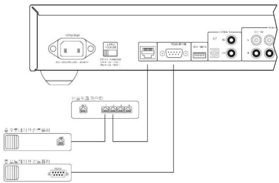
Rear Panel Connections and Controls

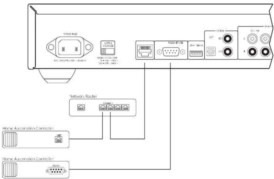
Network Connection
The SA10/SA20 can be connected to a local network, so that it can be controlled and monitored remotely. Please refer to the control document which can be found at www.arcam.co.uk for further information.
RS232 Connection
The RS232 input is for optional connection to a home automation system or personal computer. Various third-party systems are available providing sophisticated control over all your entertainment devices. Contact your dealer or installer for details. The technical details of the remote control protocol are available upon request, by contacting Arcam at support@arcam.co.uk.
USB Connection
The USB port is used for software updates only. For the latest software as well as further information, please visit www.arcam.co.uk.
FN-9
Operation
Switching On
The POWER button switches the unit on and off. The status indicator IHD indicates the state of the amplifier. It changes from red to orange then white if mains power is connected and the unit is switched on.
Setup Menu
The SA105A20 setup menu allows the customization of certain features of the amplifier. For details, please see "Setup Menu" on page H1-14.
Auto Standby
In order to comply with international regulations for consumer products, this unit is designed to enter a low power standby mode if no user interaction and no audio input signal are detected for an extended period of time. The unit can be brought out of standby by either turning the volume knob on the front panel in either direction or by pressing the key on the
remote control.
The available values are from OFF to 4 hours, in half hour steps.
Note: if the standby time-out is set to OH, the standby feature will be disabled.
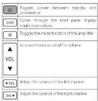
Display
Press the DISP button on the remote control to adjust the brightness level of the front panel display. The brightness level can be set to 'FULL', 'DWI' or 'OFF'.
If the SA10/SA20 is powered off with the display brightness set to 'OFF', the display will momentarily resume to full brightness then turn off when the unit is powered back on.
Phono Input
The SA10/SA20 provides a pre-amplification stage to treat the low-voltage output from an AM (moving magnet) cartridge. The PHONO input specifications are given in "SA10 Specifications" on page EN-16 and "SA20 Specifications" on page EN-17.
WARNING: NEVER play a standard line-level source into this input. This would result in serious damage to both your amplifier and speakers due to the extra gain that is applied and would not be covered under warranty.
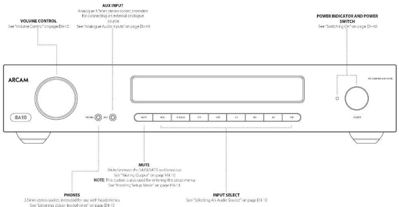
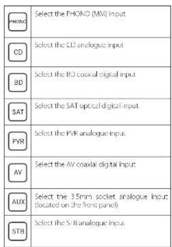
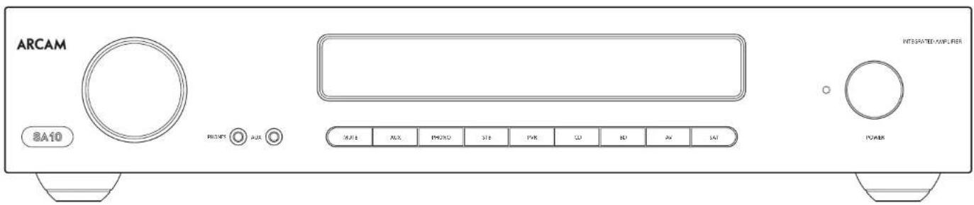
Selecting An Audio Source
Audio sources can be selected either from the front panel or remote control, by pressing the required button, labelled as AUX. PHONO. STB. PVR. CD. BD. AV. SAT
In each case, the source is selected from the input sockets with the corresponding name.
Note: The STB, PVR, CD, BD and AV buttons are also used for navigating through the SA10/SA20 set up menu, as described in "Navigating The Setup Menu" on page EN-14.
Digital Audio Inputs
The SA10/SA20 features two coaxial and one optical digital input, which can be connected to the respective digital audio output of your available source equipment. Although the inputs are labelled for specific devices, they can be used to connect any devices with a coaxial or optical digital output.
BD intended for the coaxial digital output of a Blu-ray or DVD-player
AVIntended for the coastal digital output of general audiovisual equipment, such as a VCR, TV or satellite receiver
SATIntended for the optical digital outputs from a satellite TV receiver or cable TV box
NOTE: The SA10/SA20 supports only two channel PCM audio input
Analogue Audio Inputs
Although the inputs are labelled for specific devices, all have the same characteristics and each may be used with any line-level product. The exception is the PHONO (MM) input. Please refer to "SA10 Specifications" on page EN 16 and "SA20 Specifications" on page EN 17.
AUX This is a 3.5mm analogue input on the front panel intended for use with devices such as MP3 players. To connect an MP3 player (or other portable audio device you will need a 3.5mm to 3.5mm cable connected (not supplied) between the AUX input and the headphone output socket of the portable audio player
STB Intended for the analogous outputs of a set top box
PVR Intended for the analogous outputs of a Personal Video Recorder, or similar device
CD Intended for the analogue outputs from a CD player
Pre-Amplifier Output
To use the SA10/SA20 as dedicated pre-amplifier, or as part of a bi-amplified system, connect the PRE OUT sockets to the input sockets of your amplifier. For connection details, see "Rear Panel Connections and Controls" on page FN 8 and for output specifications: see "SA10 Specifications" on page FN 16 and "SA20 Specifications" on page FN-17.
Adjusting The Balance
The balance setting allows you to increase the volume of one channel (left or right) relative to the other. Altering the balance may help restoring the stereo image for an off centre listening position.
To adjust the balance, press the BAL on BAL on
the remote control to change the left and right channel balance, respectively.
Listening
Volume Control
Use the volume control knob (or the buttons on the remote control) to change the volume. Turn the knob clockwise to increase the volume and counter-clockwise to reduce it.
Listening Using Headphones
The headphone socket (PHONES) accepts phones with an impedance rating between 16Ω and 2kΩ, fitted with a 3.5mm stereo jack.
The pre-amp outputs and speakers are muted when the headphones are plugged in and the front panel displays shows 'Headphone'.
The microphone output is always active, unless the amplifier has been muted.
Muting Output
The output of the SA10/SA20 can be silenced by pressing the MUTE button on either the front panel or the remote control. If the unit is muted, front panel power indicator will change to orange and the display will show "Mute", instead of the volume level.
To cancel the mute, press MUTE for a second time or adjust the volume (either by turning the volume control knob or by pressing the volume control keys on the remote control).
Processor Mode
Processor mode can be assigned to any input. In this mode, the SA10/SA20 is set to a fixed level. Please refer to "Processor Mode (PM) Input" on page HN-14 for details on how to specify which input is to be used in processor mode. For setting the desired fixed volume level, please refer to "Processor Mode (PM) Volume" on page HN-14.
Loudspeakers

Connecting Loudspeakers
There are many different ways of connecting loudspeakers to your SA10/SAP0 amplifier. The following section describes how to connect the speakers and amplifier for the most common configurations.
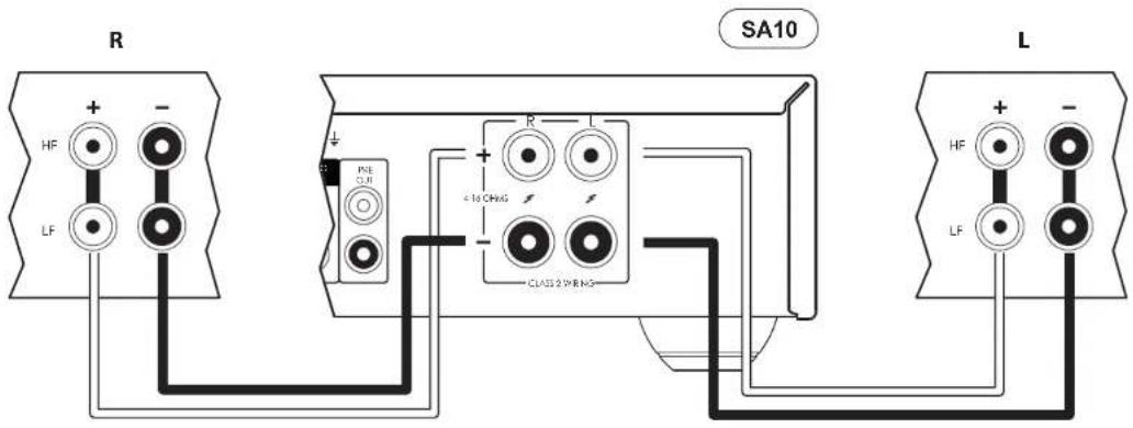
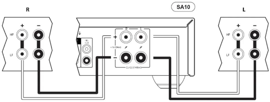
Single Wiring
If each speaker has more than one pair of connecting terminals, use the terminals labeled LF or Low Frequency on your speakers.
Connect the red positive terminal of the right speaker connection on the amplifier (labelled R + r to the positive terminal of your right speaker. Similarly, connect the black negative terminal of the right speaker connection on the amplifier (labelled R - r to the negative terminal of your speaker. Repeat the process for the left speaker, using the terminals labelled L+ and L- on the amplifier.
WARNING: If your speakers support bi-wiring, there will be a strip of conductive metal connecting the low-frequency (LF) terminals to the high-frequency (HF) terminals; this MUST NOT BE REMOVED in a single-wired system.
Notes On Making Speaker Connections
Do not make any connections to any amplifier while it is switched on. We recommend that your amplifier is completely disconnected from the mains supply before starting.
Before switching your amplifier on for the first time after connecting to speakers, please check all connections thoroughly. Ensure that bare wires or cables are not touching each other or the amplifier's chassis (which could cause short circuits), and that you have connected positive (+) to positive and negative (-) to negative. Be sure to check the wiring for both the amplifier and the speaker.
After making connections switch the amplifier on, select a source signal, then gradually increase the volume to the required listening level.
If you are unsure as to how your system should be connected, please contact your Arcam dealer who will be happy to help you.
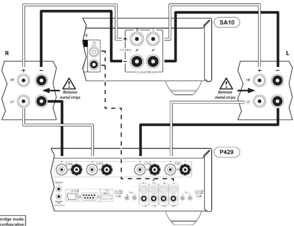
Bi-Amping
Sl-ramming is the separation of the amplification of low and high frequency signals over two amplifiers.
Bi-amplification requires the use of two amplifiers per channel. Normally, your SA10/SA20 is used to drive the high frequency (trecile) speakers, while a second amplifier (such as the Arcam P-429) is used for the lower (base) frequencies:
Connect the SA10/SA20 to the speakers as described for single wiring, with the exception that the SA10/SA20 should be connected to the speaker terminals labelled HF or High Frequency. Next, connect the F429 power amplifier to the LF or Low Frequency terminals, as shown in the diagram. A pair of audio Interconnect cables are also required to connect the pre-ampl output of the SA10/SA20 to the power amplifier inputs of the second amplifier.
WARNING: The strip of metal on the speakers connecting the low frequency (LF) terminals to the high frequency (HF) terminals MUST BE REMOVED. Failure to do so will result in damage to both amplifiers, which will not normally be covered under warranty.

In this example, the P429 is configured in bridge mode. Refer to the P429 user manual for various configuration modes.
FN-12
Remote Control
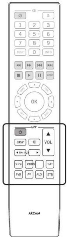
The remote control is pre-programmed for use with the SA10/SA20 amplifier and also an Arcam CD player. The information in this section applies to the AMP section of the remote control only.
Make sure the two AAA batteries (supplied) are installed before attempting to use the remote control.
-
With the remote face down, press down on the non-slip indentations of the battery compartment cover and slide the cover off.
-
Insert the two AAA batteries (supplied). Take care to insert the batteries in the right direction by following the ^+ and ^- marks in the battery compartment
- Slide the battery compartment cover back and lock it in place with a clock
The remote control requires a clear line of sight to the front panel of the SA10/SA20 to ensure reliable operation.
NOTE: The supplied remote control is designed to support both the SA10/SA20 integrated amplifier as well as an Arcam CD player. The section below applies to the AMP section of the remote control only. Refer to the CD user manual for description on the CD section of the remote control unit.
EN-13
Setup Menu
Before You Begin...
The setup menu allows you to configure various aspects of the SA10/SA20 integrated amplifier.
Entering Setup Mode
To enter the setup menu, press and hold the MUTE key on the front panel for approximately 3 seconds.
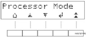
Navigating The Setup Menu
The setup menu can be navigated by pressing the front panel keys that correspond to the function shown on the display, as shown below.
To change a setting, simply turn the control knob left or right.
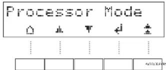
| HOME Exit the menu and return to the home display |
| UP Navigate to the previous menu option |
| DOWN Navigate to the next menu option |
| LEFT Navigate left or move to the previous field |
| RIGHT Navigate right or move to the next field |
| OK Save the current setting and move to next option |
| BACK Save the current setting and exit menu option |
System Settings
Display
Allows the brightness of the front panel display to be changed. The available settings are Full, Dim and Off. The default setting is Dim.
Balance
turn the SA10/SA20 volume control knob left and right to change the left and right channel balances, respectively. The default setting is 0.
Phones Override
Control whether or not the speaker outputs are muted when a pair of headphones are connected to the PHONES socket on the front panel. The default is Off.
Timeout
This option allows you to choose the length of idle time before the unit goes into standby. The available options are Off, 30 minutes, 1, 2 and 4 hours. The default setting is 30 minutes.
Processor Mode (PM) Input
Specify which input is to be used in processor mode. This mode can be assigned to any input. In this case, the SA10/SA70 output level is set to a fixed level. The default setting is None.
Processor Mode (PM) Volume
Specify the required volume level for the processor mode input. The default is volume is 30.
Filter
Specify which digital filter is used in the DAC.
C4 SDDP
Enables Contro 4 discovery.
PLL Width
Normal is the default setting and is appropriate for almost all sources. Select WIDE only if noises or signal interruptions occur (most likely from high jitter sources such as cable TV set-top boxes).
IR System Code
Change the IR system code that the SA10/SA20 responds to (either 16 or 19). The default code is 16.
Note: The supplied remote control supports IR system code 16 only and cannot be changed.
Version
Displays the software version of the unit.
System Update
This option allows you to perform a software update of the system.
System Reset
Restores the SA10/SA20 to its factory default settings.
Network Settings
Net Standby
Enables or disables the network control of the SA10/SA20 while the unit is in standby. The default setting is Off.
Note: The unit can still be controlled via RS282 commands, even when network standby is disabled.
RS232 Standby
Enables or disables the RS232 control of the SA10/SA20 while the unit is in standby. The default setting is Off.
Network Setup
You can set your SA10/SA70 to obtain an IP address automatically when it connects to your network. To do so, select DHCP On and press OK.
Some providers require that you enter a fixed IP address. To do this, select DHCP Off and press OK. Use the left and right navigation keys to move between fields and turn the SA10/SA20 volume control knob to set the values. Press OK (to save this settings).
The default network setup mode is DHCP On.
Network Info
Displays all the information related to the network setup, as follows: DHCP setting, IP address, MAC address and Network Name of the unit.
| Problem Check the following | |
| No sound | ☐ The SA10/SA20 amplifier is correctly plugged in and switched on☐ Your audio source is correctly connected, the correct input is selected and it is not muted☐ The SA10/SA20 is not in protection mode, as described below |
| Sound cuts out unexpectedly The SA | ☐/SA20 may enter a protection mode, depending on the fault being detected. The front panel LED will indicate the fault type, according to the list below☐ FLASHING BLUE: the internal temperature of the unit reached an unsafe level. Allow the SA10/SA20 to cool off☐ FLASHING RED: The SA10/SA20 amplifier disconnected a speaker short circuit. Should this happen, please inspect all the speaker cables so make sure none of them are shorted together. This fault is very common when bare wires are being used to make speaker connections☐ FLASHING ORANGE: The amplifier detected a DC offset. Following any of the faults described above, the amplifier will turn itself off and power to the speakers will be removed. To continue using the SA10/SA20, the fault must be removed and the unit must be turned OFF then back ON |
| The unit responds erratically or not at all to the remote control | ☐ There are fresh batteries in the remote control☐ The front panel window is visible and you are pointing the remote control towards it |
| The front panel display is blank | ☐ The display hasn't been turned off. Press the DISP button on the remote control, See "Display" on page EN 10 |
| Hum on the analogue input | ☐ All cables are making a good connection. If necessary withdraw the cable from the connector and plug it fully in again (turn the power off before doing this)☐ The connections inside the source cable connector are not broken or badly soldered☐ If the hum originates only when one particular source component is connected, that an aerial cable, or dish connection to this source is ground isolated. Contact your installation contractor |
| Can not connect to a wired network | ☐ The Ethernet cable you are using is correctly connected between the SA10/SA20 and the network hardware☐ The network is set up for fixed IP addressing and you have the SA10/SA20 set to use DHCP on☐ The network is set up for DHCP and you have the SA10/SA20 set to use fixed IP addressing. See "Network Connection" on page EN-9 and "Network Settings" on page EN 14 |
EN-15
SA10 Specifications
Continuous power output (0.5% THD), per channel
| Both channels, 80, 20Hz - 20kHz 50W | ||
| Both channels, 4Ω, at 1kHz 85W | ||
| Harmonic distortion, 80% power, 80 at 1kHz 0.03% | ||
| Analogue Inputs | ||
| Phono (MM) cartridges | ||
| Input sensitivity at 1kHz 5mV | ||
| Input impedance 47kΩ + 100pF | ||
| Frequency response (ref. RIAA curve) 20Hz - 20kHz ± 1dB | ||
| Signal/Noise ratio (A-wtd) 50W, ref. 5mV input 80dB | ||
| Overload margin, net 5mV at 1kHz 21 dB | ||
| Line inputs: | ||
| Nominal sensitivity IV | ||
| Input impedance 10kΩ | ||
| Maximum input 6Vrms | ||
| Frequency response 20Hz - 20kHz + 0.2dB | ||
| Signal/Noise ratio (A-wtd) 50W, net 1V input 100pF | ||
| Digital Inputs | ||
| DAC-PSS9016KOM | ||
| Frequency response 20Hz - 20kHz ± 0.05dB | ||
| Total harmonics distortion + Noise | 0.0007% | |
| Signal/Noise ratio (A-wtd) | 115dB | |
| Supported sample rates | Optical 32kHz, 44 | 1kHz, 48kHz, 88.2kHz, 96kHz |
| Coaxial 32kHz, 44 | 1kHz, 48kHz, 88.2kHz, 96kHz, 176kHz, 192kHz | |
| Bit depth | 16-bit - 24-bit | |
| Pre-amplifier output | |
| Nominal output level | 630mV |
| Output impedance | 730Ω |
| Headphone output | |
| Maximum output level into 600Ω | 5Wrms |
| Output impedance | 1Ω |
| Load range | 16Ω - 2kΩ |
| General | |
| Mains voltage | 110-120V or 220-240V, 50-60Hz |
| Maximum power consumption | 350W |
| Dimensions W x H x D (including foci), control knob and speaker terminals) | 433x87x310mm |
| Weight (not) | 84kg |
| Weight (gross) | 10.7kg |
| Supplied accessories | Mains leads Remote control 2 x AAA batteries |
| Continuous power output (0.5% THD), per channel | ||
| Both channels, 80, 20Hz - 20kHz 90W | ||
| Both channels, <Ω, at 1kHz 150W | ||
| Harmonic distortion, 80% power, 80 at 1kHz 0.002% | ||
| Analogue Inputs | ||
| Phono (WM) cartridge | ||
| Input sensitivity at 1kHz 5mV | ||
| Input impedance 47kΩ ± 100pF | ||
| Frequency response (ref. RIAA curve) 20Hz - 20kHz ± 1dB | ||
| Signal/Noise ratio (A-wtd) 50W, ref. 5mV input 80dB | ||
| Overload margin, ref. 5mV at 1kHz 21dB | ||
| Line Inputs: | ||
| Nominal sensitivity IV | ||
| Input impedance 10kΩ | ||
| Maximum input 6Vrms | ||
| Frequency response 20Hz - 20kHz - 0.2dB | ||
| Signal/Noise ratio (A-wtd) 50W, ref. 1V input 10dB | ||
| Digital Inputs | ||
| IDAC +SS303B/K2M | ||
| Frequency response 20Hz - 20kHz ± 0.05dB | ||
| Total harmonics distortion + Noise | 0.0007% | |
| Signal/Noise ratio (A-wtd) | 115dB | |
| Supported sample rates | Optical 32kHz 44.4 | kHz, 48kHz, 88.2kHz, 96kHz |
| Coaxial | 32kHz, 44.1kHz, 48kHz, 86.2kHz, 96kHz, 176.4kHz, 192kHz | |
| Bit depth | 16-bit - 74-bit | |
| Pre-amplifier output | |
| Nominal output level | 630mV |
| Output impedance | 280Ω |
| Headphone output | |
| Maximum output level into 600Ω | 5Vrms |
| Output impedance | 1Ω |
| Load range | 16Ω - 2kΩ |
| General | |
| Mains voltage | 110-120V or 220-240V, 50-60Hz |
| Maximum power consumption | 500W |
| Dimensions W x H x D (including foci), control knob and speaker terminals | 433x87x323mm |
| Weight (ncl) | 9.2kg |
| Weight (gross) | 11.1kg |
| Supplied accessories | Mains leads Remote control 2 x AAA batteries |
All specification values are typical unless otherwise stated. Arcam has a policy of continuous improvement for its products. This means that designs and specifications are subject to change without notice. E&OE.
Worldwide Guarantee
This entitles you to have the unit repaired free of charge, during the first five years after purchase, provided that it was originally purchased from an authorities Arcam dealer. The Arcam dealer is responsible for all after sales service. The manufacturer can take no responsibility for defects arising from accident, misuse, abuse, wear and tear, neglect or through unauthorised adjustment and/or repair, neither can they accept responsibility for damage or loss occurring during transit or from the person claiming under use quarantine.
The warranty covers:
Parts (including disc drives) and labour costs for two years (from the purchase date (see below for additional terms and conditions). After five years you must pay for both parts and labour costs.
Disc drives (of any type) are covered under this warranty for two years from the purchase date.
The warranty does not cover battery replacement at any time.
The warranty does not cover transportation costs at any time.
Claims under guarantee
This equipment should be packed in the original packing and returned to the dealer from whom it was purchased. It should be sent carriage prepaid by a resuable carrier - not by post. No responsibility can be accepted for the unit whilst in transit to the dealer or distributor and customers are therefore advised to insure the unit against loss or damage whilst in transit.
For further details contact: Arcarm at arcam/support@harman.com
Problems?
If your Arcam dealer is unable to answer any query regarding this or any other Arcam product please contact Arcam Customer Support at the above address and we will do our best to help you.
On-line registration
You can register your product online at www.arcam.co.uk.
MANUEL

ARCAM HDA
AMPLIFICATEUR INTEGRE
SA10/SA20
Bienvenue
Amplification double
Telecommande
Menu de configuration
Amplification double
SA10 Specifications NL-14
SA20 Specifications NL-15
Activecn. Control 4 discovery.
PLL Width-PLL-breedte
Al工程技术 has the most numerous of experience in design and production. It is one of the best-known firms in Italy, which focuses on creative design and technology. The company's main focus is on designing and developing innovative products that can be used to create new opportunities for the market.
IpeepHaayanompa6oTbCMeHIO... RU-12
CnCTeMHbIe HaCTpOIKU RU-12
Cetebie hactpoKn RU-12
YctpaHHeHHeHcnpaBHOCTe RU-13
Texnueckx xapaKepncnSA10 RU-14
TexHueckx xapaKtepncTNk SA20 RU-15
TapaHTnNo BcEmy Mnpy RU-16
0630p
Ycnnntenb Arcam SA10/SA20
M imperans-bir yinmert Ancam SATO/SA20
eceeeee nteosokkchoe kaechtBO bkyo,
103040BB RBAHACKCHIOE OHHHBRYBHNACM
My35kR.
S OCHORA STERO YCYNTHIO DEKAM MHOCHANDHOMO KOMOHAIARCAM BOCINPACPOBOYAKY CYPHYCHOE 30Y CYPHYCHOE PPOHOHO CHPCPOHO HONPOHO HONPOHO HONPOHO HONPOHO HONPOHO HONPOHO HONPOHO HONPOHO HONPOHO HONPOHO HONPOHO HONPOHO HONPOHO HONPOHO HONPOHO HONPOHO HONPOHO HONPOHO HONPOHO HONPOHO HONPOHO HONPOHO HONPOHO HONPOHO HONPOHO HNONPOHO HNONPOHO HNONPOHO HNONPOHO HNONPOHO HNONPOHO HNONPOHO HNONPOHO HNONPOHO HNONPOHO HNONPOHO HNONPOHO HNONPOHO HNONPOHO HNONPOHO HNONPOHO HNONPOHO HNONPOHO HNONPOHO HNONPOHO HNONPOHO HNONPOHO HNONPOHO HNONPOHO HNONPOHO H NONPOHO HNONPOHO HNONPOHO HNONPOHO HNONPOHO HNONPOHO HNONPOHO HNONPOHO HNONPOHO HNONPOHO HNONPOHO HNONPOHO HNONPOHO HNONPOHO HNONPOHO HNONPOHO HNONPOHO HNONPOHO HNONPOHO HNONPOHO HNONPOHO HNONPOHO HNONPOHO HNONPOHO HNONPOHO HNDPOHO HNDPOHO HNDPOHO HNDPOHO HNDPOHO HNDPOHO HNDPOHO HNDPOHO HNDPOHO HNDPOHO HNDPOHO HNDPOHO HNDPOHO HNDPOHO HNDPOHO HNDPOHO HNDPOHO HNDPOHO HNDPOHO HNDPOHO HNDPOHO HNDPOHO HNDPOHO HNDPOHO HNDPOHO H ND PO HO NDO HO NDO HO NDO HO NDO HO NDO HO NDO HO NDO HO NDO HO NDO HO NDO HO NDO HO NDO HO NDO HO NDO HO NDO HO NDO HO NDO HO NDO HO NDO HO NDO HO NDO HO NDO HO NDO HO NDO HO NDO HO NDO HO NDO HO NDO HO NDO HO NDO HO NDO HO NDO HO NDO HO NDO
Bianapao yinwenpo SA10/SA20 8aasa nohman Myikaio HAOHOTUANYI ANP
yctahOBka yctpOCTBa
YcHIOOHC YCCHINH HApooH TbeDPOBIOHOIOHOIOHOIOHOIOHOIOHOIOHOIOHOIOHOIOHOIOHOIOHOIOHOIOHOIOHOIOHOIOHOIOHOIOHOIOHOIOHOIOHOIOHOIOHOIOHOIOHOIOHOIOHOIOHOIOHOIOHOIOHOIOHOIOHOIOHOIOHOIOHOIOHOIOHOIOHOIOHOIOHOIOHOIOHOIOHOIOHOIOHOIOHOIOHOIOHOIO HOIOHOIOHOIOHOIOHOIOHOIOHOIOHOIOHOIOHOIOHOIOHOIOHOIOHOIOHOIOHOIOHOIOHOIOHOIOHOIOHOIOHOIOHOIOHOIOHOIOHOIOHOIOHOIOHOIOHOIOHOIOHOIOHOIOHOIOHOIOHOIOHOIOHO
11 He yubunbanbue SAIO/SAO ha yubunbanbue MOHONBOJUJIYIIEPCHEPOBAMCIFU.
Li He yizhanbaibinrue yizhongtirb. Bokoup IpoipaoiHua Huaqzhi KauKuoHui unkyu hui Maikouri CIOBIE, CINI TANHE COEZHEN HAOPOHN BENTUHAI, KOKHTZUYU YINJITAN SAI/SA20
RyDcYAMC303ET ERO HOBOAEI OO epee DOKYTAJNIO 10 HOMATOH DOKYE
He pachonaraihna huiyipn aoyx npo hnoe HpipeyDcpepy 1y ycnHnne, TAK KKT OMOKETATyHNHtE BHTNIOHOO xOaIbAoeO POaIbTOPO. IUPINPAPR K CCHCCHNOHARHPaCpHIOYCKYNHNN, (XocPcSO, yctalcoNHeHIOI Hg YCNHNN, TaOeHarpTeC).
YQEDTEC,HTIO PENEMI KFTHOABDCHTALHOH YIPOBPHN CIPINA OJ HAI NCHA HJPCDHCHEKAM HNCHEKAPRI -HPOPHMCHN CHYN,MO BCGY MCLATG POZ807 PYNILDA KCTAHONHOY YOIAGSHIN
He yctanaanbapre bckporpnpbpa HcypocnKcipkpcnnpaaonpncn CNYCTBETeH K pOw300dHM PCHYKKM NcckpOaHNNH HOMCWM, BaeHHBQIPW DOnOHH INyH, HOHNO HE pactoHnH 1AckpONComPbAtCB CHILKOM GHNHO
LI YUQI XING MOHAI CHIN HONGCHINA HONGCHINA CHINHK HONGKONG HONGKONG HONGKONG HONGKONG HONGKONG HONGKONG HONGKONG HONGKONG HONGKONG HONGKONG HONGKONG HONGKONG HONGKONG HONGKONG HONGKONG HONGKONG HONGKONG HONGKONG HONGKONG HONGKONG HONGKONG HONGKONG HONGKONG HONGKONG HONGKONG HONGKong HONGKONG HONGKONG HONGKONG HONGKONG HONGKONG HONGKONG HONGKONG HONGKONG HONGKONG HONGKONG HONGKONG HONGKONG HONGKONG HONGKONG HONGKONG HONGKONG HONGKONG HONGKONG HONGKONG HONGKONG HONGKONG HONGKONG HONGKONG HONGKONG HONGKON HONGKON HONGKON HONGKON HONGKON HONGKON HONGKON HONGKON HONGKON HONGKON HONGKON HONGKON HONGKON HONGKON HONGKON HONGKON HONGKON HONGKON HONGKON HONGKON HONGKON HONGKON HONGKON HONGKON HONGKON HONGKONDANG
TneKtponTuHne
ДИЕНСТРКРКСТСТСТСТСТСТСТСТСТСТСТСТСТСТСТСТСТСТСТСТСТСТСТСТСТСТСТСТСТСТСТСТСТСТСТСТСТСТСТСТСТСТСТСТСТСТСТСТСТСТСTSCSCHNHNHNOYUHNHNHNHNHNHNHNHNHNHNHNHNHNHNHNHNHNHNHNHNHNHNHNHNHNHNHNHNHNHNHNHNHNHNHNHNHNHNHNHNHNHNHNHNHNHNHNHNHNHNHNHNHNHNHNHNHNHNHNHNHNHNHNHNHNHNHNHNHNHNHNHNHNHNHNHNHNHNHNHNHNHNHNHNHNHNHNHNHNHNHNHNHNHNKNNNNNNNNNNNNNNNNNNNNNNNNNNNNNNNNNNNNNNNNNNNNNNNNNNNNNNNNNNNNNNNNNNNNNNNNNNNNNNNNNNNNNNNNNNNNNNNNNNNNNNNNNNNNNNNNNNNNNNNNNNNNNNNNNNNNNNNNNNN
FIOB 100 MPKIOOJI KIOIOI KIOIOI KIOIOI KIOIOI KIOIOI KIOIOI KIOIOI KIOIOI KIOIOI KIOIOI KIOIOI KIOIOI KIOIOI KIOIOI KIOIOI KIOIOI KIOIOI KIOIOI KIOIOI KIOIOI KIOIOI KIOIOI KIOIOI KIOIOI KIOIOI KIOIO!
BxOJ 3ByKoCHMaTeTnA
YcHnT 50/SA20 BnONHHRE
BD PpHnHnn Hnnn nnnn nn nnnn nnnn nnnn nnnn nnnn nnnn nnnn nnnn nnnn nnnn nnnn nnnn nnnn nnnn nnnn nnnn nnnn nnnn nnnn nnnn nnnn nnnn nnnn nnnn nnnn nnnn nnnn nnnn nnnn nnnn nnnn nnnn nnnn nnnn nn
AVIpHnHCHNCHHHKINKINKINKINKINKINKINKINKINKINKINKINKINKINKINKINKINKINKINKINKINKINKINKINKINKINKINKINKINKINKINKINKINKINKINKINKINKINKINKIN
SATPCHHINHCHI 100 FADMMNHOO CYTHINKOGOTKIKKENBHTGNTESNEA
IPNMEYAHWE. Yucunmteb SA10/SA20 nooepdkaewae molo kbo deyakhaanuho hoo oyoauhncn PCM
AhaorobbyeaymOBXoBbl
XOT 374 axoD nppeBnHnnn nnoeepenBbXyOCTOBH, OHN NMOE OONHOHxNEXA XAPAKTEKNTKNK KANKHN 374 axoBNO HcNOHNO BcNOBtBnTg DnnoPNOCHNEI NOBOERYPOCTBaCnHOHbXOeDOPoDIOJNOxoIroI paoRIOPOCTBaHbXOJI, ZKsOeKHOHbCnB PHONO (MM) UpOBoHcNcM a Panyhoxn cTxnxNaeKne I XAPAKTEKNTKN SA20 Na CTs. RU-15. TExnAnekne XAPAKTEKNTKN SA20Na CTs.RU-15).
AUX AALIOIOH HKOJ 55 MM HOOPDHE
TCHH TPOOHOHOHOH JPN
KIOIOHOHOHOH CIOIOHOHOYOPOTOHMO
KAK MFO-NEeepa DNO MOIOHOHOH MP3-NEeepa HApyeroo NopotOHBOHO
IPOIOHOHOHOH HIOOOOHPoH KEOO
3.5 MM/2.5 MM (Ho KAOO H KOIOIO) KO
kooy AUX HA cyTOPOCTe HnEezy dno
IuyuiohoN Oeepa
STB Prrnneepnnn nnnnneennnnn T
PVR PEPD3AHANH HIN DPOPHIOHEH REPOCHABHBX SHAOBHOHTFOOHN 100000000000000000000000000000
CDI pppHHHNN HIN TIOKHOH 1000000000000000000000000000000000000000000000000000000000
BbIXoI npeducnnnten
JIN CENKO BAOHAI SA10/SA20 B KANHELE ZEOTI HONG TUPCYNCHUOLIMI MUN YUCHEN CHUMCHU C JHOPKHNYUKENIEV NKPOKHOWE PABZHM PRE OUT K DIOBHM PAZBEMYCAIATPEN C POMOJIYABAEBN NPOPOBIEe o NKPOKHOWEM CM. B PADIEN XANDEHNI TYAPONELIN H PABZHM NAOHAYI HAMCOHNAH CT CR, RU-6. INHPOPALNIAO AOKPPEKHAETXIK ANOYIKYIN CYTHIANA CM, R PADIENeTAXINCKNEKAKPRAKHTENSA 50-13 CT CR, RU-14. T AXINCKNEKAKPRAKHTENSA 50-13 CT CR, RU-15.
Perynupobka 6anaHca
HucipokKa BanaKc KusuBn yssnnnBnbpomkOcbgno khsanb (neBPORn npaboro) no OTHouMe KdyCmY Kany. DTo NOMoWETBOCTOBHTBkyDykoBcyEe, ECAI TcNOAeHcyCuyNtAaCuaCnHcO C HocTnHooCIOH pa.
DIn a cypyrnpboh BanaKc moy JbcBm npabv
图1-8
HANAMNACNTNATEYPIKONBAI 113
PpocnymbHne
Perynnpobkarpomkoctu
Iy ypaHnn HpyoHn rpoKOn HnOy3yPe pykny peryaHOBpRPOKCHN KIN KOHnHaYnE PycTaunHNOO y paBnCn. TcoB npBnBnT PPOKCHN HnepRePpyoHn aacOBn Cnpe, TcoBmybHnBnT nPoTbNACoBn
PpocnyuBaHnueepe3HayuHmK
Thee 1n HAYIINHOO (PHONES) NOEPOHNOAER HAYIINHOO C COPTOPREHHPW 06 CM p2 KCM co CICPCOOOCHCOO PAHOM/3.5 MM
11111111111111111111111111111111111111111111111111111
BKNQD 12HJHJHJNKBKINKIOHNKOBENOHKOB,53VOCHTOHNBPHCNYAHS,KOTKEYOKYIKONTHOTCHOUH
OTKIOUOHeHNE BbIXoHOrO CnRHaHa
BauKbOOMHcM 5ATGADJXMOHcKOBIOHcK HAKK KOKY MUTE n neoednien raenrnnn nnrnnrnnn nndtactaunncnHOY npaaeHHN. Eca aayyctooTBA tONKHN, INmHnnp TnAHTAHN HnCpOeN NnOHn TOpHnOeHHN, a HnIeueaeNnEcoOyOHn PPOKCKOTOnobapcketocooeBuHne34yoktonIOeHh. HbOblkKnHTbBk, NKMMTe KNHOrM KUTE cae paa IyHKNNs cYORHb (XMOKOCIN CIOOMN)pyKuKcPcYBIPOBOM XMOKOCIN MNEKCHKcPcYBIPOBOM PPOKCKOTnBaTtSeDnAIOHIOYpAAHNT
Ppoecccopnbpckm
PpOecoepnep Pekm MIOHO HauHHTb NcOoby XOyD. B 20M peNIMe baoDIOOH CTHAR. SAO/SAO8
KHCCHcyTt HIOI yOPOe. TpOpoBee o TOM,
KAB 49Bp8XoD, KOTOPOVIE HeoOxOIMO IaHsIHTb
PpOeocOeppn pokm, CM, B "FV rpt. BDOHHe
PpOocOeppno OPOkMe DIOHXoD HA CIO, RU 12, EPM
HApOIO FIKpOoiHOI HOOpyr pOoKoMc CM,
Saepen FVVolume -PpOkoCb B npOoeopcoH
pckmNcHcA pICR.PU.12
Akyctnueckne cnCTembl
IopKnIOUeHHe aKcTnueckoCNCTEmbl
CyIeTeByET HeKoJIbKO pAaHINbK cNoOc0B
NpOIOIOIOIOI bckyTHcNIOcK cKcYnTtHO
SA10/SA20. B CngyIOUepe Paqene npOBeHIO
OIOIOIOIOIOI HApOIOE PAcipOpCnIOHbX
KIOIOIOIOIOI pNOIOIOIOI KOnIOIOHcYNCIOTEn.
OdHonpoBODHoe noDKnUoyHeHne
HUYI KAKIOXKONOHOKOHOHOPAIAKOMM, HIOCTOYE KEMN C MAPPKAPCKL LF (H) 100 HIXKMECACTOTB.
KIOJIOHIOI KPACHNIO HONKOHNIOHNI PAHOHNOYIOHIN CAMBOHIO R+KONOHNIOHIOH KOIMNE KONOHA. TAKMI KOpCABIO PNOKONMOIe CHNPOUAPENHHN PAHBN YCNIOHNTER CCMBOHIO R- K OIPMIAHIOHIOH KUMWc HOBHOKONOHII. NTOOPHTRE pnoecn dnn neoB KOHOH4, pyKOHOCTOYNB COOTDBTBCYUMNH MAKKPNOOAKMM L+H-LAHCYNHNN
BHMMAHHEI Echu cnlohbyeMe KOanHou nObeepxukamn OeyxnpoBHOe noKIOHouHenue, H3KooHAcommHne KNEEMM (LF) 6yDYM coEDUHenb C bKcOKOHAcommmHmu KNEEMAMH (HF) cNoOMuBo nepeMHcu u npOboDHeMa eMa - HE CHMMATE mny peMbnky npu oDHonpoBOMn noKIOHouHenu.

DOnonHntelbHa HΦopMaun O NOkHoueHN KONOHOK
I He HnHnHnHnHnHnHnHnHnHnHnHnHnHnHnHnHnHnHnHnHnHnHnHnHnHnHnHnHnHnHnHnHnHnHnHnHnHnHnHnHnHnHnHnHnHnHnHnHnHnHn H n H n H n H n H n H n H n H n H n H n H n H n H n H n H n H n H n H n H n H n H n H n H n H n H n H n H n H n H n H n H n H n H n H n H n H n H n H n H n H n H n H n H n H n H n H n H n H n H n H n H
BIOHMMIHOPOPESCEC OEOAIEHNEPEE BPOBIOHNNY CYNNTHNE NOOE NOKIOHNK HKNHY KONOHK, YOENAEb, ITO OROHNHE PPOOBAI KAN KABELI HE KACAOBDA PRy DQy RNY HIN KOPRYS CYNNTHNE (20 MOER PPOPNCTK K OKOTKOY MAMBAHNIK INOPOHNI E CO SODNOHNEM NIONOCTA. He 3a5dyepe POPOPIETK OPOKIOHNI KKK CYCNTHN, TAK KOHNHOJ.
1HIOOHOHOHOHOHOHOHOHOHOHOHOHOHOHOHOHOHOHOHOHOHOHOHOHOHOHOHOHOHOHOHOHOHOHOHOHOHOHOHOHOHOHOHOHOHOHOHOHOHOHOHOHOHOHOHOHOHOHOHOHOHOHOHOHOHOHOHOHOHOHOHOHOHOHOHOHOHOHOHOHOHOHOHOHOHOHOHOHOHOHOHOHOHOHOHOHOHOHOHOHO HO HO HO HO HO HO HO HO HO HO HO HO HO HO HO HO HO HO HO HO HO HO HO HO HO HO HO HO HO HO HO HO HO HO HO HO HO HO HO HO HO HO HO HO HO HO HO HO HO HO HO HO HO HO HO HO HO HO HO HO HO HO HO HO HO HO HO HO HO HO HO HO HO HO HO HO HO HO HO HO HO HO HO HO HO HO HO HO HO HO HO HO HO HO HO HO HO HO HO HO
EeBn H2 h3e, kX pNtBIO NIOKIOHbIy AkyCTNEKIO CPTMcy, oOpTHTec 33 nOLOBIO K MECTHOY dyNCy Arcan.
BBOHoe ycnneHne
JIOIOIOOYIOIOIOIOIOIOIOIOIOIOIOIOIOIOIOIOIOIOIOIOIOIOIOIOIOIOIOIOIOIOIOIOIOIOIOIOIOIOIOIOIOIOIOIOIOIOIOIOIOIOIOIOIOIOIOIOIOIOIOIOIOIOIOIOIOIOIOIOIOIOIO
DIOIOHc yckcnne Hpeyj mCIOBcO30HJI DByk ycknntenE h KAMAN OOBHO SAIC/SA2O MIOHcyETON CIOYCNTH CNHHTA HsCOKHOCTOHEX H EHHMNO, A stopkyCNNTEN (IaHmNep, Arcam P423) 1-UIHpHNNMAKHKHXKXHKTQTO (6OO).
KoOIOHOH: SAT/SA20 K KOIOHOH, KIOHOHBO HIOPOHOH DIOHOHOBIO HOHOHOHO HOHOHOHO HOHOHOHO HOHOHOHO HOHOHOHO HOHOHOHO HOHOHOHO HOHOHOHO HOHOHOHO HOHOHOHO HOHOHOHO HOHOHOHO HOHOHOHO HOHOHOHO HOHOHOHO HOHOHOHO HOHOHOHO HOHOHOHO HOHOHOHO HOHOHOHO HOHOHOHO HOHOHOHO HOHOHOHO HOHOHOHO HOHOHOHO HOHOHO HOHOHO HOHOHO HOHOHO HOHOHO HOHOHO HOHOHO HOHOHO HOHOHO HOHOHO HOHOHO HOHOHO HOHOHO HOHOHO HOHOHO HOHOHO HOHOHO HOHOHO HOHOHO HOHOHO HOHOHO HOHOHO HOHOHO HOHOHO HOHOHO HOHOHO HOHOHO HOHOHO HOHOHO HOHOHHO HOOOHHO HOOOHHO HOOOHHO HOOOHHO HOOOHHO HOOOHHO HOOOHHO HOOOHHO HOOOHHO HOOOHHO HOOOHHO HOOOHHO HOOOHHO HOOOHHO HOOOHHO HOOOHHO HOOOHHO HOOOHHO HOOOHHO HOOOHHO HOOOH HOOOH HOOOH HOOOH HOOOH HOOOH HOOOH HOOOH HOOOH HOOOH HOOOH HOOOH HOOOH HOOOH HOOOH HOOOH HOOOH HOOOH HOOOH HOOOH HOOOH HOOOH HOOOH HOOOH HOOOH HOOOH HOOOH HOOOH HOOOH HOOOH HOOOH HOOOH HOOOH HOOOH
Peped hauanom pa60tbc MeHIO...
Me40 HACTPOINIOBOLRET HACTIOHN PAHANBHNNI OYKIMNIOIIOIPOAIHOO YOLOONCIB 5A10/SA20.
BxOaB MeHIO HAcTpoKn
DINK OXDA B MCHN HACPOHN NAKMITE Y DEDAMBNTY HOHNO MUTE H1CPCN 104064 104064 3 (3C)
NepexoMekdy nyHKTaMM MeHIO
JIBINCPCXQOXOXYHNYKTHMWCHOHIOEXOHN
NONCSYNEKTHKONIKNAIPEEPENAHNI
CCOOCTRNCNKTCHONKOKHKBNHADACHNCKTOKSEBHO
HAPCKCROKHNK
HIN MCHOH HAPAMCPOB HACPOPON PPOOIO NOREPHIpy Ky peyipcknKpOMKOHN BHERBIL
| ДOMОЛ | БИСОД МЕЦИЙ ВОЗВЕРК ПИЗНСИЙ NGАПАД,ПИЗПСИЙ NGАПАД | |
| HABEPX Γ | БЕХOD K ПЕДДУСЕМУ ПИKHТу MEHNO. | |
| BHN3 Ispc | СХOD K C J C D Y O U S C M Y P H-KTу MEHNO. | |
| BЛБОΓ | СЕМЕSHENDE HAIPEO KIM NIPEREXPOД КПЕДHIVUSSMу TИKHТу MEHNO. | |
| BIPABO | TESEMSESHENDE BIPASO KIM NIPEREXPOД КСЕДYUSSMу TИKHТу MEHNO. | |
| OK COxPd | СИСТС.HAICIPOCKI KIPCRIXOD КСЕДYUSSMу TИKHТу MEHNO. | |
| HA3AДС | СХАLE ПЕДLEЕ ДASTROКЕД SFXODNIS РСРКИД NACIPKRIAN AIOO TUYKDA MCHNO. |
CnCTeMHbIe HAcTpOpKn
System Settings
Display - Ducnnei
NoBnEHT HAcTPOHb PkOCTb DcFRe Ha Npeaehn HnHnHnIyHnHnHnHnHnHnHnHnHnHnHnHnHnHnHnHnHnHnHnHnHnHnHnHnHnHnHnHnHnHnHnHnHnHnHnHnHnHnHnHnHnHnHnHnHnHnHnHnHnHnH
Balance - BaanHC
Tobopanaatane py-kyr pyenipnrokpyrnpocctA SA10/SA20 AteBn BnPABO, T06B PAMHHTB 5uHcI cIOHO I pTOHO KANHO. HIO YCMNHBH YCJTHOBCHD JHNKNCIO.
Phones Ovr - PnpOpntet HayuHkoB
Beknohne IM OKIOKHeMe Inpovopetra HauHINKO, KORDA 38yK KOHOHOK OTKHOHcEpi NpIIOKHOHCHM YIKHOHKeK P3056X PHONES HAIOPTKII TAKHIN. IyoMOnAHNO BMOpaHO SHaHEHe IM BbKn.
Timeout-BpemnDnepexodaBpekmOxndaHn
PBOBIOHET BpObI pNOPOVOTIK BOEEMHKOJA YCIPOPCHO HIOHOHUYEIE,IO CIEMOE KIOPOO OYBCNHOHTOPOXIMI PPOMIMOKOMNBAJI (JQYTHN) 2HNHEKIN. BbKn, 30 MHTy1, 1 Hc, 2 H4 cHa. 3AHNHE NOYMNHAHIO 30 MNHTy1.
PM Input - Bkluoyene npoeccnporopekmma dna BXoda
Eeeppe 10xO, KOTbH NEO6DIMO HCNOB303B b PooecoppIO pKEMME. 3OT pEKMM KOHK HBNAMN 1kOxyO. IaM NIOHANSAHMAI OIO pKEMME 2auoOH CNKTHA SA10/SA20 fKcKpyETnHa OH aOpH yOboH 3a-1HcHNE NOYHOHN-HER
PM Volume - FrpomKoctb V npouecccopHom pekimme
YANKATE yOPOBEN PPOKOCCTV KOTOPYNEOXIOVMO HONTOB3037B TAOA a PPOUCCOPHOM POKIM. YOOCHN1PPOKOCHTY OYUMNHOH-30
Filter-OpnbTp
BbepmeufoocnfnbtpnnLAP
C4 SDDP-C4 SDDP
Aivbpyc06hApynnnto Contr 4.
PLLWidth-ⅢnpnA PLL
Normal - STO HACPTOPKIO NO yMOHTHNO, KOTOSAOI HOPOM I PAKINWECCK UNB BCCNCHCAKOKB BuCpOc WIDE TOHBO CCGUHNCBIH BHTBACCTYIMNHNrpoTADAHUE CHNIA (KOPEE DCERO, N3 VKTOHNIKKO C BNCKOMI YPOHEEM, DPOKANMA, TAKXK KABENHKE TEHNEKAPONKHI PNTACTAKR).
System Code -KoI cnCTembl
Himele-Heine Hk-Koja Csiemaru, Hk Kotojuro 10a/SAO/26 (16)Kn:Ko yomunahuo -16
Pnmeueyue. BxovuB u konmneK noocbuknynnb duimhanuunhooo ynpaenlne nooepdkaeumHK-koc cuiembe < 16% ,uomkohne moekerm bmuuenn
Version -Bepcua
OipaaeHepcno10ycipoeiBa
System Update - CnCTemHoe 06HOBNeHne
PiOaONEToHIOBnTbTOCVCNTEM.
System Reset -C6poc cnCTEmhbx Hactpoek
BOCTAENBAHNEACTPNOKAYCYPIONCTBA SA10/SA20 3do300DCKNIXBHEIN.
CetebbIe HAcTPOKn
Network Settings
Net Standby - Ynpablenne no cetn B peKIMe OxuaHIN
BIOHOBIE IN OTIOHOIE CEREBORA ynpaBnHIN YCUNTRENEA510/SA20O BEXNME ONDAHIN 3I8HHEI NOYDHYAHOHO-BiHK.
PnmeaHae. YrpoTcHbOMHOy yprBHTbC nOcmouho HtepeoRcS232, dae cnaYtpaaneHHe IIO CENI R PCMNQ OOyEHNKOBNO
RS232 Standby - RS232 B pexkme Oxndn
Bkoohne N oKIOKHOHe RS232 ynpaHHe H cyHmEeSAL0/SA20RnKHeMe OcHApHn 3HaueHHe ITOyMOHnHBO BbIK.
Network Setup-Hactpouka ctn
BNVONKETHACPOPTABOTOMATUMHECKOE NONGYIHEPILAPCCSAYCPOPTOBAMSA10/SA20 INPIIINIKKIMKCHCENJINHIOHOBDICNDCDHPKNCINHKAHMOK
3 33BACCHIOITOo00000000000000000000000000000000000000000000000000000000000000000000000000000000000000000000000000
Perehakhtpokn Kcn no yMcTAnHko yctanobTe 3 24614DHC PkN
Network Info-CeteBaHΦopMaun
OTo6bKaTe AIOHmPoAHO, OTOcHooYCK HactoepCte, a cneOyoeu nopnKpRapamTbpDHCpIPaPc, MAC aIpcN CetEBoe MM yctOoBtQ3.
| Iproktenyaчу hygienoviproblety | |
| Осуctrуету备受 | ☐Удзгель SAT0/SA20 Корретиою подддддддддддддддддддддддддддддддддддддддддддддддддддддддддддддддддддддддддддддддддддддддддддддддддддд徳 ☐Исторik astydokhanaya Корретиою поддддддддддддддддддддддддддддддддддддддддддддддддддддддддддддддддддддддддддддддддддддддддддд徳 ☐Ситерь SAT0/SA20 He xushoia o pekivnoi zai kovnokho niike. |
| Визлихосншимовспесук | 3.Danishinoxis ot obuchyckhonsoi ouchkiy KysuHINCH, SAT0/SA20 Moktii Kupoi B pekimba saatci Tyn BozhiKusoi ouchkiy oboushenbctcr c noovouksie CBetopodnogho nykustokapla h napejni nainai. Tndpochioe oncncane ouchok poyedek do nino hme. ☐MUTA-1 CHVIM-Khyipren-Haunepayr yucpovnka Hukoniknok O ypovnka, Hoc6xodmvo, nochbu yucpovcTBO SAT0/SA20 oxadnokoc. ☐MUTAET KXAPCHBIV: yuchniKOBAT SAT0/SA20 obuchycknok kopoKoKos Kauyaknok koHONKII, B IOM CAYUO OMOPIRE Kce Kaobn KauyHKII, YC6B N ybevymnck R DcyschymnKorpoKIO KORPOKIO BAKMANKHI, 3E IOpOBIgBa BAOKANIKI JOKOJIHO KACIO Ipy MIOYIOKHNKII KOUOHNKII OLOVOUKNKIO OLOVOUKNKII OLOVOUKNKII ☐MUTAET OPAHKEBVM: yuchniTelemem obuchycknok osmeelime noctofoi coxtablanoioue cyharhala. Ipy obuchycknok kaukoiHaboNko HBeR NIOBcHbHbK HBeR NIOBcHbHbK bukmikteca n ne pekpauet naduy natohnai Koro-KAM. YC6B NOpOJNKHb KoNtOBAOBAHNE SAT0/SA20, uycpahnte nplopenemy. BOKKIOHNTI Natev choba BOKKIOHNTI yucpovcTBO. |
| Yucpovstao otrogoe c pepeboMn KoHnepepavcytsa hokomakdo hydtaT DACTHNOHORO ynpovdienry | ☐Byrnyte DiSTaHUMI HO rnoyupoLHeMn UystaHone ly hOboe batapeyK. ☐PikovnKHNK DcTAtHnHRe HApCpOHy HauKOnHcB S OTOH BcYBMIXKII, N By HappovsTeTc nyuDyTaNTHO HOrpavchenk Hua Hc. |
| Ha dlyaLice hcpovdien hyhoHn HnHeroho He otroboKapacZey | ☐Дулгеля He bly BaKChydn. Dny stto mukmite kHory DisP ha npyhe dHcTAtHnOHO ynpovdienry Cm. [DcHcTnE] Ha ctp. RU 8. |
| HOMOIA Ipry HcHnHODANAHN ahAnorOBOG Bxoda | ☐Bcc KcbiHn HauKoHnO HcHcKoHcHn. IIprn HcHcKoHcHnO HcHcKoHcHnO HauKoHcHnO HauKoHcHnO HauKoHcHnO HauKoHcHnO HauKoHcHnO HauKoHcHnO HauKoHcHnO HauKoHcHnO HauKoHcHnO HauKoHcHnO HauKoHcHnO HaukO Kabefei kpaBaBema n ChOBA noqKIOHHTe er (PedaOpertelnHO OToKIOHnB HITAMAE). ☐CocOHyCNHn BNYprn HcKoKoHcHn. HcPaxopBENHn HcPaxopBENHn HcPaxopBENHn HcPaxopBENHn HcPaxopBENHn HcPaxopBENHn HcPaxopBENHn HcPaxopBENHn HcPaxopBENHn HcPaxopBENHn HcPaxopBENHn HcPaxopBENHn Fehm IyomKn HauKoHnKoHnKoI ToKoI Prn IyomKoHnKoHnKoI HauKoHnKoHnKoI OToKoHnKo CrtHana, NopepBe, Ito AInHeHb KabeBn KnoKoHnBn EytNkOkoB TapeKn K STOMy HcToHnKuBaZamEnHn. ObpatreTce K MaTecpy ro yctahObe. |
| He ydaTocb bbyNoHtB noKpOuJeHne KipovodnCet | ☐IpyorbEybKb Kaefes Eternet KpOppetio noidKIOHcnH K SA0/SA20 n ceteobmy obopdyoBaHnO. ☐Cebt HauKoHnO DnIy INIOHbOBeHn EKICpOBoHnBnIP AUPCCO, n B CcBcBx HauKoHnO BcYpOcRNa SAT0/SA20 NubpaHn DmaHnCHnDHC PBCn. ☐Cebt HauKoHnO nIy INIOHbOBeHn DHCP, n B CcBcBx NactpOkoK SA0/SA20 b6bpAno HcTnBcBoZaHMe FcKpOboAByBn IP-aPdecoc. CM. #PoklOHeMe K Cetn HcNtCnR. RU 7 n CcBcBx NactpOboHn HcCp. RU 12. |
图1-13
Texnueckne xapaktepnSA10
| Hempelbina Hau bixoxhain moohoctb (npn noHOM Ko3phiIeHTe rapMOHHecknx NcKaehen 0,5%) ha Kahal | ||
| Oba KaIIana. 8 Cm. 20 Tc. 20 Kt. 50 St | ||
| Oba KaIIana. 4 Cm. npn 1 Kt. 85 St | ||
| TarpOHaJIeCKHe MckAkeHHa. 80% MOUHOCTN. 8 Cm npn 1 Kt. | 0,003% | |
| AnalorOBbe BxOdb | ||
| Tonooba 3oykoCHMaTeHN (MIM): | ||
| BxOpaH YAusbCTBentBhoCTb npn 1 Kt.5 V3 | ||
| BxOpaH YAusbCTBentCpOuHINHcHAc 47 Kt+100 (HApXpHAp) | ||
| HaToHbA XpaakTePKCTNa (Cm. XpaakTePcTKy AApXpAKHcKo acCoJHApM LByKOaIKN) | 20 Tc-20 Kt+1 db | |
| OthouHeMe cStHai-NyM (A-wtd) 50 Bt, npn atxn. xOxoHOM cTnane 5 V3 | 80,16 | |
| IyOnyCImAH YpeRpyBa, atxn. 5 M# npn 1 Kt+1 21, db | ||
| Pi HeHbE BxOdb: | ||
| I HomaHaJIbA YAusbCTBentBhoCTb 1B | ||
| BxOpaH YAusbHoCoPtoHane-He 10 KtM | ||
| MaKoMuHbA YAusbHAM WOYKcXb 6 B (R cPc) | (CKKdpaHOM JAtKHeH) | |
| HaToHbA XpaakTePKCTNa 20 Tc-20 Kt+1 0,2 d5 | ||
| OthouHeMe cStHai-NyM (A-wtd) 50 Bt, npn atxn. xOxoHOM cTnane 13 | 106,16 | |
| LxPhoBBe BxOdb | ||
| Llmpo-BaHApOrOBb rpeOboZoBantB (DAC) ES59016K2M | ||
| HaToHbA XpaakTePKcNc. Na 20 Tc-20 Kt+1 + 0,05, db | ||
| Obiune rapaMoHHeckne HeiHHeHbte MckAeHHIn + yUm | 0,0007% | |
| OthouHeMe cStHai-NyM (A-wtd) 115, db | ||
| PndoeMnPaEvHe NcTOH DaKpETnauDn | Ottueckn 32 Kt. 44,1 Kt. 48 Kt. 88,2 Kt. 96 Kt. | |
| KoakzaiNbHe 32 Kt. 44,1 Kt. 48 Kt. 88,2 Kt. 96 Kt. 176,4 Kt. 192 Kt. | ||
| BtIOBbA MybHbA 16-24 StT | ||
| Буховские Restаlessia | |
| Hommahãblý yupoëns ha blykode | 630 m³ |
| Báxydnoe Iocnnoe coqpoivniéne 730 Oa | |
| Буховская hayushnikov | |
| Makmablnebý blyxodnoj yupoënbý do 600 Oa | 5 B (b cpehne k3adpaTinHOM 3haneHIN) |
| Báxydnoe Iocnnoe coqpoivniénc 1 Oa | |
| Дулбанун ha lyzok | 16 Oa-2 KcM |
| Ошице cvecenhi | |
| Ha priznnačnoe coŋn nniin HIN 110-120 B V IN 270 G-240 B, 50-60 H | |
| Makmabnauhny tropebniéma louhoctb | 350 B+ |
| Гавар'ty II x B x Γ (Bknochany houki, puyky peyuynnooski rpoivkocn i Klennei得罪псьоунem KOLHOK) | 433 x 87 x 310 M# |
| Maccia (Hettio) | 84 Kt |
| Maccia (6pTyto) | 10.7 Kt |
| Axcessycoia a komlnekte | Ceteboi rpoosod Pyrb'tdactaIcuHoro ynpaonelihin Ebatapekh AA, 2 uT. |
Texnueckne xapaktepnSA20
| Hempelbina hauhajah moochotb (npn nohom kohphiuiehe terapmonuecknx nckaxenm 0,5%) ha kanan | ||
| Oba Ka Hana.8 OM, 20 Tc, 20 Kt, 90 Bt | ||
| Oba Ka Hana.4 OM mon 1 Kt, 150 Bt | ||
| Tarpohinmeckne hokanehny, 80% moochocthn. 8 OM mon 1 Kt | 0,0026% | |
| Analorobble bxcodm | ||
| Tonooka zoyoucniwatea (MM): | ||
| 3xoxihai hycbntbntbnoctb (pna 1 Kt, 5 m3) | ||
| Bxoxoioz noi hcc coptnabncnac 47 xcm + 100 (knoopaas) | ||
| Hactonian xapaerteprckna (cm xapakcrpinny Aaoipkaiahckn accopmaipn neykoaihkn) | 20 Tc-20 Kt ± 1 db | |
| Otohienne cun hauhny (A-wtd) 50 Bt, ppa stn. axodim cmnane 5 w3 | 80 db | |
| I yocinman hcpetpyka, 3nla. 5 ms prn 1 kU, 21 db | ||
| Pinepeine bxcodm | ||
| Homahaihai hycbntbntbnoctb 1B | ||
| 3xoxoioe noi hce corpoitbnene 10 xcm | ||
| Makcimai hauhny axoayhny koiipnch 6 B (E cpz) | CKKAP(DaIIINHOV, BANCKN) | |
| Hactonian xapaerteprckna 20 Tc - 20 Kt ± 0.2 E5 | ||
| Otohienne cun hauhny (A-wtd) 50 Bt, ppa stn. axodim cmnane 13 | 105 db | |
| Lxphoobie bxcodm | ||
| Lipooraanorobny preeobpaobaretae (DAC) ES9038K2M | ||
| Hactonian xapaerteprckna 70 Tc-70 Kt + 0.0% db | ||
| OBnne rappcnueckne hengnehne Aocaiy-mn + yum | 0,0007% | |
| Otohienne cun hauhny (A-wtd) 115 db | ||
| Lipdeoknne hauhny Hactonl dnccknnaa | Ortyeeckn 32 Kt, 44.1 Kt, 48 Kt, 88.2 Kt, 96 Kt, | |
| Kocapnblbte 32 Kt, 44.1 Kt, 48 Kt, 88.2 Kt, 96 Kt, 176.4 Kt, 192 Kt | ||
| Btohai pybna 16-246m | ||
| Буховские Restацема | |
| Hommahelny yuprozent ha zukode | 630 MB |
| Bakrohoe monohexo compoition 730 cm | |
| Буховская hayushkoob | |
| Makimi-nh-Ni-Bakcohyo yoprobe,do 600 O# | 5 B (po cpehneKaeaparH-OM 3HaueHn) |
| BakcoHoc konco compoition CHRC T O# | |
| Диathon kai pyok | 16 O#-2 KCM |
| Ошоче cvebedna | |
| Haprechnac coa hantbana T0-120 B PUN 220 | -240 B, 50-60 H |
| Makimi-nha nongpreebnean mouchocth | 500 Bt |
| Tabapuru LI x 8 x (EcktoaH noK#, sychy perynipovsk prorokocte i KevmH da noekohenien Kaonohok) | 433 x 87 x 323 MM |
| Maccia (Httcc) | 9.2 Kt |
| Maccia (60yttc) | 11.1 Kt |
| Akkessayru b komplete | Cetsebo nprood Pnye du ta uiohoIto ynpaene H Satapek AA, 2 pt. |

Bce 3auehna cneuufkaauu munvnu, eenu
ye kazau noo. Komnau Arcn moctnoHBO
paobommo nad ynuuuenem cboe npodkyuu.
3mo o3haevam, uvo Kocmpykmuehoe uonlenHe
uexmuuekce xapakmepcumku npodkyuu
Mozym Mehmbc63 KaKao zuo yebdoHnua.
Ncknoy anoukbu npouncyu.
TapaHTnno BcEmy Mnpy
HACIOHAPAHINJIAMIPAROHPOPKOBAYUCPOIHBORCXCHHOICHXHPOHICHXHPOHICNCCMOHIOHIOHOIOHOIOHOIOHOIOHOIOHOIOHOIOHOIOHOIOHOIOHOIOHOIOHOIOHOIOHOIOHOIOHOIOHOIOHOIOHOIOHOIOHOIOHOIOHOIOHOIOHOIOHOIOHOIOHOIOHOIOHOIOHOIOHOIOHOIOHOIOHOIOHOIOHOIOHOIOHOIOHOIOHOIOHOIOHOIOHOIOHOIOHOIOHOIOHOIOHOIO HOPOPHOOHPOPHOOHPOPHOOHPOPHOOHPOPHOOHPOPHOOHPOPHOOHPOPHOOHPOPHOOHPOPHOOHPOPHOOHPOPHOOHPOPHOOHPOPHOOHPOPHOOHPOPHOOHPOPHOOHPOPHOOHPOPHOOHPOPHOOHPOPHOOHPOPHOOHPOPHOOHPOPHOOHPOPHOOHPOPHOO
TapaTHnNOKpbIbAeT:
Jrtaa [aa hcknoeHemn packoep] n pacoohb H a ocbnykunue Hre tcehne Hn e Hc jytn kynnn. Iopcbobn hcpopmau boc ybcnncn npahmno ccbcykunue npnrkchna Hn o hctcneHn Hn dTaTn a paccoob H cbnyckn Bn theonA hckntcn Bann.
Ha duckoobdo npofozo muna npedocmaaemczaapmua e meuenue beyx nem c dambohknu.
TapaHmHe nokpbiaeaem paocxobHa 3aMeHy aKKyMnyrnapo.
Fapamn He nokpbaem zampambc, c83aHbte cmpaHcnopmuosko mobapa.
PpeTeHmno rapaHTMn
Oobpyo0nne DnoBb tyyko0 B 0 pRnHbI yIOyKOyK 006pAeHIO kDy, yOToPOHO bho BnpocepTeNo. HApEnpe PpNO 6Bt OtpaBHe KypBepckOn CnyBkC o natou TdoctaKe - He noTcN TpoBaeTte He Hecet OhtBeCTBHeNoo3 a 06pOyBOaNeB, OtpaBAnHoe OTOpOyBdABy AIN dAePcPbOHTOp, H peKMeHcyET zakauHmZs3pXpOABy YcPcRPTbO tO npereH IN NOBekEeHn BO apem TnncnptnPoBN. JIn IyueHb6BHe HooPbHO HooPbMa HooPbMa C Bokotch c Arcam No 8uKpOHn HO nont arcam support@ harman.com.
Bo3HnKnn npo6neMbl?
Eaepnepnnn Harnm nneonrnnnnae npnpoc, kaccnoanr cno nno nofo npnykta. cnane C hauen cyxioi noyakshohmy bhuie apcy, an cenaemce 0c sbohioe, ofo bniomhoBam.
OhnaH-pernctpaun
Bmokete 3apertckpnpobat nohOpberenH npodrk H caRte www.arcam.co.uk
RU-16
MANUALE
ARCAM HDA
AMPLIFICATORE INTEGRATO
SA10/SA20
Benvenuto
Normal is the default setting and is appropriate for almost all sources. Select Wide only if you experience noise or signal dropouts (most likely from high jitter sources such as cable TV set-top boxes).
http://www.ubc.ca.uk/
#
首頁號
POWERHCHI 电电电电电电电电电电电电电电电电电电电电电电电电电电电电电电电电电电电电电电电电电电电电电电电电电电电电电电电电电电电电电电电电电电电电电电电电电电电电电电电电电电电电电电电电电电电电电电电电电电电电
空
SA10/SA20.50% 100%
自通大
普藻藻藻藥藻藻藻藻藻藻藻藻藻藻藻藻藻藻藻藻藻藻藻藻藻藻藻藻藻藻藻藻藻藻藻藻藻藻藻藻藻藻藻藻藻藻藻藻藻藻藻藻藻藻藻藻藻藻藻藻藻藻藻藻藻藻藻藻藻藻藻藻藻藻藻藻藻藻藻藻藻藻藻藻藻藻藻藻藻藻藻藻藻藻藻
告中
BAL
告
#
音
音,韵,韵,韵,韵,韵,韵,韵,韵,韵,韵,韵,韵,韵,韵,韵,韵,韵,韵,韵,韵,韵,韵,韵,韵,韵,韵,韵,韵,韵,韵,韵,韵,韵,韵,韵,韵,韵,韵,韵,韵,韵,韵,韵,韵,韵,韵,韵,韵,韵,韵,
德三元用
三 个(PHONES)
三□
中
音韵
SA10SA2B 电电电电电电电电电电电电电电电电电电电电电电电电电电电电电电电电电电电电电电电电电电电电电电电电电电电电电电电电电电电电电电电电电电电电电电电电电电电电电电电电电电电电电电电电电电电电电电电电电电电电
中 电
五
100000000000000000000000000000000000000000000000000000000000000000000000000000000000
拉乌德斯印
拉乌德S形K形
SAT05A20 电电电电电电电电电电电电电电电电电电电电电电电电电电电电电电电电电电电电电电电电电电电电电电电电电电电电电电电电电电电电电电电电电电电电电电电电电电电电电电电电电电电电电电电电电电电电
十日
中
T3A4C|S0000000000000000000000000000000
PLLWidth-PLL等
THE WEST WING, STIRLING HOUSE
WATERBEACH, CAMBRIDGESHIRE, CB25 9PB
+44 (0) 1223 203200SH295 ISSUE 4

- Important Safety Instructions
- Class II product
- Warning
- Safety Compliance
- Caution on installation
- FCC Information(for US customers)
- PRODUCT
- IMPORTANT NOTICE: DO NOT MODIFY THIS PRODUCT
- NOTE
- Safety Information (for European customers)
- A note about recycling
- Correct disposal of this product
- Welcome
- Thank you and congratulations...
- Contents
- Overview
- Rear Panel Connections and Controls EN-8
- Operation
- Arcam's SA10/SA20 amplifier
- Placing The Unit
- Power
- Interconnect Cables
- Network Connection
- RS232 Connection
- USB Connection
- Switching On
- Setup Menu
- Auto Standby
- Display
- Phono Input
- Selecting An Audio Source
- Digital Audio Inputs
- Analogue Audio Inputs
- Pre-Amplifier Output
- Adjusting The Balance
- Listening
- Volume Control
- Listening Using Headphones
- Muting Output
- Processor Mode
- Loudspeakers
- Connecting Loudspeakers
- Single Wiring
- Notes On Making Speaker Connections
- Bi-Amping
- Remote Control
- Before You Begin...
- Entering Setup Mode
- Navigating The Setup Menu
- System Settings
- Balance
- Phones Override
- Timeout
- Processor Mode (PM) Input
- Processor Mode (PM) Volume
- Filter
- C4 SDDP
- PLL Width
- IR System Code
- Version
- System Update
- System Reset
- Network Settings
- Net Standby
- RS232 Standby
- Network Setup
- Network Info
- SA10 Specifications
- Worldwide Guarantee
- The warranty covers:
- Claims under guarantee
- Problems?
- On-line registration
- ARCAM HDA
- Bienvenue
- Telecommande
- Menu de configuration
- Amplification double
- PLL Width-PLL-breedte
- 0630p
- Ycnnntenb Arcam SA10/SA20
- yctahOBka yctpOCTBa
- TneKtponTuHne
- BxOJ 3ByKoCHMaTeTnA
- AhaorobbyeaymOBXoBbl
- BbIXoI npeducnnnten
- Perynupobka 6anaHca
- PpocnymbHne
- Perynnpobkarpomkoctu
- PpocnyuBaHnueepe3HayuHmK
- OTKIOUOHeHNE BbIXoHOrO CnRHaHa
- Ppoecccopnbpckm
- Akyctnueckne cnCTembl
- IopKnIOUeHHe aKcTnueckoCNCTEmbl
- OdHonpoBODHoe noDKnUoyHeHne
- DOnonHntelbHa HΦopMaun O NOkHoueHN KONOHOK
- BBOHoe ycnneHne
- Peped hauanom pa60tbc MeHIO...
- BxOaB MeHIO HAcTpoKn
- NepexoMekdy nyHKTaMM MeHIO
- CnCTeMHbIe HAcTpOpKn
- Display - Ducnnei
- Balance - BaanHC
- Phones Ovr - PnpOpntet HayuHkoB
- Timeout-BpemnDnepexodaBpekmOxndaHn
- PM Input - Bkluoyene npoeccnporopekmma dna BXoda
- PM Volume - FrpomKoctb V npouecccopHom pekimme
- Filter-OpnbTp
- C4 SDDP-C4 SDDP
- PLLWidth-ⅢnpnA PLL
- System Code -KoI cnCTembl
- Version -Bepcua
- System Update - CnCTemHoe 06HOBNeHne
- System Reset -C6poc cnCTEmhbx Hactpoek
- CetebbIe HAcTPOKn
- Net Standby - Ynpablenne no cetn B peKIMe OxuaHIN
- RS232 Standby - RS232 B pexkme Oxndn
- Network Setup-Hactpouka ctn
- Network Info-CeteBaHΦopMaun
- Texnueckne xapaktepnSA10
- Texnueckne xapaktepnSA20
- TapaHTnno BcEmy Mnpy
- TapaTHnNOKpbIbAeT:
- PpeTeHmno rapaHTMn
- Bo3HnKnn npo6neMbl?
- OhnaH-pernctpaun
- Benvenuto
- #
- 首頁號
- 空
- 自通大
- 音
- 德三元用
- 音韵
- 五
- 拉乌德斯印
- 拉乌德S形K形
- 十日
- PLLWidth-PLL等
Brand : ARCAM
Model : SA10
Category : Receiver