USER MANUAL RET B + RF DANFOSS
Electronic dial setting thermostat with LCD display User & Installation Instructions


Certification Mark
Danfoss
GB Installation Instructions 3-9
User Instructions 10-14
F Instructions d'installation 15-20
Instructions d'utilisateur 21-23
D Installationsanweisungen 24-29
Inbetriebnahme-Instruktion 30-32
ES Instrucciones de instalación 33-38
Instrucciones del usuario 39-41
DK Instruktions vejledning 42-47
Brugervejleding 48-50
NL Installatie handleiding 51-56
Instructiesevoor Gebruik 57-59
G
Οδηγίες εγκατάστασης 60-65
Οδηγίες χρήσης 66-68
P Instrukcja instalacji 69-74
Instrukcja Użytkownika 75-77
LT Montavimo instrukcijos 78-83
Informacija Vartotojui 84-86
Istruzioni per l'uso 87-92
Istruzioni per l'utente 93-95
Installation Instructions
GB
| Features | RET B (RF) / RET B-LS (RF) / RET B-NSB (RF) |
| Contact rating 10 - 230 Vac, 3 (1) (excl. North America) |
| Contact rating (N.America) | 10 - 24 Vac, 50/60Hz, 3(1)A |
| Temperature Accuracy ±1°C |
| Contact Type SPDT Type 1B |
| Transmitter frequency 433.92 MHz (RF models) |
| Transmitter range 30m max (RF models) |
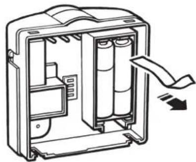
| Power Supply 2 x AA/MN1 | 500 alkaline batteries |
| Control Pollution Situation | Degree 2 |
| Rated Impulse Voltage 2.5 kV |
| Designed to meet BS EN 6 | 0730-2-9 (EN 300220 for RF) |
| Ball Pressure Test 75°C | |
| Temperature Range 5-30°C |
| Dimensions (mm) 85 wide | x 86 high x 42 deep |
Important note RF products: Ensure that there are no large metal objects, such as boiler cases or other large appliances, in line of sight between the transmitter and receiver as these will prevent communication between thermostat and receiver.

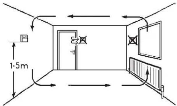
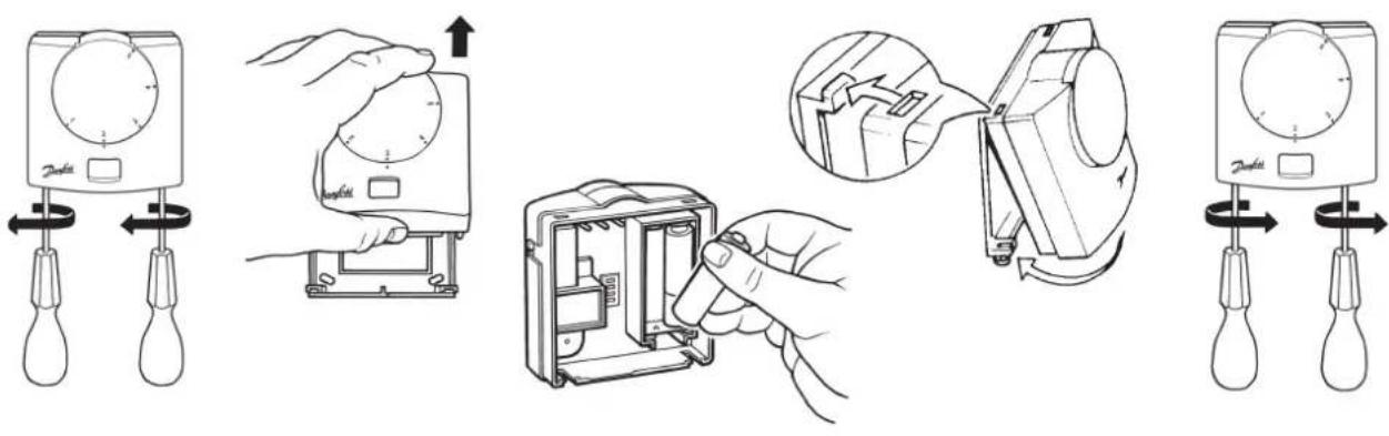
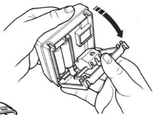
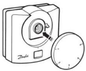
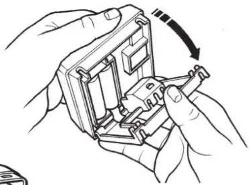
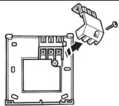
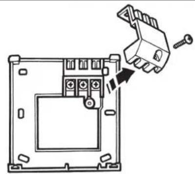
Mounting
Installation Instructions
Fix at a height of 1.5m approx from the floor, away from draughts or heat sources such as radiators, open fires or direct sunlight.
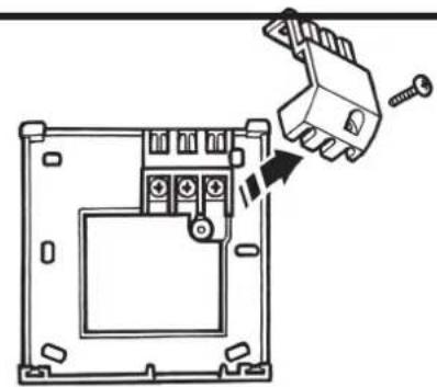
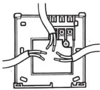
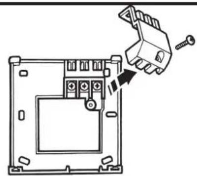
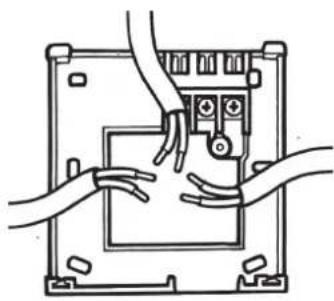
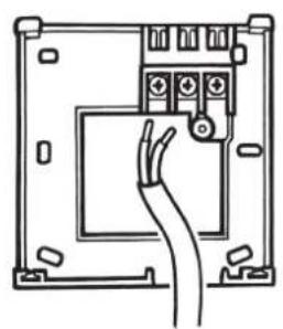
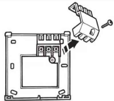
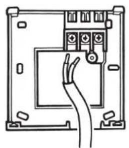
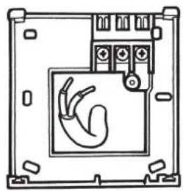
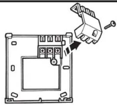
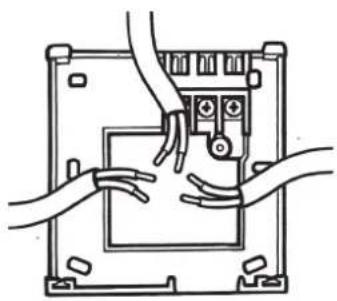
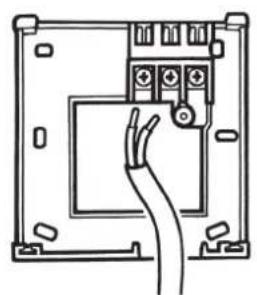
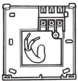
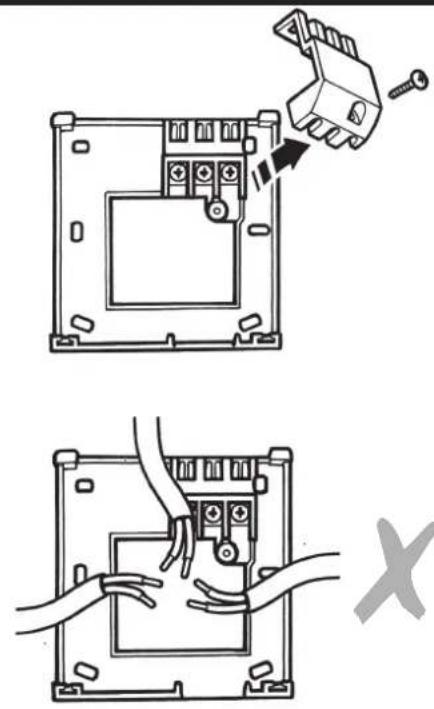
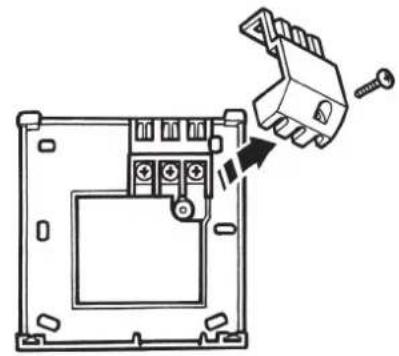
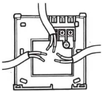
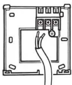
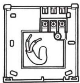
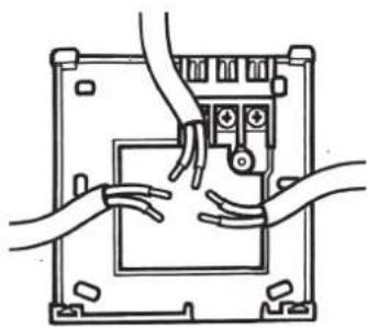
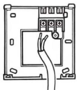
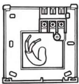
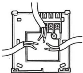
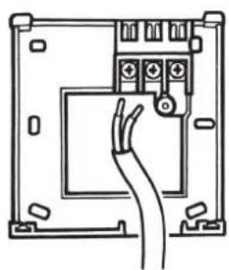
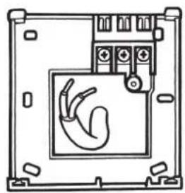
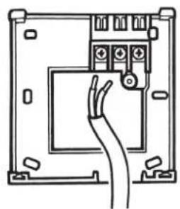
Wiring (not RF models)
GB

HEATING
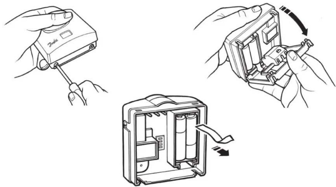
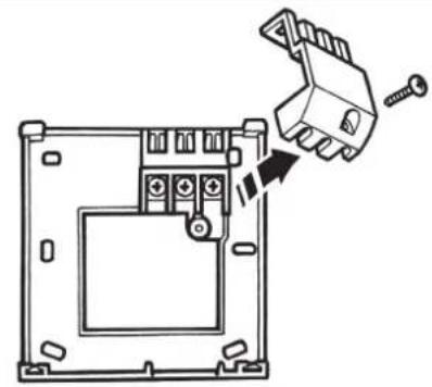
natural_image
Diagram of a device mounting bracket with a hand inserting a small component (no text or symbols)
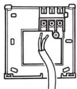
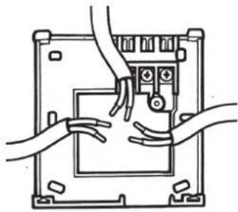
natural_image
Line drawing of hands connecting a device panel to a control panel (no text or symbols)

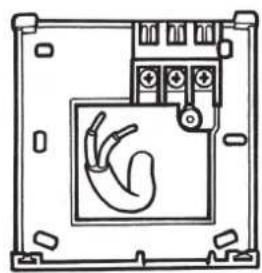
natural_image
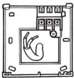
Line drawing of an electrical panel with a cable inserted into the socket (no text or symbols)
natural_image
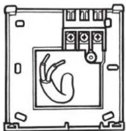
Technical line drawing of a device enclosure with a hand symbol inside (no text or labels)

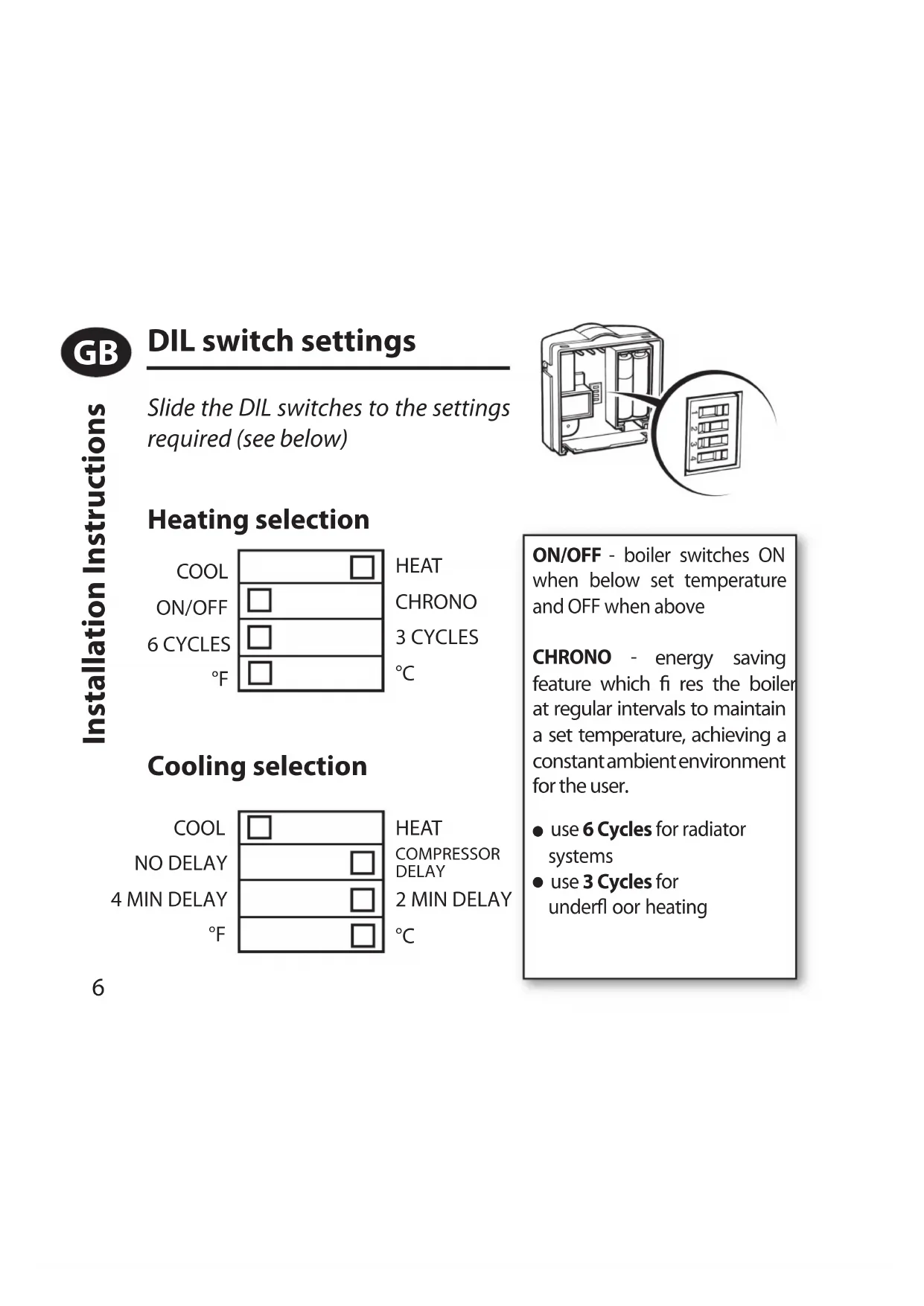
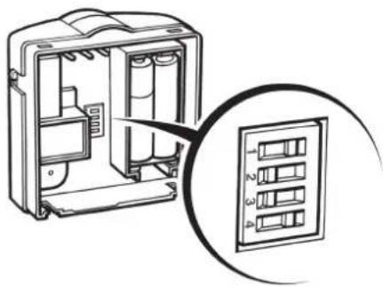
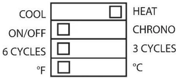
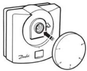
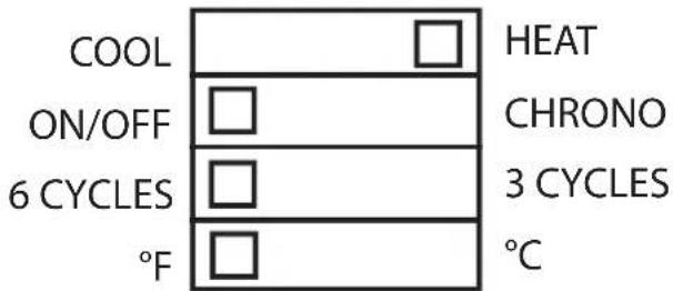
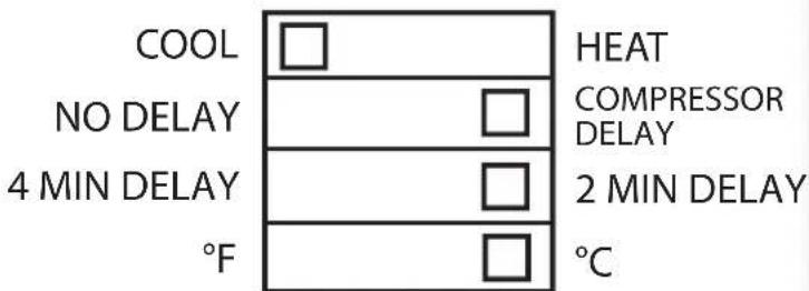
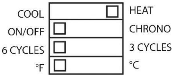
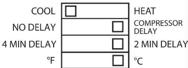
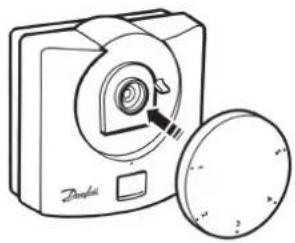
DIL switch settings
Slide the DIL switches to the settings required (see below)
natural_image
Diagram of an electrical enclosure with internal components and a close-up view of the internal panel (no text or symbols)
Heating selection
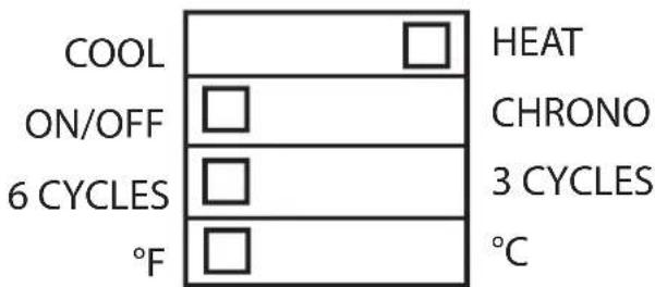
Cooling selection
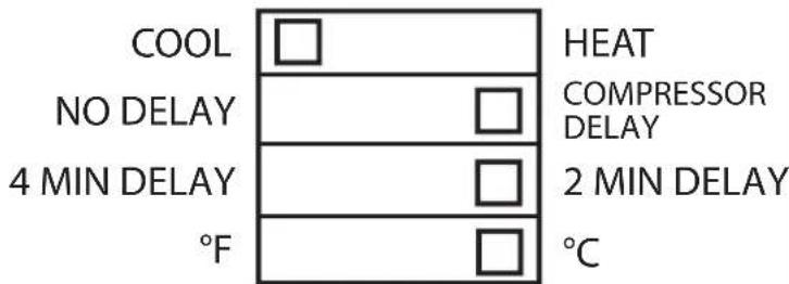
ON/OFF - boiler switches ON when below set temperature and OFF when above
CHRONO - energy saving feature which fi res the boiler at regular intervals to maintain a set temperature, achieving a constant ambient environment for the user.
● use 6 Cycles for radiator systems
- use 3 Cycles for underfl oor heating
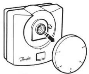
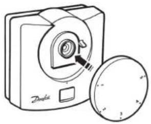
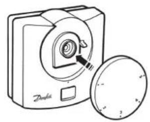
Locking & Limiting
GB
natural_image
Line drawing of a portable device with a circular button and a lid, no text or symbols present
natural_image
Line drawing of a digital camera with a circular button and a magnified inset showing the lens (no text or symbols)


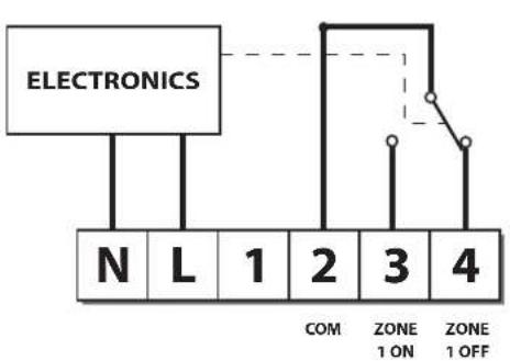
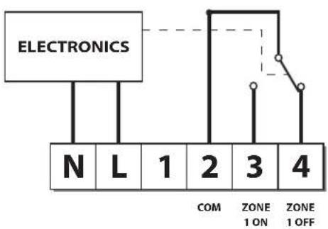
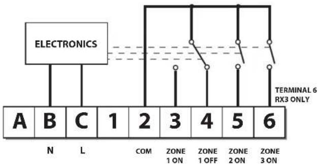
Receiver Wiring (RF only)
RX1 RX2 and RX3
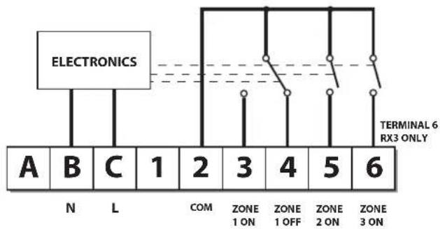
flowchart
graph TD
    A["Electronics"] --> B["A"]
    A --> C["B"]
    A --> D["C"]
    A --> E["1"]
    A --> F["2"]
    A --> G["3"]
    A --> H["4"]
    A --> I["5"]
    A --> J["6"]
    K["N"] --> L["L"]
    M["COM"] --> N["ZONE 1 ON"]
    O["ZONE 1 OFF"] --> P["ZONE 2 ON"]
    Q["ZONE 3 ON"] --> R["ZONE 6 RX3 ONLY"]
Note: 1) For mains voltage operated systems, link terminal 2 to mains live supply
2) Power supply to unit must not be switched by timeswitch

Commissioning (RF only)
If the thermostat and the receiver have been supplied together in a combined pack, the units have been paired in the factory and no commissioning is required (RX1 only).
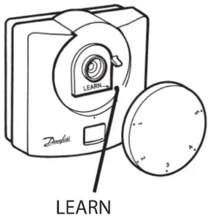
Step 1 RET B-RF
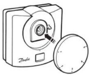
Position the setting dial to number 1. Remove dial, press & hold LEARN button for 3 seconds (located under setting dial).
Do not replace the setting dial yet
NOTE: Thermostat now transmits signal continuously for 5 mins.
Step 2 RX1
Press and hold buttons PROG and CH1 until green light fl ashes.
Step 3 RX2/RX3
For RX2 or RX3 repeat steps 1 and 2 for each thermostat and channel, leaving at least 5 mins between the commissioning of each thermostat.
Step 4 RET B-RF
To replace the thermostat setting dial, position the dial to number 1.


What is a room thermostat?
... an explanation for householders. A room thermostat simply switches the heating system on and off as necessary. It works by sensing the air temperature, switching on the heating when the air temperature falls below the thermostat setting, and switching it off once this set temperature has been reached.
Turning a room thermostat to a higher setting will not make the room heat up any faster. How quickly the room heats up depends on the design of the heating system, for example, the size of boiler and radiators.
Neither does the setting affect how quickly the room cools down. Turning a room thermostat to a lower setting will result in the room being controlled at a lower temperature, and saves energy.
The heating system will not work if a timeswitch or programmer has switched it off.
The way to set and use your room thermostat is to find the lowest temperature setting that you are comfortable with, and then leave it alone to do its job. The best way to do this is to set the room thermostat to a low temperature – say 18°C – and then turn it up by one degree each day until you are comfortable with the temperature. You won’t have to adjust the thermostat further. Any adjustment above this setting will waste energy and cost you more money.
If your heating system is a boiler with radiators, there will usually be only one room thermostat to control the whole house. But you can have different temperatures in individual rooms by installing thermostatic radiator valves (TRVs) on individual radiators. If you don't have TRVs, you should choose a temperature that is reasonable for the whole house. If you do have TRVs, you can choose a slightly higher setting to make sure that even the coldest room is comfortable, then prevent any overheating in other rooms by adjusting the TRVs.
Room thermostats need a free flow of air to sense the temperature, so they must not be covered by curtains or blocked by furniture. Nearby electric fires, televisions, wall or table lamps may prevent the thermostat from working properly.

User Instructions
Display
The LCD displays actual room temperature until the setting dial is moved.
Setting the temperature
Turn setting dial to required temperature. The selected temperature will flash in the LCD to signify it is showing set temperature.
After a short period the display stops flashing and shows actual room temperature.
Thermostat status (heat mode only)
A flame symbol will be lit whenever the thermostat is calling for heat.
Thermostat status (cool mode only)
A snowfl ake symbol will be lit whenever the thermostat is calling for cooling. If this is seen to flash, the thermostat output is delayed for a short period to prevent compressor damage.
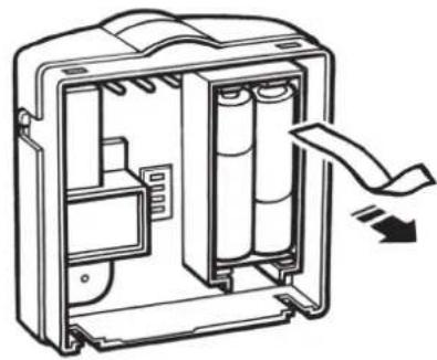
Low battery indication
A battery symbol will flash in the display when batteries require replacement. Batteries should be replaced within 15 days, after which the thermostat will turn off the load it is controlling. When this happens "Of" will be displayed.
IMPORTANT: alkaline batteries must be used.

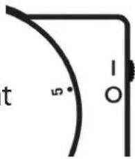
RET B-LS model only
This model is fitted with an Auto/Off switch.
When the switch is set in "I" position the thermostat controls at the temperature set by the setting dial.
When set to "O" the thermostat output is turned off and "Of" is displayed.
RET B-NSB model only
This model is fitted with a Day/Night switch.
When the switch is set to the "Sun Symbol", the thermostat controls at the temperature set by the setting dial.
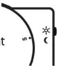
When set to the "Moon symbol", the thermostat controls at 4°C below the temperature set by the setting dial.
NOTE: if used to control cooling, thermostat controls 4°C higher, with switch in MOON position.
natural_image
Line drawing of hands using a tool to adjust or install a device (no text or symbols visible)
natural_image
Illustration of hands assembling a mechanical component with a curved arrow indicating rotation (no text or symbols)
natural_image
Diagram of a device casing with internal components and a scroll arrow indicating motion (no text or symbols)
HEATING
natural_image
Diagram of a mechanical component with a tool interacting with it, showing a bracket and mounting base (no text or symbols)
natural_image
Line drawing of hands connecting a device panel to a control panel (no text or symbols)
natural_image
Line drawing of an electrical connector with a cable inserted, no text or symbols present

natural_image
Diagram of a medical device with a hand symbol inside, no text or labels present
F
natural_image
Technical line drawing of an electrical enclosure with internal components and a close-up inset showing labeled compartments (no text or symbols present)
natural_image
Illustration of a digital camera with a magnifying glass and a circular lens (no text or symbols)
natural_image
Line drawing of a compact digital camera with a circular button and a magnified inset showing the lens (no text or symbols)


natural_image
Illustration of a Danish digital camera with a circular lens and a separate circular button (no text or symbols)
LEARN
natural_image
Simple line drawing of a curved bracket with a labeled angle (5° and 1°) and a vertical line, no text or symbols present.
natural_image
Simple line drawing of a corner with a curved line and sun icon, no text or symbols present
installationsanwei sungen
AUS
EIN
COM
HEIZUNG
natural_image
Technical line drawing of a mechanical component with a bracket and mounting holes, showing a close-up view of the part (no text or symbols present)

natural_image
Illustration of hands connecting a device panel to a control panel (no text or symbols visible)
natural_image
Line drawing of an electrical enclosure with a cable inserted into the main panel (no text or symbols)
natural_image
Technical line drawing of a device enclosure with internal components and a hand symbol (no text or labels)
Einstellungen
natural_image
Technical line drawing of an electrical enclosure with internal components and a close-up inset showing internal panel layout (no text or symbols)
natural_image
Illustration of a portable digital camera with a circular lens and padlock, alongside a circular dial indicator (no text or symbols)

natural_image
Line drawing of a portable digital camera with a circular lens and a square button, no text or symbols present.
natural_image
Line drawing of a digital camera with a circular lens and a separate circular button (no text or symbols)
LEARN
Nur RET B-LS-Modell
CALEFACCION
natural_image
Technical line drawing of a mechanical component with a bracket and mounting holes, showing a close-up view of the component (no text or symbols)
natural_image
Line drawing of hands installing or adjusting a component on an electronic device casing (no text or symbols)
natural_image
Line drawing of an electrical connector with a cable inserted (no text or symbols)
natural_image
Diagram of a medical device with a heart symbol inside, enclosed in a rectangular frame (no text or labels)
ES
Ajustes del instalador
natural_image
Diagram of an electrical enclosure with internal components and a close-up view of the internal panel (no text or symbols)
Calefacción
Refrigeración

natural_image
Line drawing of a compact digital camera with a circular lens and a lid, no text or symbols present
natural_image
Illustration of a portable digital camera with a circular lens and a separate circular button (no text or symbols)


natural_image
Line drawing of a digital camera with a circular base and a magnified inset showing the lens (no text or symbols)
LEARN
natural_image
Simple line drawing of a curved bracket with a labeled angle (5° and 1°) and a vertical line (no text or symbols beyond basic geometry)
Solo modelo RET B-NSB
HEATING
natural_image
Line drawing of an electrical connector with a cable inserted, no text or symbols present
natural_image
Technical line drawing of a device casing with internal components and a hand symbol (no text or labels)
Montørindstillinger
natural_image
Diagram of an electrical enclosure with internal components and a magnified inset showing four labeled panels (no text or symbols present)

1) ON/OFF - kedlen er ON, når temperaturen er under den indstillede temperatur, og OFF, når temperaturen er over den indstillede temperatur
natural_image
Illustration of a portable device with a circular lid, a shield, and a lock icon (no text or symbols)
natural_image
Line drawing of a portable digital camera with a circular base and a magnified inset showing the lens (no text or symbols)
Low battery indication

Type RET B-LS
natural_image
Simple line drawing of a corner with a 5-degree angle and a vertical line marked '1-O' (no text or symbols beyond basic geometry)
Type RET B-NSB
HEATING

natural_image
Diagram of a mechanical component with a tool interacting with it, showing a bracket and mounting base (no text or symbols)

natural_image
Line drawing of hands connecting a device panel to a control panel (no text or symbols)

natural_image
Line drawing of an electrical connector with a cable inserted, no text or symbols present

natural_image
Diagram of a medical device with internal organ outline and electrical components (no text or labels)

Instellingen
natural_image
Diagram of an electrical enclosure with internal components and a magnified inset showing four labeled compartments (no text or symbols present)
Verwarmen
Koelen
natural_image
Illustration of a digital camera with a magnified inset showing its internal components (no text or symbols)

natural_image
Line drawing of a compact digital camera with a circular lens and a separate circular base (no text or symbols)
Stap 2 RX1 - Druk binnen 5 minuten na
natural_image
Simple line drawing of a corner with a curved line and sun icon, no text or symbols present
Ovly's evictorations
Θέρμανση
natural_image
Technical line drawing of a mechanical component with a hand holding a tool (no text or symbols)
natural_image
Diagram of hands connecting a device panel to a control panel (no text or symbols visible)
natural_image
Line drawing of an electrical connector with a cable inserted, no text or symbols present
natural_image
Technical line drawing of a mechanical or electrical component with internal components and a central hand symbol (no text or labels)
natural_image
Diagram of an electrical enclosure with internal components and a magnified inset showing four labeled panels (no text or symbols present)

natural_image
Illustration of a digital camera with a rotary dial and a padlock, alongside a circular button symbol (no text or labels)

natural_image
Line drawing of a compact digital camera with a circular lens and lid (no text or symbols)

natural_image
Line drawing of hands using a handheld device to switch a cable (no text or symbols present)
natural_image
Illustration of hands assembling a mechanical component with a curved arrow indicating rotation (no text or symbols)
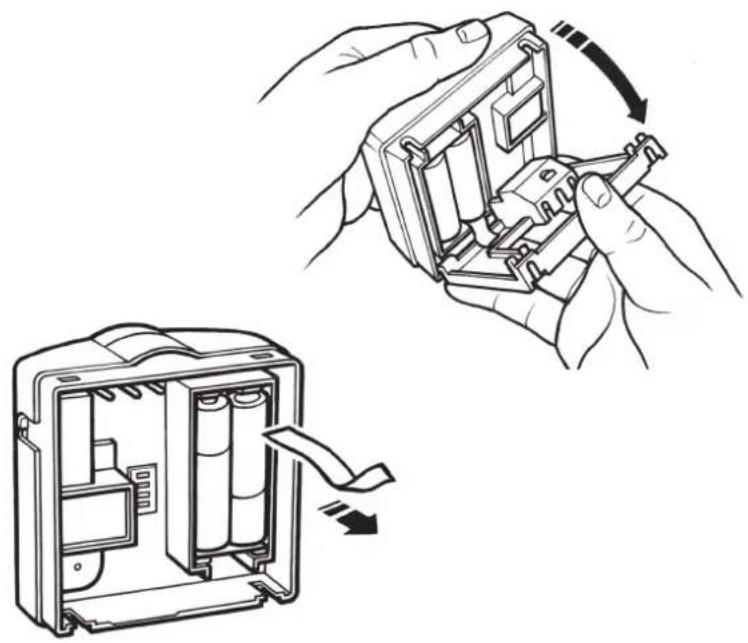
natural_image
Diagram of an open battery pack with internal compartments and a directional arrow indicating flow (no text or symbols)
HEATING
natural_image
Technical line drawing of a mechanical component with a bracket and mounting base (no text or symbols)
natural_image
Line drawing of hands connecting a device panel to a control panel (no text or symbols)
natural_image
Line drawing of an electrical panel with a cable inserted into the socket (no text or symbols)
natural_image
Technical line drawing of a device enclosure with a hand symbol inside (no text or labels)

natural_image
Diagram of an electrical enclosure with internal components and a close-up view of the internal panel (no text or symbols)
Tryb - grzanie
Chłodzenie
Tryb ON/OFF (WŁ./WYŁ.)
natural_image
Illustration of a portable device with a circular lid, a shield, and a padlock (no text or symbols)

natural_image
Line drawing of a compact digital camera with a circular lens and a separate flat case (no text or symbols)
Montavimo instructicios
Šildymo
natural_image
Technical line drawing of a mechanical component with a hand inserting a pin (no text or symbols)
natural_image
Illustration of hands installing or adjusting a component on a device casing (no text or symbols visible)
natural_image
Simple line drawing of an electrical connector with a cable inserted (no text or symbols)
natural_image
Technical line drawing of a mechanical or electrical component with internal components and a central schematic symbol (no text or labels)
DIL jungiklio nustatymai
natural_image
Simple diagram with three horizontal lines and four empty squares, no text or symbols present
Karštis
Chrono
3 ciklai
°C
natural_image
Simple diagram with four horizontal lines and four empty squares, no text or symbols present.
Karštis
natural_image
Diagram of an electrical enclosure with internal components and a magnified inset showing internal panel layout (no text or symbols)
natural_image
Illustration of a portable camera with a scroll wheel, a circular lid, and a padlock (no text or symbols)
natural_image
Line drawing of a compact digital camera with a circular lens and a lid, no text or symbols present
Imtuvo laidai (tik RF modeliams)
RX1 RX2 & RX3
flowchart
graph TD
    A["Electronics"] --> B["A"]
    A --> C["B"]
    A --> D["C"]
    A --> E["1"]
    A --> F["2"]
    A --> G["3"]
    A --> H["4"]
    A --> I["5"]
    A --> J["6"]
    K["N"] --> L["L"]
    M["COM"] --> N["ZONE 1 ON"]
    O["ZONE 1 OFF"] --> P["ZONE 2 ON"]
    Q["ZONE 3 ON"] --> R["ZONE 3 ON"]
    S["TERMINAL 6 RX3 ONLY"] -.-> T["Terminal 6 RX3 ONLY"]
Tik RET B-LS modelis
natural_image
Simple line drawing of a corner with a curved line and a star symbol (no text or labels)
natural_image
Line drawing of hands using a tool to adjust or install a device (no text or symbols visible)
natural_image
Illustration of hands installing or adjusting a battery pack into an open circuit board (no text or symbols present)
HEATING
natural_image
Diagram of a mechanical component with a hand inserting a pin into a housing (no text or symbols)
natural_image
Line drawing of hands installing or adjusting a component on an electronic device (no text or symbols)
natural_image
Line drawing of an electrical panel with a cable inserted into the socket (no text or symbols)
natural_image
Diagram of a medical device with a hand symbol inside, no text or labels present

natural_image
Diagram of an electrical enclosure with internal components and a close-up view of the internal panel (no text or symbols)
natural_image
Illustration of a portable device with a circular lid, a shield, and a padlock (no text or symbols)
natural_image
Line drawing of a compact digital camera with a circular lens and a separate flat case (no text or symbols)
natural_image
Line drawing of a Densell digital camera with a circular button and a pointer, no text or symbols present.
LEARN
Solo modello RET B-LS
www.danfoss.com/BusinessAreas/Heating
This product complies with the following EC Directives:
Electro-Magnetic Compatibility Directive.
(EMC) (89\336\EEC), (92\31\EEC)
Low Voltage Directive.
(LVD) (73\23\EEC), (93\68\EEC)

Part No 25693v09 07/07