KEOR LP - Inverter LEGRAND - Free user manual and instructions
Find the device manual for free KEOR LP LEGRAND in PDF.



| Product Type | Double conversion online UPS |
| Brand | Legrand |
| Model | KEOR LP |
| Rated Power | 1000 VA / 2000 VA / 3000 VA depending on model |
| Input Voltage | 230 V AC |
| Output Voltage | 230 V AC |
| Battery Type | Sealed lead-acid, 12 x 7 Ah |
| Battery Voltage | 24 V DC (1000 VA), 48 V DC (2000 VA), 72 V DC (3000 VA) |
| Dimensions (W x D x H) | 322 x 151 x 444 mm |
| Weight | 39 kg |
| Operating Temperature | 0 to 40 °C |
| Operating Humidity | 30 to 90 % non-condensing |
| Protection | Overcurrent circuit breaker, anti-interference filter, voltage regulation |
| Connectivity | Mains input, UPS output, DC connector for external battery |
| Cooling | Natural ventilation, keep air vents clean |
| Maintenance | Recharge battery every 2-3 months if unused; battery replacement by technician |
| Cleaning | Clean air vents with a dry cloth; do not use liquid |
| Safety | Mandatory grounding; do not open battery; wear insulated gloves |
| Spare Parts | Batteries of same type and quantity; DC cables optional |
| Repairability | Service by qualified technician only; no user-serviceable parts |
| Warranty | Standard manufacturer warranty (void if unauthorized opening) |
Frequently Asked Questions - KEOR LP LEGRAND
User questions about KEOR LP LEGRAND
0 question about this device. Answer the ones you know or ask your own.
Ask a new question about this device
Download the instructions for your Inverter in PDF format for free! Find your manual KEOR LP - LEGRAND and take your electronic device back in hand. On this page are published all the documents necessary for the use of your device. KEOR LP by LEGRAND.
USER MANUAL KEOR LP LEGRAND
natural_image
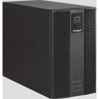
Black battery bank labeled 'legrand' with visible ventilation grille and control panel (no additional text or symbols)KEOR LP BATTERY BANK 1, 2, 3 kVA
FR
FRANÇAIS
3FRANÇA
EN
ENGLISH
13
IT
ITALIANO
19
DE
DEUTSCH
27
ES
ESPAÑOL
35
NL
NEDERLANDS
43
KEOR LP BATTERY BANK 1, 2, 3 kVA
R
Index
Risk of Electric Shock the Battery Circuit is not isolated from AC, hazardous Voltage may exist between battery terminals and ground. Test before touching with bare hands.

ATTENTION
flowchart
graph TD
    A["Switch with 3-pin connector"] --> B["Switch connected to terminal block"]
    B --> C["Switch with cable and wire"]
    C --> D["Terminal block with cable and wire"]
Recycling the Used battery

Contact your local recycling or hazardous waste center for information on proper disposal of the used battery.
KEOR LP BATTERY BANK 1, 2, 3 kVA
Index
1 Introduction 12
2 Condition of use 12
3 Rear Panel 15
4 Installation 16
5 Technical features 18
This manual contains information for users of the Keor LP battery banks designed for the Keor LP 1,2,3 kVA UPS models.
You are advised to read carefully this handbook and the safety instruction sheet included in the packaging before installing your uninterruptible power supply, meticulously following the instructions given herein.
In case of problems with the UPS, please read this manual before contacting technical support; Please download the latest version of the manual from the web site www.ups.legrand.com.
2 Condition of use
- The battery bank is supplied with a factory input plug and can be safely connected to the wall receptacle by the user.
- This battery bank is connected to an UPS. There will be voltage at the output terminals if the UPS is turned on even if the input AC Mains is not available.
- Make sure that the AC Utility outlet is correctly grounded.
- Do not try to repair the unit by yourself, contact your local supplier or your warranty will be void.
- Use a certified input power cable with the correct plugs and sockets for the appropriate voltage system.
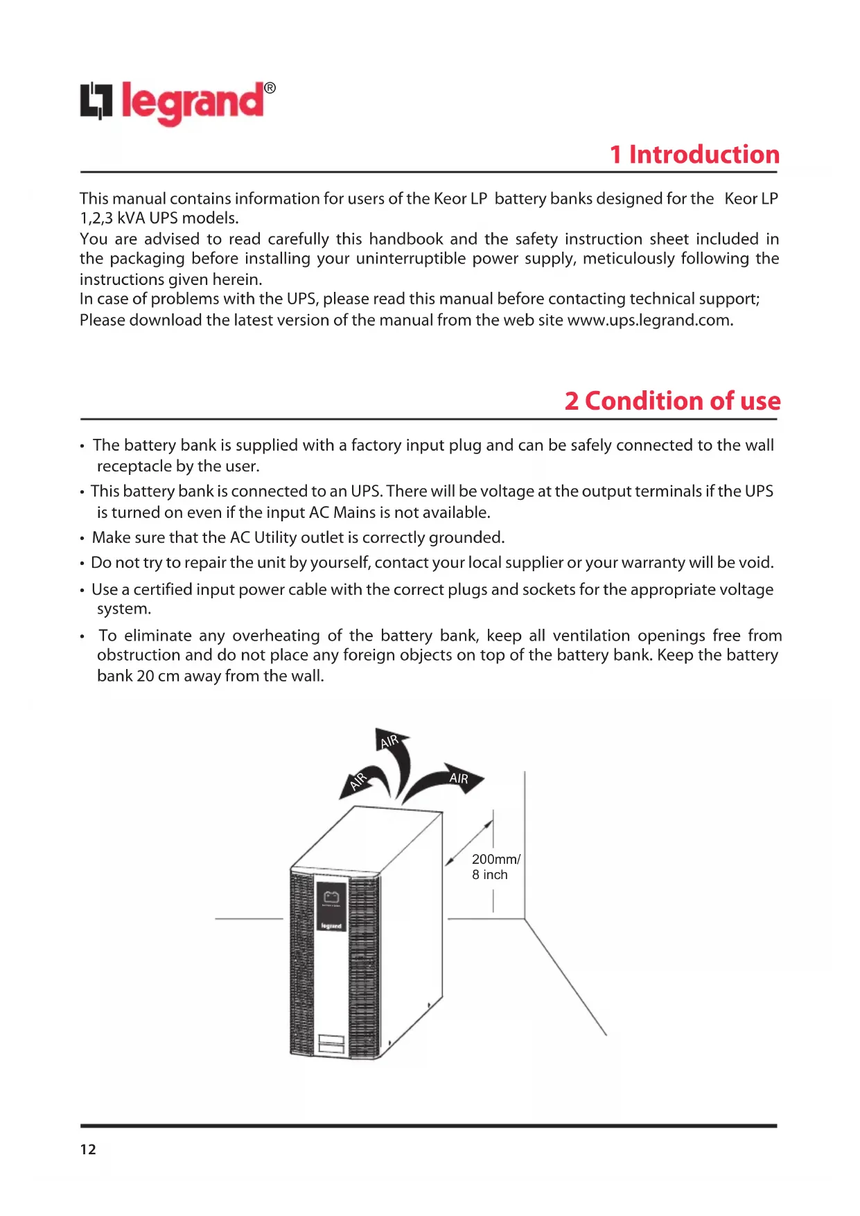
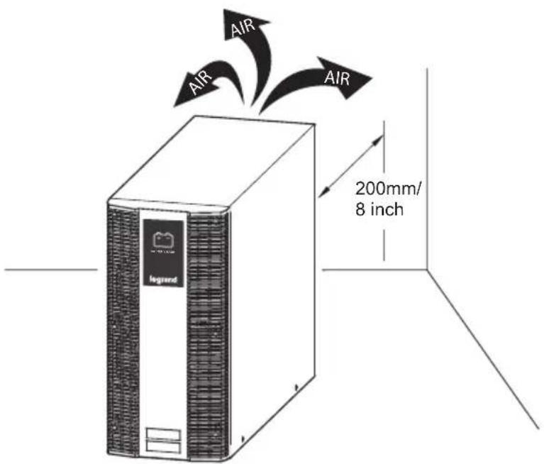
- To eliminate any overheating of the battery bank, keep all ventilation openings free from obstruction and do not place any foreign objects on top of the battery bank. Keep the battery bank 20 cm away from the wall.
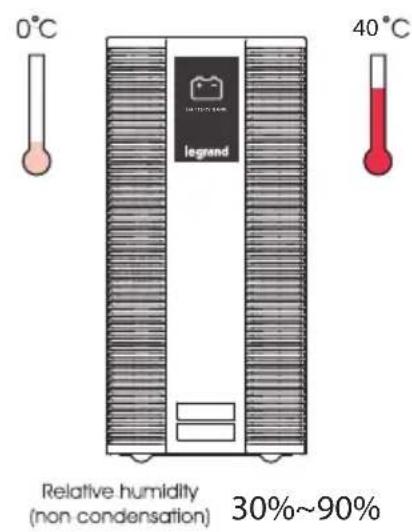
- Make sure the battery bank is installed within the proper environment as specified. (0-40°C and 30-90% non-condensing humidity)
- Do not install the battery bank under direct sunlight. Your warranty will be void if the batteries fail due to overheating.
• This battery bank is designed for indoor use only. - This battery bank is not designed for use in dusty, corrosive and salty environment.
- The warranty for this battery bank will be void if water or other liquid is spilt or poured directly onto the battery bank. Similarly we do not warrant any damage to the battery bank if foreign objects are deliberately or accidentally inserted into the battery bank enclosure.
- The battery will discharge naturally if the system is unused for a period of time.
- It should be recharged every 2-3 months if unused. During normal operation, the batteries will be automatically remained in charged condition.
- When Replacing Batteries, Replace With the Same Quantity, Type & Capacity.

CAUTION
vicing of Batteries Should be Performed or Supervised by Trained Personnel with Knowledge of Batteries and the Required Precautions

CAUTION
Not Dispose of Battery or Batteries in an open fire. The Battery May Explode.

CAUTION
Do not open or mutilate the batteries. The electrolyte from the batteries is toxic and harmful to the skin and eyes.

CAUTION
Risk of Electric Shock the Battery Circuit is not isolated from AC, hazardous Voltage may exist between battery terminals and ground. Test before touching with bare hands.

CAUTION
A Battery can present a Risk of Electrical Shock and High Short Circuit Current. The Following Precaution Should be Observed When Working on Batteries:
A. Remove watches, rings, or other metal objects.
B. Use tools with insulated handles.
C. Wear rubber gloves and boots.
D. Do not lay tools or metal parts on top of batteries.
E. Disconnect charging source prior to connecting or disconnecting battery terminals.
Storage Instruction
For extended storage through moderate climate(-15 to +30 °C / +5 to +86 °F), the batteries should be charged for 12 hours every 6 months by plugging the UPS power cord into the wall receptacle. Repeat this every 3 months under high temperature (+30 to +45 °C / +86 to +113 °F) environment.
3 Rear Panel
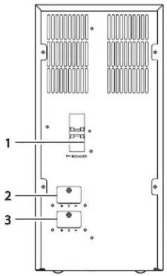
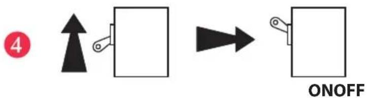
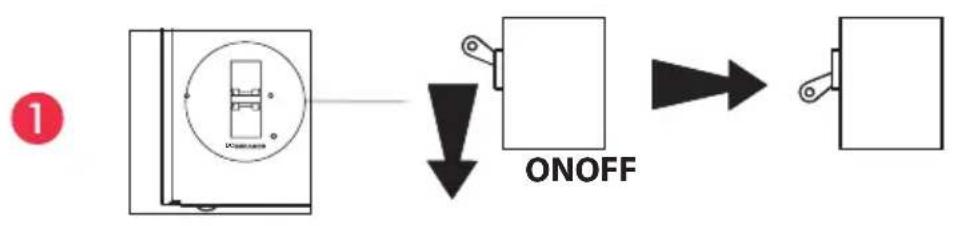
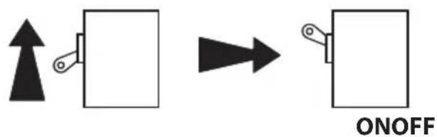
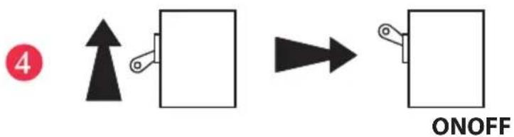
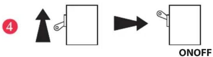
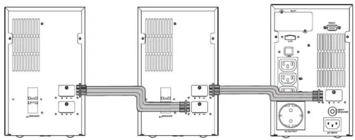
| 1. DC Breaker | 1. Battery Over-current Protection Breaker2. To easy swappable battery, please put the position of the breaker in “O” position. In case there is 2nd(or next) battery bank connected with the battery bank, the DC voltage from the UPS Bat.+/- will flow through without any interruption to the 2nd Battery Bank. |
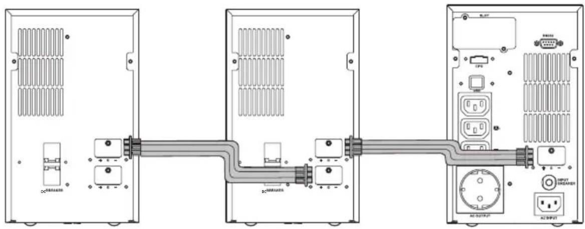
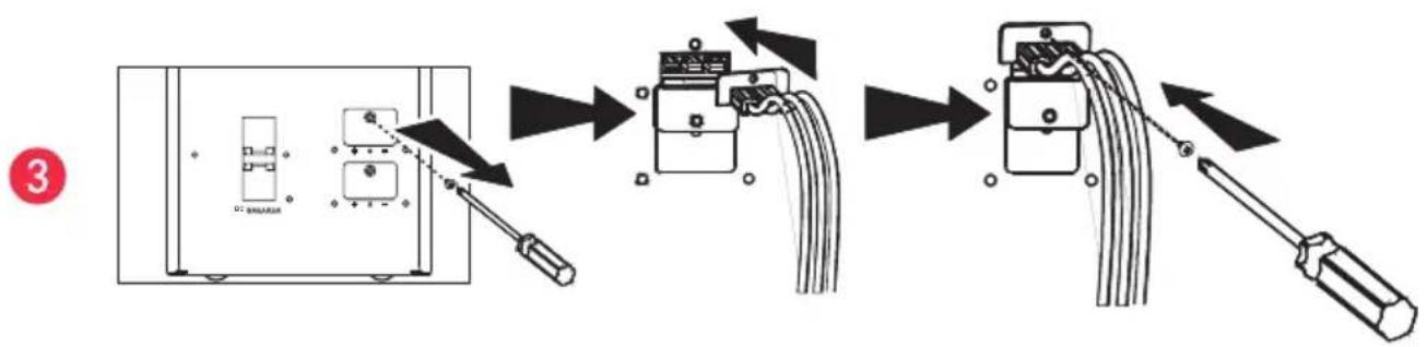
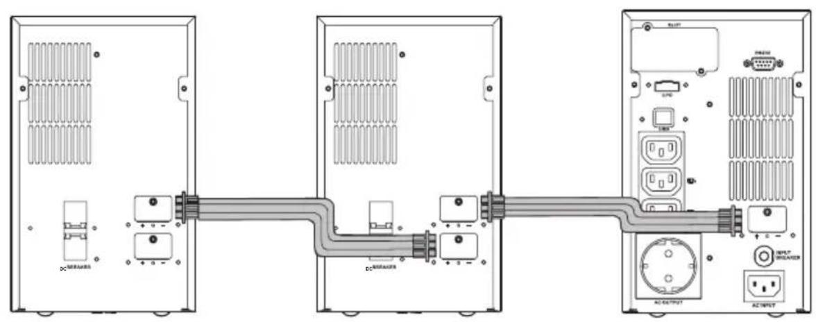
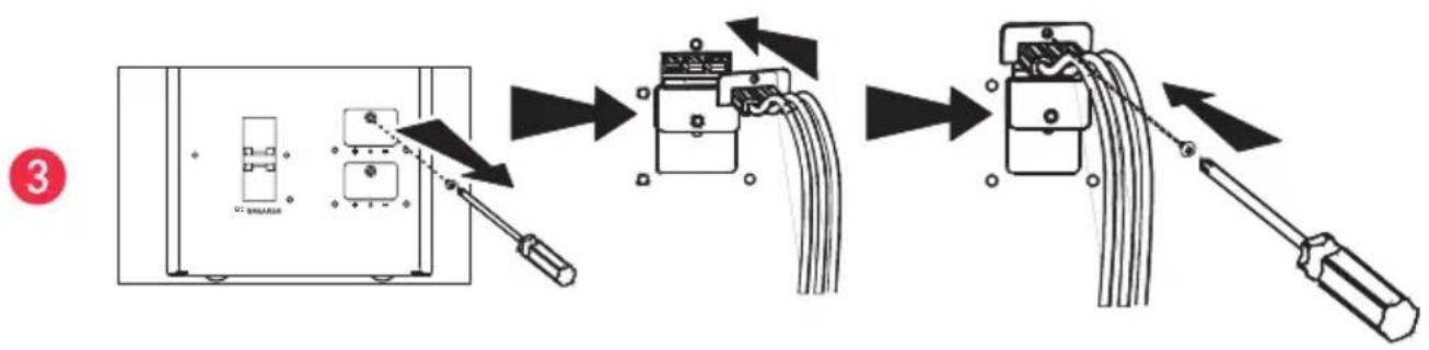
| 2. UPS BAT. +/- To the UPS DC Connected | |
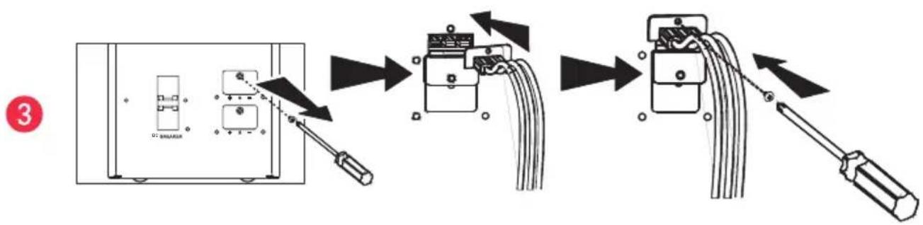
| 3. EXT.BAT. +/- To the DC connected of the 2nd(or next) battery bank connected. | |
Note: The packing condition and the external outlook of the unit should be inspected carefully before installation. Retain the packing material for future use.
Unpacking
- Take the battery bank out of the PE foam.
- Remove the packing materials.
Note: The battery bank module is approx. 39kg, be cautious when unpacking and lifting the unit to avoid injury.
- Standard Package includes:
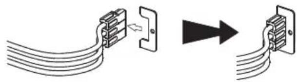
a. DC connect cable
b. User's Manual
- Accessories for Tower Mount
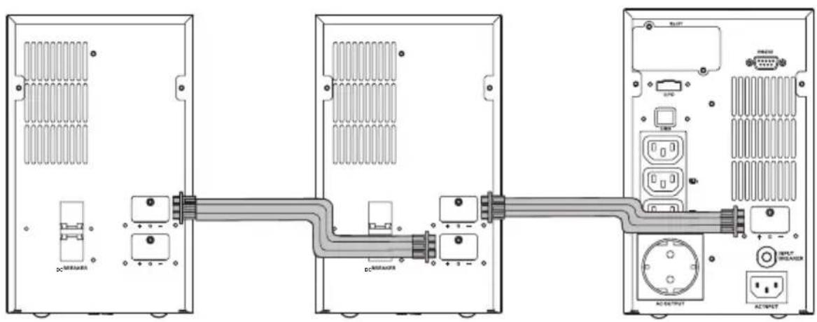
| UPS Connection | |
| AS 3000 230VAS 2000 230VAS 1000 230V | 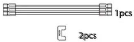 |
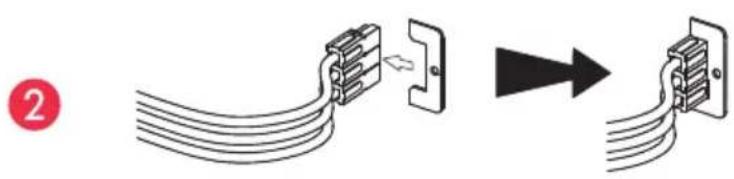
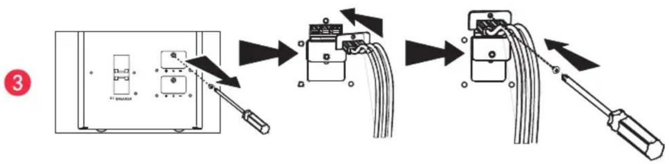
Installation Instructions
flowchart
graph TD
    A["Start"] --> B["ON/OFF"]
    B --> C["Next Step"]
    style A fill:#f9f,stroke:#333
    style B fill:#ccf,stroke:#333
    style C fill:#cfc,stroke:#333
flowchart
graph TD
    A["Switch with 3-pin connector"] --> B["Switch connected to terminal block"]
    B --> C["Switch with cable and wire"]
    C --> D["Terminal block with cable and wire"]
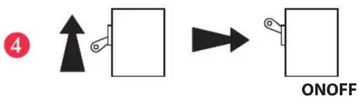
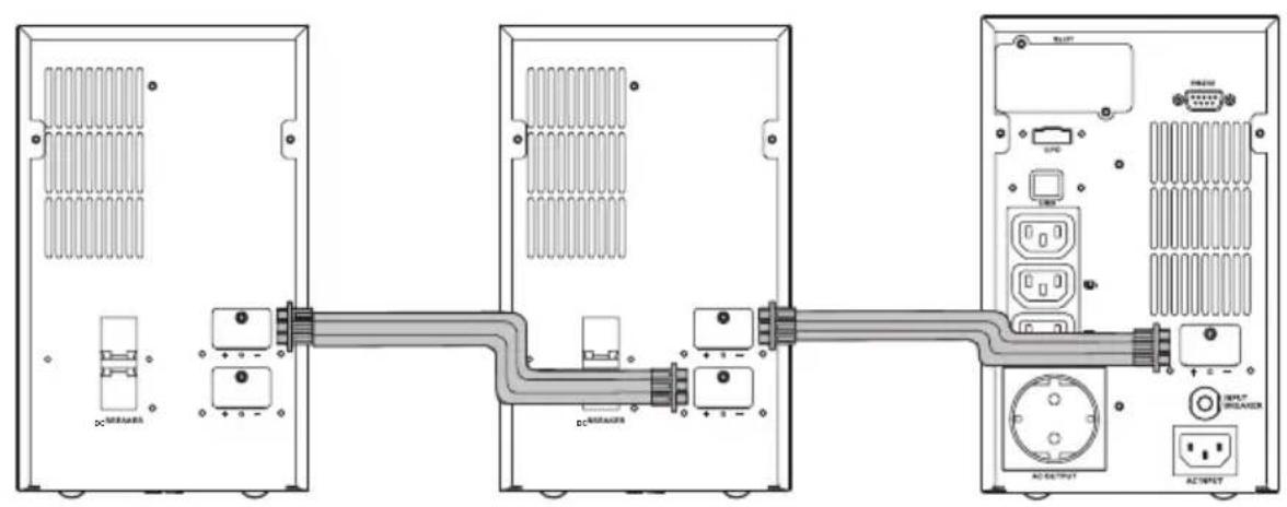
| UPS 1000VA 2000VA 3000VA | |||
| Battery Bank PN 310598 310599 310600 | |||
| Nominal System Voltage 24VDC 48VDC 72VDC | |||
| Battery Quantity 12 12 12 | |||
| Battery Type 7Ah 7Ah 7Ah | |||
| Connector color Red (+), Black (−), Green(Gnd) | |||
| Dimensions, W x D x H, in (mm) | |||
| Unit | 322 x 151 x 444 | ||
| Weight (kg) | |||
| Unit | 39 | ||
Recycling the Used battery

Contact your local recycling or hazardous waste center for information on proper disposal of the used battery.
KEOR LP BATTERY BANK 1, 2, 3 kVA
Indice
flowchart
graph TD
    A["Switch with 3-pin connector"] --> B["Switch connected to terminal block"]
    B --> C["Switch with cable and wire"]
    C --> D["Terminal block with cable and wire"]
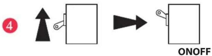
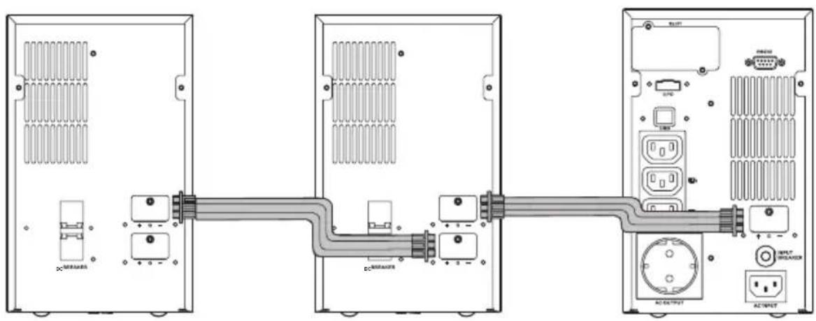
flowchart
graph TD
    A["Device with circular component"] --> B["ON/OFF"]
    B --> C["Switch"]
2
natural_image
Diagram showing cable connection to a connector with an arrow indicating direction (no text or symbols present)3

4
flowchart
graph TD
    A["Switch with 3-pin connector"] --> B["Switch connected to terminal block"]
    B --> C["Terminal block with cable and wire"]
    C --> D["Terminal block with cable and wire connected to terminal block"]
flowchart
graph TD
    A["Switch with 3-pin connector"] --> B["Switch with cable"]
    B --> C["Terminal Block with cable and wire"]
    C --> D["Terminal Block with cable and wire connected via cable to terminal block"]
Pro and Consumer Service
BP 30076 - 87002
LIMOGES CEDEX FRANCE
www.legrand.com
Brand : LEGRAND
Model : KEOR LP
Category : Inverter