TS 142L - Riding mower HUSQVARNA - Free user manual and instructions
Find the device manual for free TS 142L HUSQVARNA in PDF.
| Features | Details |
|---|---|
| Product type | Garden tractor |
| Engine | Husqvarna engine, 500 cc |
| Power | 15.5 kW at 3,600 rpm |
| Transmission | Automatic transmission |
| Cutting width | 107 cm |
| Cutting height | 25 to 75 mm, adjustable |
| Tank capacity | 6.5 liters |
| Front tires | 15 x 6 inches |
| Rear tires | 20 x 8 inches |
| Weight | 220 kg |
| Usage | Ideal for maintaining medium to large lawns and gardens |
| Maintenance | Regularly check oil and fuel levels, clean the cutting deck |
| Safety | Recommended safety equipment: goggles, gloves, safety shoes |
| Warranty | 2 years, warranty conditions to be checked at purchase |
Frequently Asked Questions - TS 142L HUSQVARNA
User questions about TS 142L HUSQVARNA
0 question about this device. Answer the ones you know or ask your own.
Ask a new question about this device
Download the instructions for your Riding mower in PDF format for free! Find your manual TS 142L - HUSQVARNA and take your electronic device back in hand. On this page are published all the documents necessary for the use of your device. TS 142L by HUSQVARNA.
USER MANUAL TS 142L HUSQVARNA
natural_image
Silhouette of a person riding an electric scooter (no text or symbols)TS142L
EN Operator's manual 2-41
| Introduction | 2 |
| Safety | 6 |
| Assembly | 10 |
| Operation | 14 |
| Maintenance | 18 |
| Troubleshooting | 31 |
| Transportation, storage and disposal | 35 |
| Storage | 36 |
| Disposal | 36 |
| Technical data | 37 |
| Service | 38 |
| Declaration of Conformity | 39 |
| Appendix | 256 |
Introduction
Pre-delivery inspection and product numbers
copy of the pre-delivery inspection document from your dealer.
Note: A pre-delivery inspection has been done of this product. Make sure that you receive a signed
| Service agent contact information: | |
| This operator's manual belongs to product with product number / serial number: | |
| / | |
| Engine: | |
| Transmission: | |
Product description
This is a lawn tractor with the cutting deck installed between the front and rear axles. It has a 4-stroke engine that uses gasoline.
Optional accessories:
- Grass catcher
- Mulch plug
Intended use
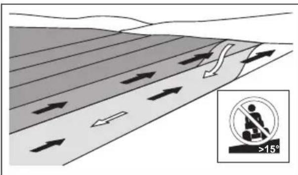
This product is only used to cut grass in private gardens and on private garden slopes with not more than 15^ slope. It is not to be used in public parks, sports grounds, in farming or in forestry. Only use the product with accessories that are approved by the manufacturer.
To use the product differently is incorrect use. It will void your warranty and reject the responsibility for damage to the user of third parties on the part of the manufacturer.
Refer to local directives for the operation of lawn mowers.
Support / Help
If you require assistance or have questions concerning the application, operation, maintenance or parts for your product:
- Visit our website: www.husqvarna.com
• Call Us Toll Free: 1-800-487-5951
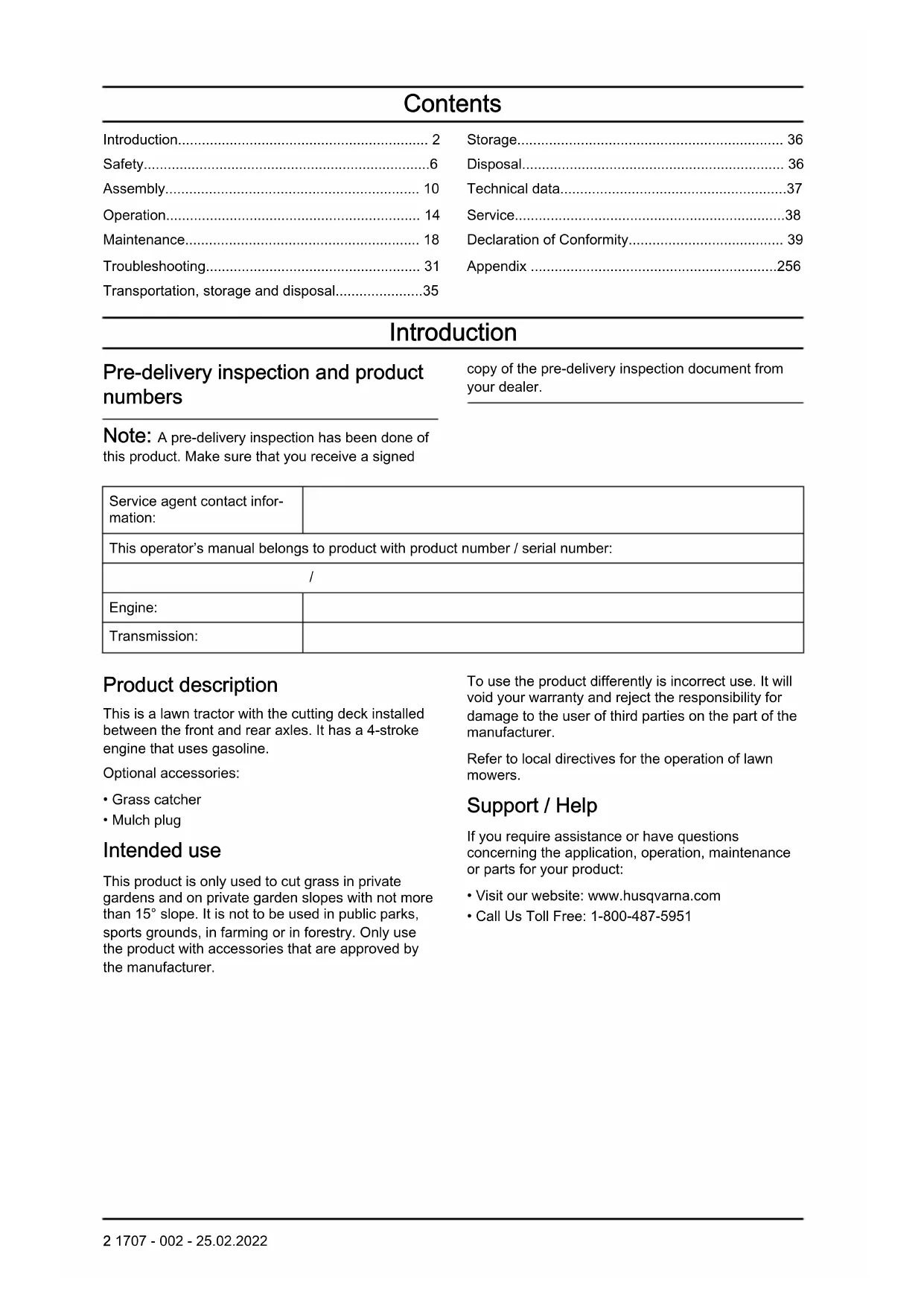
- Light switch
- Throttle control
- Hour meter
- Attachment clutch control
- Ignition switch
- Parking brake lever
- Brake and clutch pedal
- Motion control lever
- Attachment lift lever
- Freewheel lever
Symbols on the product

Warning! Be careful and use the product correctly. This product can
cause serious injury or death to the operator or others.

CAUTION: Incorrect use can result in damage to the product or personal property.

Read the operator's manual carefully and make sure that you understand the instructions before you use this product.

Reverse.

Neutral.

High.

Low.

Start position for cold weather.

Fast.

Slow.

Choke.

Ignition switch.

Engine off.

Engine start.

Engine on.
Brake and clutch pedal.
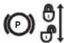
Parking brake.

Parking brake engaged.

Parking brake disengaged.

Cutting height.

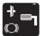
Cutting deck lift.

Reverse operation system (ROS).

Reverse.

Forward.

Lights on.
Fuel.

Oil pressure.

Battery.

Ear protection recommended.

The blades are disengaged.

The blades are engaged.

Risk of carbon monoxide poisoning.

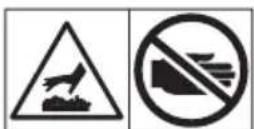
Beware of thrown objects.

Keep bystanders away.

The fire symbol shows a risk, which, if not obeyed, can cause death, serious injury and/or damage.

Sound power level.

The product agrees with the applicable EC directives.

This product conforms to the applicable UK regulations.
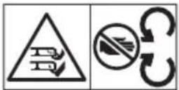
Keep hands and feet away from this area.
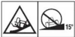
Do not operate the product on slopes that are more than 15°.
Hot surfaces. Do not touch.
The deflector shield on the cutting deck must be installed when you operate the product.
The grass catcher must be installed when you operate the product.
Hand entanglement.
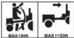
Drawbar load.


Freewheel (automatic models only).
Hour meter
The hour meter shows how many hours the engine has been in operation. Refer to Product overview on page 3 for the position of the hour meter.
Each 50 hours an oil level symbol will show for 2 hours. Refer to Lubrication schedule on page 20.
To manually reset the hour meter, turn the ignition key to the on position and then to the "STOP" position 5 times.
Note: The hour meter only stops when the ignition key is in the "STOP" position. Make sure that the ignition key stays in the "STOP" position when the engine has stopped.
Product liability
As referred to in the product liability laws, we are not liable for damages that our product causes if:
• the product is incorrectly repaired.
• the product is repaired with parts that are not from the manufacturer or not approved by the manufacturer.
• the product has an accessory that is not from the manufacturer or not approved by the manufacturer.
• the product is not repaired at an approved service center or by an approved authority.

WARNING: Tampering with the engine voids the EU type-approval of this product.
Safety
Safety definitions
Warnings, cautions and notes are used to point out specially important parts of the manual.

WARNING: Used if there is a risk of injury or death for the operator or bystanders if the instructions in the manual are not obeyed.

CAUTION: Used if there is a risk of damage to the product, other materials or the adjacent area if the instructions in the manual are not obeyed.
Note: Used to give more information that is necessary in a given situation.
Safe Operation Practices for Ride-On Mowers

WARNING: This product is capable of amputating hands and feet and throwing objects. Failure to observe the following safety instructions could result in serious injury or death.

WARNING: In order to prevent accidental starting when setting up, transporting, adjusting pr making repairs, always disconnect spark plug wire and place wire where it cannot contact spark plug.

WARNING: Do not coast down a hill in neutral, you may lose control of the tractor.

WARNING: Tow only attachments that are recommended by and comply with specifications of the manufacturer of your tractor. Use common sense when towing. Operate only at the lowest possible speed when on a slope. Too heavy of a load, while on a slope, is dangerous. Tires can lose traction with the ground and cause you to lose control of your tractor.

WARNING: Engine exhaust, some of its constituents, and certain vehicle components contain or emit chemicals known to the State of California to cause cancer and birth defects or other reproductive harm.
I. CHILDREN

WARNING: CHILDREN CAN BE INJURED BY THIS EQUIPMENT. The American Academy of Pediatrics recommends that children be a minimum of 12 years of age before operating a pedestrian controlled lawn mower and minimum of 16 years of age before operating a riding lawn mower.

WARNING: CHILDREN CAN BE SERIOUSLY INJURED OR KILLED BY THIS EQUIPMENT. Carefully read and follow all the safety instructions below.
Tragic accidents can occur if the operator os not alert to the presence of children. Children are often attracted t othe machine and the mowing activity. Never assume that children will remain where you last saw them.
- Keep children out of the mowing area and in the watchful care of a responsible adult other than the operator.
- Be alert and turn machine off if a children enters the area.
- Before and while backing, look behind and down for small children.
- Never carry children, even with the blades shut off. They may fall off and be seriously injured or interfere with safe machine operation. Children who have been given rides in the past may suddenly appear in the mowing area for another ride and be run over or backed over by the machine.
- Never allow children to operate the machine.
- Use extreme caution when approaching blind corners, shrubs, trees, or other objects that may block your view of a child.
II. GENERAL OPERATION
- Read, understand, and follow all instructions on the machine and in the manual before starting.
- Do not put hands or feet near rotating parts or under the machine. Keep clear of the discharge opening at all times.
- Only allow responsible adults, who are familiar with the instructions, to operate the machine.
- Clear the area of objects such as rocks, toys, wire, etc., which could be picked up and thrown by the blades.
- Ensure the area is clear bystanders before operating. Stop machine if anyone enters the area.
- Never carry passengers.
- Do not mow in reverse unless absolutely necessary. Always look down and behind before and while backing.
- Never direct discharged material toward anyone. Avoid discharging material against a wall or obstruction. Material may ricochet back toward operator. Stop the blades when crossing gravel surfaces.
- Do not operate machine without the entire grass catcher, discharge chute, or other safety devices in place and working.
- Slow down before turning.
- Never leave a running machine unattended. Always turn off blades, set parking blade, and stop engine before dismounting.
- Disengage blades when not mowing. Shut off engine and wait for all parts to come to complete stop before cleaning the machine, removing the grass catcher, or unclogging the discharge chute.
- Operate machine only in daylight or good artificial light.
- Do not operate the machine while under the influence of alcohol or drugs.
- Watch for traffic when operating near or crossing roadways.
- Use extreme caution when loading or unloading the machine into a trailer or truck.
• Always wear eye protection when operating machine.
- Use ear protectors to avoid damage to hearing.
- Data indicates that operators, age 60 years and above, are involved in a large percentage of riding mower-related injuries. These operators should evaluate their ability to operate the riding mower safely enough to protect themselves and others from serious injury.
- Follow the manufacturer's recommendation for wheel weights or counterweights.
- Keep machine free of grass, leaves or other debris build-up which can touch hot exhaust/ engine parts and burn. Do not allow the mower deck to plow leaves or other debris which can cause build-up to occur. Clean any oil or fuel spillage before operating or storing the machine. Allow machine to cool before storage.
Safety instructions for operation
Personal protective equipment

WARNING: Read the warning instructions that follow before you use the product.
- Use approved personal protective equipment when you use the product. Personal protective equipment cannot fully prevent injury but it decreases the degree of injury if an accident does occur. Let your dealer help you select the right equipment.
• Always wear approved hearing protection. Long term exposure to noise can result in permanent hearing impairment.
• Always wear protective shoes or protective boots. Steel toes are recommended. Do not use the product barefoot.
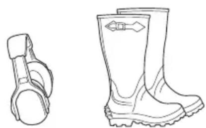
natural_image
Line drawings of two different boots, one with a side view and the other with a handle (no text or symbols)- Wear gloves when necessary, for example when you attach, examine or clean the cutting equipment.
- Do not wear loose-fitting clothing, jewelry or other items that can get caught in moving parts.
- Keep first aid equipment and fire extinguisher close at hand.
Safety devices on the product

WARNING: Read the warning instructions that follow before you use the product.
- Do not use a product with defective safety devices. Do a check of the safety devices regularly. If the safety devices are defective, speak to your Husqvarna service agent.
- Do not make modifications on safety devices. Do not use the product if protective plates, protective covers, safety switches or other protective devices are not attached or are defective.
To do a check of the operator presence control (OPC)

WARNING: Do not operate the product if the operator presence control (OPC) is defective. If the OPC is
defective, repair it immediately. Speak to an approved service agent.
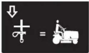
- Make sure that the engine cannot start unless the brake pedal is pushed down fully and the cutting deck is disengaged.
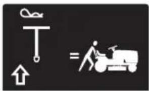
- Make sure that the engine stops when the operator goes away from the seat when the parking brake is disengaged.
- Make sure that the engine stops when the operator goes away from the seat when the cutting deck is engaged.
- Make sure that the clutch control for the cutting deck cannot operate when the operator is away from the seat.
To do a check of the reverse operation system (ROS)
If the reverse operation system does not operate correctly, repair the product immediately. Speak to an approved service agent.
- Start the product. Refer to To start the product on page 14.
- Engage the cutting deck. Refer to To engage and disengage the cutting deck on page 17.
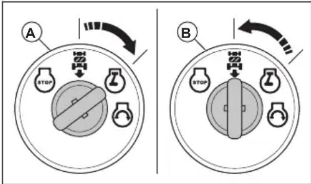
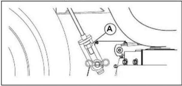
- Make sure that the engine stops when you try to reverse with the ignition key is in the on position (A).
-
Start the product and engage the cutting deck again.
-
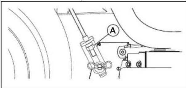
Turn the ignition switch to the ROS on position (B).
-
Make sure that the engine does not stop when you reverse with the ignition key in the ROS on position.
To do a check of the brake

WARNING: Brake maintenance is necessary if the product uses more than 5 ft (1.5 m) to stop at the highest speed in the highest gear on a level, dry surface.
-
Park the product on a level, dry concrete or paved surface. Push the brake pedal down fully and engage the parking brake.
-
Set the freewheel control to the "transmission disengaged" position to disengage the transmission.
- The rear wheels must lock and skid when you try to manually push the product forward. If the rear wheels rotate, then brake maintenance is necessary.
- Speak to an approved service center.
Parking brake

WARNING: If the parking brake does not work, the product can start to move and cause injury or damage. Make sure that the parking brake is regularly examined and adjusted.
Refer to To do a check of the brake on page 8.
Muffler
The muffler keeps the noise levels to a minimum and sends the exhaust fumes away from the operator.
Do not use the product if the muffler is missing or defective. A defective muffler increases the noise level and the risk of fire.

WARNING: The muffler becomes very hot during and after use and when the engine operates at idle speed. Be careful near flammable materials and/or fumes to prevent fire.
To do a check of the muffler
- Examine the muffler regularly to make sure that it is attached correctly and not damaged.
To cut grass on slopes

WARNING: Read the warning instructions that follow before you use the product.
- To cut grass on slopes increases the risk that you can not control the product and that it overturns. This can cause injury or death. It is necessary to cut the grass carefully on all slopes. If you cannot reverse up a slope or if you do not feel safe, do not cut it.
- Remove stones, branches and other obstacles.
- Cut up and down the slope, not from side to side.
- Do not move down a slope with the cutting deck lifted.
- Do not operate the product on ground that slopes more than 15^ .
- Do not start or stop on a slope.
- Move smoothly and slowly on slopes.
- Do not make sudden changes in speed or direction.
- Do not turn more than necessary. Turn slowly and gradually when you move down a slope. Move at low speed. Turn the wheel carefully.
- Look out for and do not move across furrows, holes and bumps. There is a higher risk that the product overturns on ground that is not flat. Long grass can hide obstacles.
- Do not cut grass near edges, ditches or banks. The product can suddenly overturn if a wheel moves across the edge of a steep slope or a ditch, or if an edge gives way.
- Do not mow wet grass. It is slippery, and tires can lose their grip so that the product skids.
- Do not put your foot on the ground to try to make the product more stable.
- Move very carefully if an accessory or other object is attached that can make the product less stable.
Fuel safety

WARNING: Read the warning instructions that follow before you use the product.
- Fuel is flammable and the fumes are explosive. Be careful with fuel to prevent injury, fire and explosion.
- Do not breathe in the fuel fumes. The fuel fumes are poisonous and can cause injury. Make sure that the airflow is sufficient.
- Do not remove the fuel tank cap or fill the fuel tank when the engine is on.
- Let the engine become cool before you refuel.
- Do not fill fuel in an indoor area. Not sufficient airflow can cause injury or death because of asphyxiation or carbon monoxide.
- Do not smoke near the fuel or the engine.
- Do not put hot objects near the fuel or the engine.
- Do not fill fuel near sparks or flames.
-
Before you refuel, open the fuel tank cap slowly and release the pressure carefully.
-
Fuel on your skin can cause injury. If you get fuel on your skin, use soap and water to remove the fuel.
- If you spill fuel on your clothing, change clothing immediately.
- Do not fill the fuel tank fully. Heat causes the fuel to expand. Keep a space at the top of the fuel tank.
- Tighten the fuel tank cap fully. If the fuel tank cap is not tightened, there is a risk of fire.
- Before you start the product, move the product to a minimum of 3 m/10 ft from where you refueled.
- Do not start the product if there is fuel or engine oil on the product. Remove the unwanted fuel and engine oil and let the product dry before you start the engine.
- Examine the engine for leaks regularly. If there are leaks in the fuel system, do not start the engine until the leaks are repaired.
- Do not use your fingers to examine the engine for leaks.
- Keep fuel in approved containers only.
- When the product and fuel is in storage, make sure that fuel and fuel fumes cannot cause damage.
- Drain the fuel in an approved container outdoors and away from sparks and flames.
Battery safety

WARNING: A damaged battery can cause an explosion and cause injury. If the battery has a deformation or is damaged, speak to an approved Husqvarna service agent.

WARNING: Read the warning instructions that follow before you use the product.
- Use protective glasses when you are near batteries.
- Do not wear watches, jewelry or other metal objects near the battery.
- Keep the battery out of reach for children.
- Charge the battery in a space with good airflow.
- Keep flammable materials at a minimum clearance of 1 m when you charge the battery.
- Discard replaced batteries. See Disposal on page 36.
• Explosive gases can come from the battery. Do not smoke near the battery. Keep the battery away from open flames and sparks.
Transport safety
- Use an approved transport vehicle for transportation of the product.
- A markets national or local regulations can set limit to the transportation of the product.
- The operator of the transport vehicle is responsible to attach the product safely during transport. Refer to Transportation on page 35.
Safety instructions for maintenance

WARNING: The product is heavy and can cause injury or damage to property or the adjacent area. Do not do maintenance on the engine or the cutting deck without these conditions:
- The engine is off.
- The product is parked on a level surface.
- The parking brake is applied.
• The ignition key is removed.
• The cutting deck is disengaged. - The ignition cables are removed from the plugs.

WARNING: The exhaust fumes from the engine contain carbon monoxide, an odorless, poisonous and very dangerous gas. Do not run the product in closed spaces or spaces with not sufficient air flow.

WARNING: Read the warning instructions that follow before you do maintenance on the product.
- For best performance and safety, do maintenance on the product regularly as given in
the maintenance schedule. Refer to Maintenance schedule on page 19.
- Electrical shocks can cause injuries. Do not touch the cables when the engine is on. Do not do a function test on the ignition system with your fingers.
- Do not start the engine if the protective covers are removed. There is a high risk of injury caused by moving or hot parts.
- Let the product become cool before you do maintenance near the engine.
- The blades are sharp and can cause cuts. Wind protection around the blades or use protective gloves when you do work on the blades.
- Always put the cutting deck in servicing position to clean it. Do not park the product near the edge of a ditch or slope to get access to the cutting deck.

CAUTION: Read the caution instructions that follow before you use the product.
- Do not turn over the engine if the spark plug or ignition cable is removed.
- Make sure that all nuts and bolts are tightened correctly and that the equipment is in good condition.
- Do not change the adjustment of governors. If the engine speed is too high, the product components can become damaged.
- The product is approved only with the equipment supplied or recommended by the manufacturer.
Assembly
Introduction

WARNING: Read and understand the safety chapter before you assemble the product.
To remove the product from the carton
- Remove loose parts included with the product.
- Remove the end panels.
- Remove the side panels and put them on a flat surface.
- Remove all package materials.
- Remove the product from the carton and make sure no loose parts are left in the carton.
Assembly tools
- 1/2" wrench
-
7/16" wrenches (2 pieces)
-
Tire pressure gauge
- Knife
• Pliers - Socket wrench set (optional)
Loose parts that need assembly
The product is not fully assembled. The parts that follow are loose when the product is purchased.

Key, 2 pcs
Slope sheet, 1 pcs
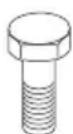
Hex bolt, 2 pcs
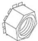
Nuts, 2 pcs
Hood scoop, 1 pcs

Oil drain extension, 1 pcs

Steering wheel, 1 pcs
Center cover for steering wheel, 1 pcs
Steering shaft cover, 1 pcs

Hex bolt for the steering wheel, 1 pcs
Steering wheel adapter, 1 pcs

Steering shaft extension, 1 pcs

Flat washer for steering wheel, 1 pcs

Lock washer for steering wheel, 1 pcs

Seat, 1 pcs

Hex bolt for the seat, 2 pcs

Flat washer for seat, 2 pcs
To install the steering wheel
- Install the steering shaft extension (A) on the steering shaft (B).
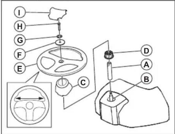
- Install the shaft cover (C). Make sure that the guide tabs in the shaft cover are in the correct positions.
- Remove the steering wheel adapter (D) from the steering wheel (E).
- Put the steering wheel adapter on the steering shaft extension.
- Put the steering wheel on the steering shaft extension.
- Make sure that the front wheels and the steering wheel are aligned forward.
- Install the large flat washer (F), the lock washer (G), and the bolt (H). Tighten the bolt fully.
- Attach the center cover (I) to the steering wheel. The center cover is attached with snap locks.
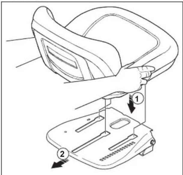
To install the seat
- Remove, but do not discard, the hardware which attaches the seat to the cardboard package.
- Remove and discard the cardboard package.
Note: Do not remove the tape from the adjustment handle until the seat is correctly attached to the product.
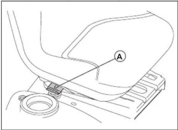
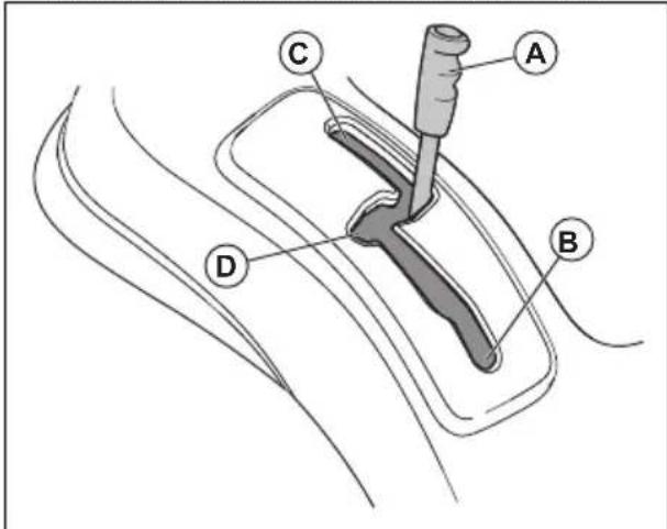
- Connect the wire connector to the safety switch (A) on the seat.
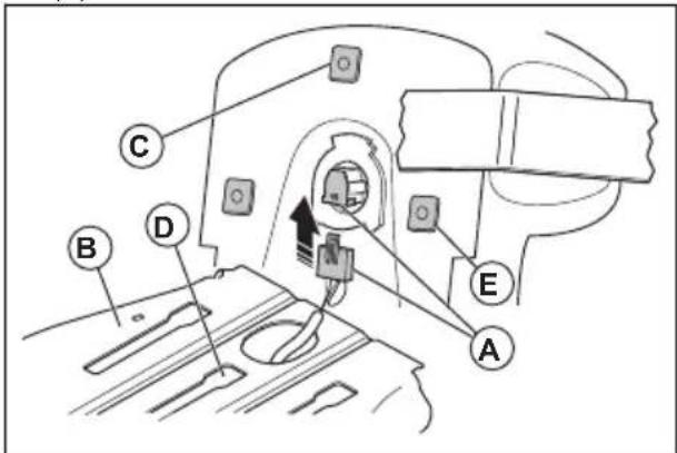
-
Put the seat on the seat pan (B) and put the middle plastic piece (C) into the middle slot assembly hole (D).
-
Push the seat rearward until the 2 front plastic pieces (E) are aligned with the front slot assembly holes. Push down the seat to engage the plastic pieces in the slots. Push the seat rearward.
- Fold the seat forward and install the 2 bolts (F) and the 2 washers (G).
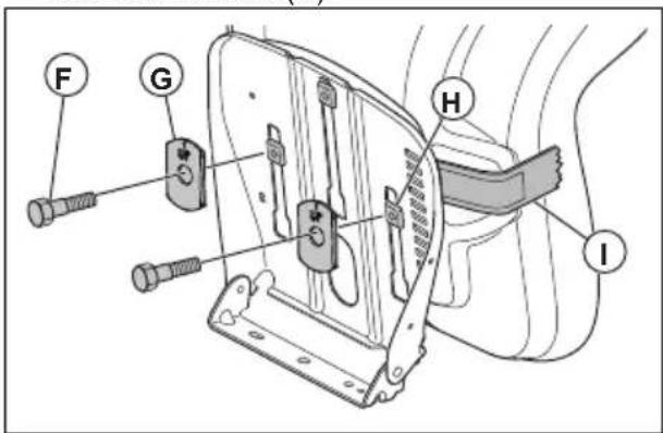
Note: Make sure that the 2 front plastic pieces (H) are fully engaged in the seat pan.
Note: Make sure that the arrows on the 2 washers point up.
-
Remove the tape from the adjustment lever (I) and discard the tape.
-
Do a check of the operator presence control. Refer to To do a check of the operator presence control (OPC) on page 7.

WARNING: Do no operate the product if the operator presence control is defective.
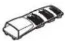
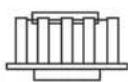
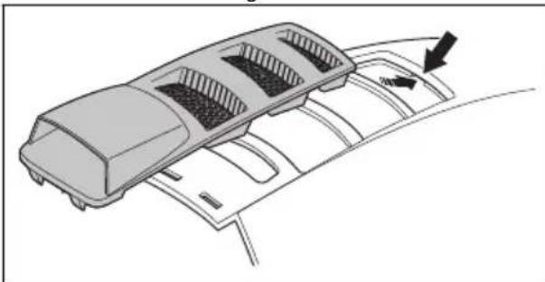
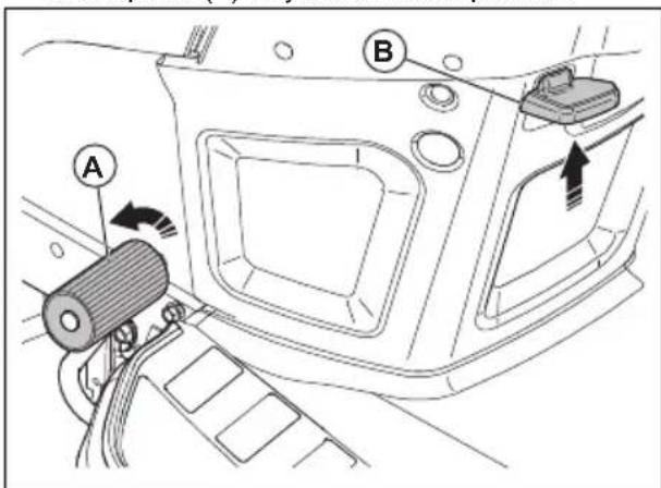
To install the engine cover piece
- Align the front tab on the engine cover piece with the cut-out in the engine cover.
natural_image
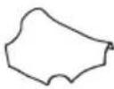
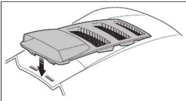
Diagram of a car air vent system with airflow direction indicated by arrows (no text or labels)- Align the rear tabs on the engine cover piece with the cut-outs in the engine cover.
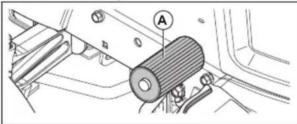
natural_image
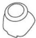
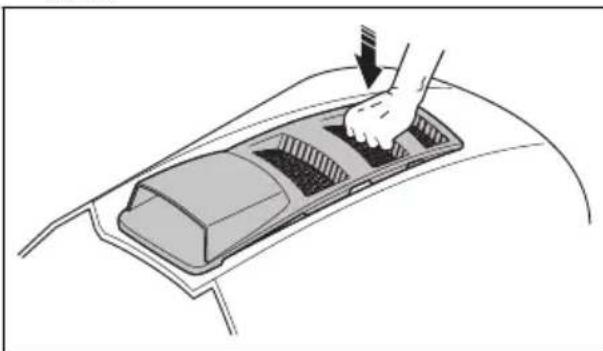
Diagram of a car air intake tray with directional arrows indicating airflow or movement (no text or symbols)- Push down the engine cover piece on the engine cover.
natural_image
Diagram of a hand pressing down on a car intake tray (no text or symbols)To adjust the seat
-
Sit in the seat.
-
Lift up the seat adjustment lever (A).
-
Move the seat until it is in a position where you can push the brake and clutch pedals down.
-
Release the seat adjustment lever (A) to lock the seat in position.
To connect the battery

WARNING: Risk of electrical shock and burn injuries. Do not use metal wristbands or other metal accessories. Metal items that touch the battery terminals can cause burn injuries, electrical shock, and short circuit of the battery.
Note: If it is after the year and month that is written on the battery label, charge the battery. Charge the battery for a minimum of 1 hour at 6–10 A.
-
Find the battery location below the seat or the engine cover.
-
Lift the seat pan or the engine cover to the raised position.
-
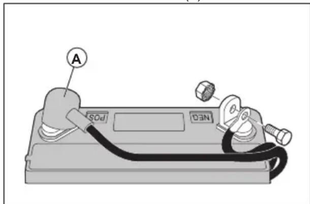
Remove the 2 terminal caps (A) and discard them.
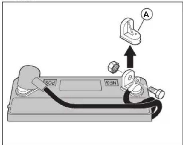
- Connect the red battery cable to the positive (+) terminal and tighten the bolt and nut as shown. Move the terminal cover on the terminal.

WARNING: Risk of sparks. The red battery cable must be connected to the positive terminal before the black battery cable is connected to the negative terminal. This is to prevent sparks and accidental grounding.
- Connect the black cable to the negative (-) terminal and tighten the bolt and nut fully.
- Apply petroleum jelly on the battery cables to prevent corrosion.
- Lower the seat pan or the engine cover.
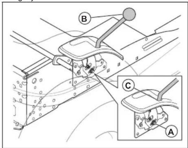
To move the product off the skid
- Lift the cutting deck to its highest position. Use the lift lever.
- Push the clutch/brake pedal down to release the parking brake.
- Put the freewheel control in the "Transmission disengaged" position, refer to Transportation, storage and disposal on page 35.
- Push the product forward off the skid.
- Remove the strap that holds the deflector protection up against the product.
To do a check after the assembly
- Make sure that all assembly instructions are completed.
• Make sure that no remaining parts are in the package.
• Make sure that the battery is prepared and charged correctly.
• Make sure that the bolts for the seat are tightened and that the seat is adjusted correctly. - Make sure that the tires are correctly inflated.
- For best cutting results, make sure that the cutting deck is balanced side to side and front to rear. Make sure that the tires are correctly inflated for a balanced cutting deck.
- Examine the cutting deck and the drive belts. Make sure that the drive belts are installed correctly around the pulleys and inner part of all belt keepers.
- Examine the electrical wires. Make sure that all wires and connections are safe.
- Make sure that the freewheel control is in the “Transmission engaged” position. Refer to Transportation on page 35.
• Make sure that the engine oil is at the correct level. - Make sure that the tank is filled with the correct type of fuel.
• Make sure that you know the location and function of all controls. - Make sure that the brake system is in safe to operate condition.
- Make sure that the Operator Presence Control (OPC) and the Reverse Operation System (ROS) operate correctly. Refer to To do a check of the operator presence control (OPC) on page 7 and To do a check of the reverse operation system (ROS) on page 8.
- Remove the air from the transmission before first use. Refer to To remove the air from the transmission on page 30.
Operation
Introduction

WARNING: Read and understand the safety chapter before you use the product.
To fill fuel

WARNING: Gasoline is very flammable. Be careful and refuel outdoors. Refer to Fuel safety on page 9

CAUTION: Always use correct fuel type. Incorrect fuel type causes damage to the product.
- Use gasoline of the correct type. Refer to Technical data on page 37. For more information about the fuel, refer to the engine manual supplied by the engine manufacturer.
- Do a check of the fuel level before each use and refuel if necessary.
- Do not fully fill the fuel tank. Keep a space of a minimum 1 in.
To start the product
To do before you start the product

WARNING: Before you operate the product, carefully read and understand the safety instructions and the operation instructions.
- Do a check of the engine oil level. Refer to To do a check of the engine oil level on page 28.
- Fill the fuel tank with fuel. Refer to To fill fuel on page 14.
- Disengage the freewheel mode. Refer to To put the product in freewheel mode on page 18.
- Sit in the seat in operation position.
- Engage the parking brake. Refer to To engage and disengage the parking brake on page 16.
- Make sure that the cutting deck is disengaged. Refer to To engage and disengage the cutting deck on page 17.
To start a warm engine
- Sit on the seat.
- Make sure that the cutting deck is disengaged. Refer to To engage and disengage the cutting deck on page 17.
- Put the cutting deck in transport position. Refer to To set the cutting deck in transport position or mow position on page 15
- Put the motion control lever in the neutral position.
- Move the throttle control to the fast position.
- Push down on the brake pedal fully and hold it down.
- Put the ignition key into the ignition.
- Turn the ignition key to the "START" position and release the ignition key when the engine starts.

CAUTION: Do not operate the starter continuously for more than 15 seconds for each minute.
- If the temperature is low, let the engine become warm before you start to cut grass.
To start a cold engine
-
Sit on the seat.
-
Make sure that the cutting deck is disengaged. Refer to To engage and disengage the cutting deck on page 17.
-
Put the cutting deck in transport position. Refer to To set the cutting deck in transport position or mow position on page 15
-
Put the motion control lever in the neutral position.
-
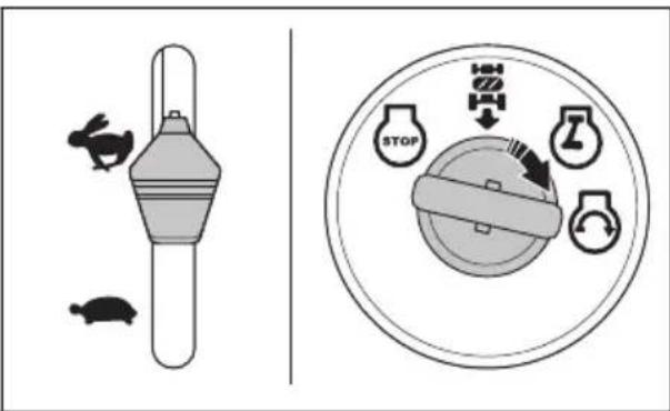
Move the throttle control to the choke position.
-
Push down on the brake pedal fully and hold it down.
-
Put the ignition key into the ignition.
-
Turn the ignition key to the "START" position and release the ignition key when the engine starts.

CAUTION: Do not operate the starter continuously for more than 15 seconds for each minute.
- When the engine starts, move the throttle control to the fast position (D) to warm up the engine. If the temperature is low, some minutes is necessary for the engine to get warm.

CAUTION: If the ambient temperature is less than 40^ F ( 4^ C), you must let the engine operate 1 minute at idle speed before you operate the product. This is to let the transmission warm up. Make sure that the motion control lever is in the neutral position and that the brake pedal is fully released.
To start the engine when the battery is weak

WARNING: Lead-acid batteries can make explosive gases. Keep sparks, flames and smoking materials away from batteries. Always wear eye protection when around batteries.
If the battery is too weak to start the engine, it must be charged.
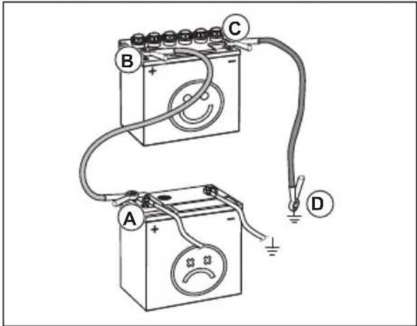
If the jumper cables are used for emergency starting, follow the procedures below:
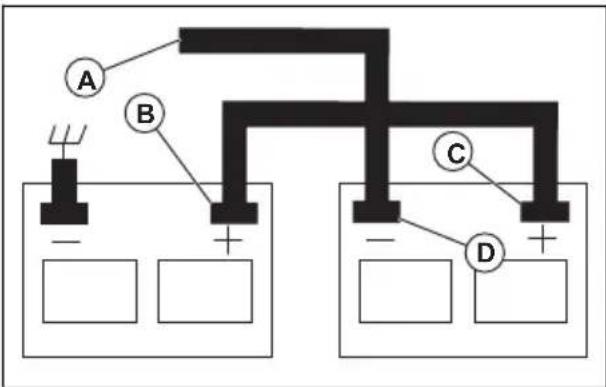
- Connect one end of the RED cable to the POSITIVE (+) terminal of each battery (B-C).

CAUTION: Be careful that a short circuit does not occur against the chassis of the product.
- Connect one end of the BLACK cable to the NEGATIVE (-) terminal (D) of a fully charged battery.
- Connect the other end of the BLACK cable (A) to good chassis ground, away from the fuel tank and battery.
- Remove the BLACK cable from the chassis when the weak battery is fully charged.
- Remove the BLACK cable from the fully charged battery.
- Remove the RED cable from the two batteries.
To remove the jumper cables
Note: Remove the jumper cables in the opposite sequence to how you connect them.
- Remove the BLACK cable from the chassis.
- Remove the BLACK cable from the fully charged battery.
- Remove the RED cable from the 2 batteries.
To set the cutting deck in transport position or mow position
The cutting deck must be in transport position during transportation.
- To set the product in transport position, pull the cutting height lever in the direction of the seat and put it in the highest cutting height position.
- To set the product in mow position, set the correct cutting height. Refer to To set the cutting height on page 15.
To set the cutting height
natural_image
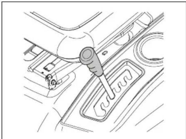
Technical line drawing of a car interior showing a hand tool interacting with a gear shift (no text or symbols)- Pull the lift lever in the direction of the seat and put it in 1 of the notches for the correct cutting height.
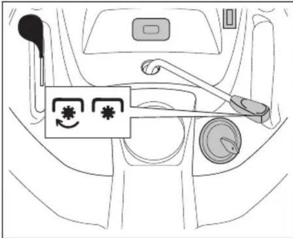
To move forward and rearward
The direction and speed of movement is controlled by the motion control lever.
- Start the engine.
- Disengage the parking brake. Refer to To engage and disengage the parking brake on page 16.
- To start movement, slowly move the motion control lever (A) forward (B) or rearward (C).
- Move the motion control lever more forward or rearward to increase the speed.
- Put the motion control lever in the neutral position (D) when you park and stop the product.
To engage and disengage the parking brake
- To engage the parking brake, push down the brake pedal (A) fully to the lowest position.
- With the brake pedal pushed down, pull up the parking brake lever (B).
- Release the brake pedal.
- Release the parking brake lever.
Note: Make sure that the parking brake holds the product safely.
- To release the parking brake, push down the brake pedal.
To stop the product

WARNING: Always stop the product, engage the parking brake and remove the ignition key before you go away from the product.

CAUTION: The exhaust gas from the warm engine can cause burn damage to the grass. To prevent burn damage to the grass, always stop the engine when you stop the product on grass areas.
- Push down on the brake pedal (A) fully until the product stops fully.
- Put the motion control lever in the neutral position. Refer to To move forward and rearward on page 16.
- Disengage the cutting deck. Refer to To engage and disengage the cutting deck on page 17.
- Put the throttle control in the slow position and let the engine operate at idle speed for some minutes.
- Put the cutting deck in the transport position. Refer to To set the cutting deck in transport position or mow position on page 15.
- Turn the ignition key to the "STOP" position and remove the ignition key from the ignition.
To use the throttle control
The throttle control adjusts the engine speed and the speed of the blades in the cutting deck.
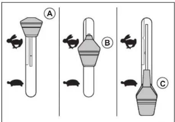
- Put the throttle control in the choke position (A) when you start a cold engine. Refer to To start a cold engine on page 14.
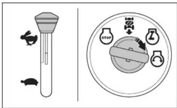
- Put the throttle control in the fast position (B) to operate the engine at full speed. Always have the throttle control in the fast position when you cut grass.
- Put the throttle control in the slow position (C) to operate the engine at idle speed.
To use the headlight
- Push the power switch to position (A) to make the headlight come on.
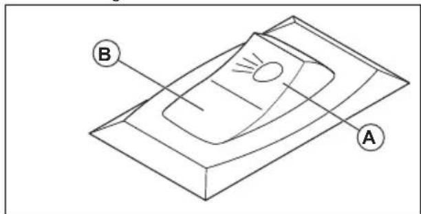
- Push the power switch to position (B) to make the headlight go off.
To engage and disengage the cutting deck

WARNING: Do not operate the cutting deck without a deflector or grass catcher installed to the grass discharge.
The product has an operator presence control (OPC). When you go away from the seat with the engine on and the cutting deck engaged, the engine stops.
Stay fully and in the center of the seat to make sure that the engine operates correctly and does not stop on rough terrain or hills.
-
Set the correct cutting height. Refer to To set the cutting height on page 15.
-
Move the attachment clutch control.
a) Move the attachment clutch control forward to engage the cutting deck.
b) Move the attachment clutch control rearward to disengage the cutting deck.
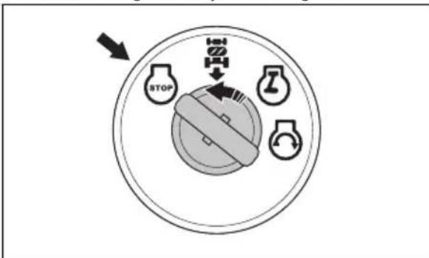
To use the reverse operation system (ROS)
Note: If you try to go rearward with the product when the cutting deck is engaged, the engine stops immediately. Engage the ROS to go rearward with the product when the cutting deck is engaged.

WARNING: Before and while you operate the product rearward, look down and behind the product for the safety of others.
- Put the motion control lever in the neutral position.
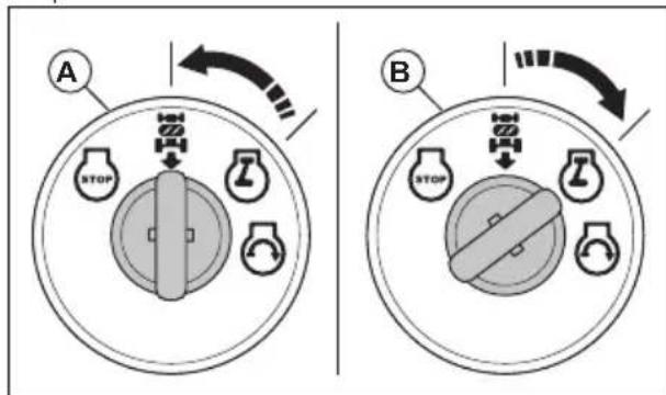
- Turn the ignition key counterclockwise to the ROS "ON" position (A) to engage the ROS.
- Slowly move the motion control lever to the reverse position to start movement.
- Turn the ignition key clockwise to the engine "ON" position (B) to disengage the ROS.
To get a good cutting result
- For best performance, do maintenance on the product regularly as given in the maintenance schedule. Refer to Maintenance schedule on page 19.
- Do not cut a wet lawn. Wet grass can give a bad cutting result.
- Do not use tire chains when you attach the cutting deck to the product.
• Make sure that the cutting deck is level. Refer to To adjust the parallelism of the cutting deck on page 25. - If the grass is high, start with a high cutting height and decrease it gradually.
- Move the product forward at low speed if the grass is high and thick.
- Use full throttle when you cut the grass.
- Cut the grass in an irregular pattern.
- Use the left side of the cutting deck when you cut near trees, bushes or paths. The blade cuts approximately 15 mm in from the side of the cutting deck.
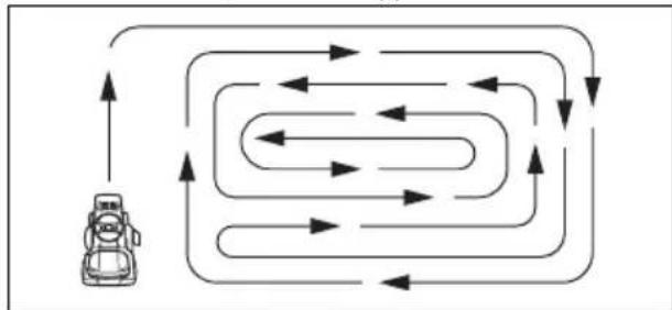
- When you cut large areas, move the product to the right during 1 or 2 turns around the work area. This procedure will keep the grass discharge away from shrubs, fences and driveways. After approximately 2 turns around the work area, cut in the opposite direction.
• To get the best cutting result, cut the grass frequently.
To put the product in freewheel mode
If it is necessary to move or tow the product without aid from the engine, you must put the product in freewheel mode.

WARNING: Do not put the product in freewheel mode on a slope.
- Push in the freewheel control lever (A) to put the product in freewheel mode.
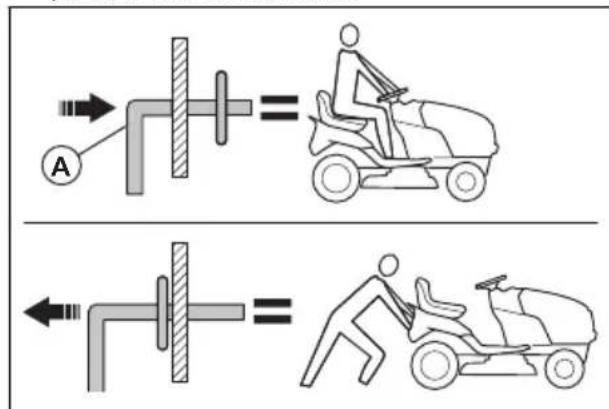
- Pull out the freewheel control lever to operate the product with the engine.
To install the mulch plug (accessory)
The product can be used with a mulch plug.
- Put the cutting deck in the transport position. Refer to To set the cutting deck in transport position or mow position on page 15.
- Remove the grass catcher or the rear discharge deflector (accessory) if it is installed.
- Put the mulch plug through the back plate and into the chute adaptor for the cutting deck.
- Connect the 2 straps to the holes on the support arms for the grass catcher.
- Install the grass catcher or the rear discharge deflector.
- Remove the mulch plug in the opposite sequence.
Maintenance
Introduction

WARNING: Read and understand the safety chapter before you do maintenance on the product.
Maintenance schedule
| Maintenance schedule Before | each use | At intervals of 8 hours | At intervals of 25 hours | At intervals of 50 hours | At intervals of 100 hours | Each season | Before storage | |
| Product Do a check of the brake function. | X | X | ||||||
| Do a check of tire pressure. | X | X | ||||||
| Do a check of the operator presence control (OPC). | X | |||||||
| Do a check of the reverse operation system (ROS). | X | |||||||
| Do a check for loose fasteners. | XXX | |||||||
| Examine the blades for wear and damage. | X^2 | |||||||
| Lubricate the product. Refer to Lubrication schedule on page 20. | X | X | ||||||
| Do a check of the battery level. | X | |||||||
| Clean the battery and the terminals. | X | X | ||||||
| Clean pieces off the steering plate. Refer to To clean the product on page 21. | X | |||||||
| Do a check of the trans-axle cooling fan. | X | |||||||
| Make sure that the cutting deck is level. | X | |||||||
| Do a check of the V-belts. | X | |||||||
| Engine Do a check of the engine oil level. | X | X | ||||||
| Change the engine oil (models with oil filter). | X^1 | X | ||||||
| Change the engine oil (models without oil filter). | X^1 | X | ||||||
| Clean the air filter. X | 3 | |||||||
| Clean the air screen. X | 3 | |||||||
| Do an inspection of the muffler and the spark arrester. | X | |||||||
| Replace the oil filter (if it is equipped). | X^1 | X | ||||||
| Clean the engine cooling fins. | X^3 | |||||||
| Replace the spark plug. X X | ||||||||
| Replace the paper cartridge of the air filter. | X^3 | |||||||
| Replace the fuel filter X | ||||||||
| Do a check of the muffler. Refer to To do a check of the muffler on page 8. | X | |||||||
Lubrication schedule

CAUTION: Do not lubricate the pivot points that have special nylon bearings. Tacky lubricants can attach dirt. The dirt decreases the life of the special nylon bearings. If it is necessary to lubricate the nylon bearings, use only a small quantity of dry type lubricant.
A. General lubrication. Lubricate the spindle grease connection, front wheel bearing, gear teeth of the steering part.
B. Engine lubrication. Refer to To lubricate the engine on page 28 in the Maintenance section.
Tractor
To clean the product
Do not use a garden hose or a pressure washer to clean the surface except for the washout port. Keep water out of the engine and transmission. Water in the engine or transmission can decrease the life of the product. Use compressed air or a leaf blower to remove grass, leaves and litter.
- Clean all unwanted material from the engine, battery, seat and other parts of the product.
- Clean contamination from the steering plate. Contamination limits the movement of the clutch/brake pedal shaft, causes the belt to loosen and decreases forward movement.

CAUTION: Avoid all pinch points and movable parts.
- Keep the surfaces and wheels free of all gasoline, oil, and so on.
- Use automotive type wax to prevent damage to the surfaces.
To use the deck washout port
The cutting deck has a deck washout port that is a part of the cleaning system for the cutting deck.

WARNING: Do not use the product with a broken or missing deck washout port. There is a risk of thrown objects. Replace a broken or missing deck washout port immediately.
Note: For the models with guards, the washout port is installed on the left side guard in front of the rear tire.
- Park the product in a clear area on your lawn that is near a water source with a garden hose.

CAUTION: Do not point the discharge chute of the product in the direction of buildings or vehicles.
- Make sure that the cutting deck is disengaged. Refer to To engage and disengage the cutting deck on page 17.
- Turn the ignition key to the STOP position to stop the engine.
- Engage the parking brake.
- Remove the grass catcher chute or the mulch plug if it is installed.
- Put the nozzle adapter onto the end of your garden hose (A). Make sure that the garden hose is fully connected to the nozzle adapter.
- Pull back on the lock collar of the nozzle adapter and push the nozzle adapter onto the deck washout port (B).
- Carefully pull on the garden hose to make sure that it is fully connected.
- Release the lock collar to lock the adapter on the deck washout port.
- Start the water supply.
- Sit in the seat and start the engine.

CAUTION: Examine the area again to make sure that the area is clear.
- Move the throttle control to the fast position. Refer to To use the throttle control on page 16.
- Engage the cutting deck and let it operate until the cutting deck is clean. Refer to To engage and disengage the cutting deck on page 17.
- Disengage the cutting deck. Refer to To engage and disengage the cutting deck on page 17.
-
Turn the ignition key to the STOP position to stop the engine.
-
Stop the water supply.
- Pull back the lock collar of the nozzle adapter and disconnect the nozzle adapter from the deck washout port.
- Move the product to a dry area.
- Engage the cutting deck and let it operate until the cutting deck is dry.
To adjust the throttle control cable
The throttle control is set at the factory and adjustment should not be necessary. If an adjustment is necessary, see the Engine manual.
To examine the interlocks and the relays
Note: Loose or damaged wires can make your product run unsatisfactorily, stop running or prevent it from starting.
- Examine the wires.
To replace the headlight bulb
- Open the engine cover.
- Turn the bulb holder slightly counterclockwise and pull it out of the holder behind the grill.
- Replace the bulb in the bulb holder.
- Push the bulb holder into the holder behind the grill.
- Turn the bulb holder slightly clockwise to install it.
- Close the engine cover.
To do a check of the tires
Note: To seal the tire holes and prevent flat tires because of slow leaks, purchase sealant from your local parts dealer. Tire sealant also prevents tire dry rot and corrosion.
- Make sure the air pressure in all tires is correct (See the sides of tires for correct PSI).
- Keep the tires free of gasoline, oil or insect control chemicals that can cause damage to the rubber.
- Keep the tires away from stumps, stones, rut pits, sharp objects and other dangerous objects that may cause tire damage.
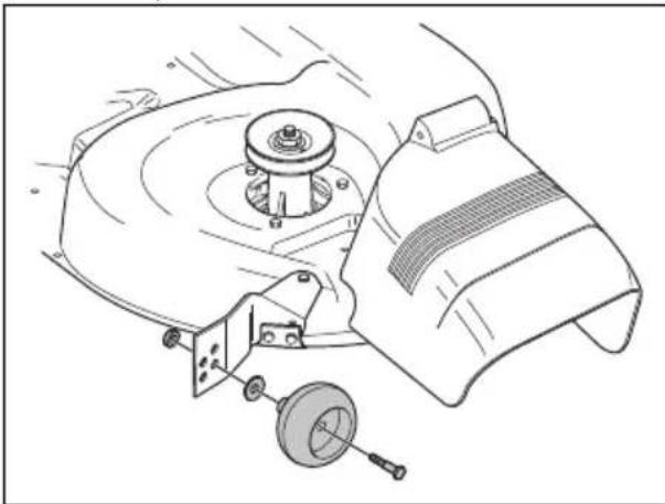
To repair the tires
- Lift the front axle and support it safely.

CAUTION: Lift and support one axle at a time.
- Remove the dust cover (A), the E-clip (B), the washer (C) and the square key (D).
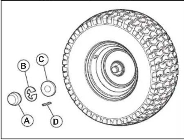
Note: There are square keys on the rear wheels only.
- Remove the wheel from the axle.
- Remove the tire from the wheel.
- Repair the tire.
Note: Use tire sealant to seal holes in the tire. Tire sealant also prevents tire dry rot and corrosion.
- Install the tire on the wheel.
- Install the wheel, the washer, the square key, and the E-clip on the axle. Make sure that the E-clip is installed correctly in the groove on the axle.
- Install the dust cover.
To examine the V-belts
The belts are not adjustable.
- Examine the V-belts for deterioration and wear after each interval of 100 hours of operation.
- Replace the V-belts if they start to move because they are too worn.
To do maintenance on the transaxle cooling fan

CAUTION: Do not clean the fan or the transmission while the engine is on or while the transmission is hot.

CAUTION: Do not use a high-pressure washer or a steam cleaner. Water can go into bearings and electrical connections and cause corrosion which causes damage to the product.
To keep the transmission cool, keep the transmission fan and cooling fins clean.
- Before you clean with water, clean with a brush. Remove grass cuttings and dirt on and around the transaxle fan and cooling fins.
- Examine the cooling fan to make sure the fan blades are clean and not damaged.
To examine the transaxle pump fluid
• Make sure that the transaxle pump fluid does not leak.
- Speak to the nearest approved service center or department if the transaxle pump fluid leaks.
To adjust the front wheel toe-in and camber
The front wheel toe-in and camber is correctly set at the factory. The front wheel toe-in and camber are not adjustable.
- Speak to an approved service center if the factory-set front wheel toe-in or camber is damaged.
To replace the fuse
This product has an automotive-type fuse. The fuse holder is located behind the dashboard.
- Hold the fuse holder and pull the blown fuse out.
- Put a new fuse in the fuse holder.
To remove and install the engine cover and the grill assembly
- Lift the engine cover.
- Disconnect the headlight wire connector (A).
- Stay in front of the tractor. Hold the engine cover on its sides. Tilt the engine cover in the direction of the engine and lift it to remove it from the product.
- Install in the opposite sequence.
To replace the drive belt
- Park the product on a level surface and engage the parking brake. Refer to To stop the product on page 16.
-
Remove the cutting deck. Refer to To remove and install the cutting deck on page 25.
-
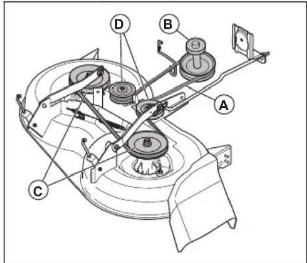
Remove the drive belt from the pulley (A) and the clutch pulley (B).
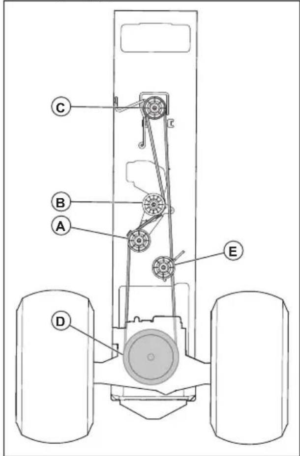
- Remove the drive belt from the engine pulley (C) on the engine shaft.
- Remove the drive belt from the rear axle pulley (D) and the belt tension pulley (E).
- Remove the drive belt from the product.
- Install a new drive belt in the opposite sequence.
To adjust the motion control lever
The motion control lever is correctly adjusted from factory. Only adjust the motion control lever if the product moves when the motion control lever is in the neutral position.
- Loosen the adjustment bolt (A) and tighten it lightly.
-
Start the engine.
-
Move the motion control lever (B) forward or rearward until the product does not move. Hold the motion control lever in this position and stop the engine.
-
Loosen the adjustment bolt.
-
Move the motion control lever to the neutral position (C).
-
Tighten the adjustment bolt fully.
Battery
To clean the battery and the terminals
Corrosion and dirt on the battery and terminals can cause the battery to drain power.
- Remove the terminal guard.
- Disconnect the BLACK battery cable.
- Disconnect the RED battery cable and remove the battery from the product.
- Spray the battery with water and let dry.
- Clean the terminals and battery cable ends with a wire brush.
- Lubricate the terminals with grease or equivalent.
- Install the battery. Refer to To replace the battery on page 24.
To replace the battery
The battery is installed below the seat.

WARNING: Risk of electrical shock and burn injuries. Do not use metal wristbands or other metal accessories. Metal items that touch the battery terminals can cause burn injuries, electrical shock, and short circuit of the battery.
- Stop the product. Refer to To stop the product on page 16.
- Fold the seat forward.
- Remove the terminal covers (A).
- Remove the bolt and the nut to disconnect the black (negative) battery cable from the negative (-) terminal.

WARNING: Risk of electrical shock and burn injuries. The black (negative) battery cable must be disconnected before you disconnect the red (positive) battery cable.
- Remove the bolt and the nut to disconnect the red (positive) battery cable from the positive (+) terminal.
- Carefully remove the battery from the product.
- Install a new battery.
- Connect the red (positive) battery cable to the positive (+) terminal and tighten the bolt and the nut.

WARNING: Risk of electrical shock and burn injuries. The red (positive) battery cable must be connected to the positive (+) terminal before the black (negative) battery cable is connected to the negative (-) terminal to prevent injury and accidental grounding.
- Connect the black (negative) battery cable to the negative (-) terminal and tighten the bolt and the nut.
- Install the terminal covers.
- Fold the seat rearward.
To connect the jumper cables

WARNING: Risk of explosion because of explosive gas that comes from the battery. Do not connect the negative terminal of the charged battery to or near the negative terminal of the weak battery.

CAUTION: Do not use the battery of your product to start other vehicles.
- Connect one end of the red battery cable to the POSITIVE (+) battery terminal (A) on the weak battery.
- Connect the other end of the red battery cable to the POSITIVE (+) battery terminal (B) on the charged battery.

WARNING: Do not let the ends of the red battery cable touch the chassis. This will cause a short circuit.
- Connect one end of the black battery cable to the NEGATIVE (-) battery terminal (C) on the charged battery.
- Connect the other end of the black battery cable to a CHASSIS GROUND (D), away from the fuel tank and the battery.
To remove the jumper cables
Note: Remove the jumper cables in the opposite sequence to how you connect them.
- Remove the BLACK cable from the chassis.
- Remove the BLACK cable from the fully charged battery.
- Remove the RED cable from the 2 batteries.
Cutting deck
To remove and install the cutting deck
Note: If an accessory other than the cutting deck is to be used, the front link and the rear lift links must be removed from the product. Also, the clutch cable spring must be put into the cable guide on the front edge of the lower dash.
- Disengage the cutting deck. Refer to To engage and disengage the cutting deck on page 17.
- Stop the product. Refer to To stop the product on page 16.
-
Lower the cutting deck to the lowest position.
-
Remove the drive belt from the clutch pulley (A).
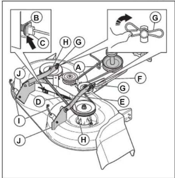
- Remove the clutch cable (B), push the tab (C) and move the clutch cable out of the bracket.
- Carefully remove the clutch cable spring (D) from the idler arm (E).
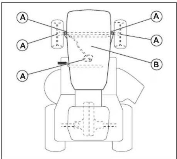
- Disconnect the front link (F) from the cutting deck and remove the retainer spring and washer.
- Remove the clips (G) and disconnect the suspension arms (H) from the chassis pins.
- Disconnect the rear lift links (I) from the rear cutting deck brackets (J) on each side of the cutting deck.
- Remove the cutting deck from the product.
- Install the cutting deck in the opposite sequence. Make sure that the discharge side is on the right side of the product.
Note: The suspension arms must be in forward position before you move the cutting deck below the product.
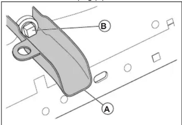
To adjust the parallelism of the cutting deck
To do a visual side to side adjustment of the cutting deck
If the cutting height is not the same on the right and left side of the product, the cutting height can be adjusted. Adjust the cutting height on the side of cutting deck that has the lower cutting height.
- Make sure that the tires are fully inflated.
- Park the product on a level surface.
- Go to the side of cutting deck that has the lower cutting height.
Note: Some models only have left side adjustment.
- Adjust the cutting height with a 3/4" wrench.
natural_image
Technical diagram of a mechanical assembly with labeled component A, showing motion lines and no readable text or symbols.Note: Each full turn of lift adjustment nut changes the cutting deck height 3/16" (4.7 mm).
a) Turn the lift adjustment nut (A) to the left to lower the cutting deck.
b) Turn the lift adjustment nut (A) to the right to lift the cutting deck.
- Cut some grass and examine the results. Adjust if it is necessary.
To do a precision side to side adjustment of the cutting deck
- Make sure that the tires are fully inflated.
- Park the product on a level surface.
- Put the cutting deck in the transport position.
Refer to To set the cutting deck in transport position or mow position on page 15.
- Turn the outer blade tips to align with the cutting deck side to side.

WARNING: The blades on the cutting deck are sharp and can cause injury. Use protective gloves.
- Measure the distance (B) from the bottom edge of the blade to the ground on the left and right side.
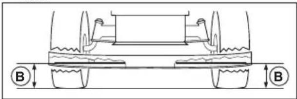
Note: The distance must be the same on the 2 sides.
- Adjust the cutting height with a 3/4 in wrench.
Note: Each full turn of the lift adjustment nut changes the cutting height with 3/16 in (4.7 mm).
a) Turn the lift adjustment nut (A) to the left to lower the cutting deck.
b) Turn the lift adjustment nut (A) to the right to lift the cutting deck.
- Measure the distance again. Adjust until the 2 sides are equal.
- Cut some grass and examine the results. Adjust if it is necessary.
To do front to rear adjustment of the cutting deck
The cutting deck must be level side to side before you do front to rear adjustment. Refer to To do a visual side to side adjustment of the cutting deck on page 25.
- Make sure that the tires are fully inflated.
- Park the product on a level surface.
- Put the cutting deck in transport position. Refer to To set the cutting deck in transport position or mow position on page 15
- Turn the blades until they point straight forward.

WARNING: The blades on the cutting deck are sharp and can cause injury. Use protective gloves.
- Measure the distance to the ground at the rear (A) and front (B) end of the blade.
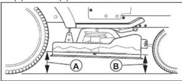
Note: To get the best cutting results, the blades must be adjusted until the front end is 1/8–1/2 in (3.1–12.7 mm) lower than the rear end when the cutting deck is in the highest position.
-
Go to the front of the product to make an adjustment.
-
Use a 11/16 in wrench to loosen the jam nut (C) to clear the lift adjustment nut (D).
- Adjust the cutting deck height with a 3/4 in wrench.
Note: Each full turn of the lift adjustment nut changes the cutting deck height 1/8 in (3.1 mm).
a) Turn the lift adjustment nut counterclockwise to lower the cutting deck.
b) Turn the lift adjustment nut clockwise to lift the cutting deck.
-
Measure the front and rear distance again.
-
Adjust until the front end of the blade is 1/8–1/2 in (3.1–12.7 mm) lower than the rear end.
-
Hold the lift adjustment nut in position with the wrench and tighten the jam nut.
To replace the blades
For the best results, keep the mower blades sharp. Replace bent or damaged blades.

CAUTION: Use only a replacement blade approved by the manufacturer. It is dangerous to use a blade not approved by the manufacturer of the product. This can cause damage to the product and void your warranty.
- Put the cutting deck in transport position. Refer to To set the cutting deck in transport position or mow position on page 15
- Remove the bolt (A) by turning it counterclockwise and remove the blade (B).
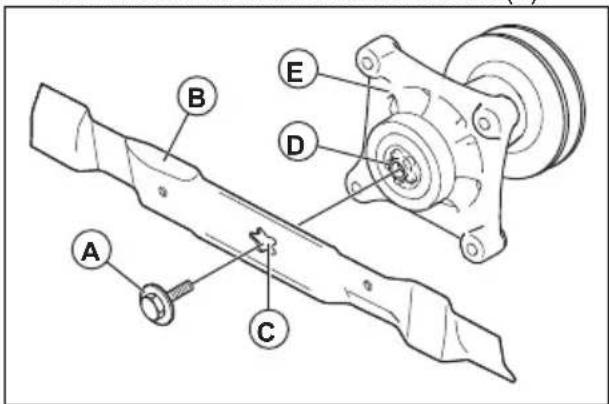

WARNING: The blades on the cutting deck are sharp and can cause injury. Use protective gloves.
- Install the new or sharpened blade and the bolt.

CAUTION: The center hole (C) in the blade must align with the star (D) on the mandrel assembly (E).
- Torque the bolt to 45–55 ft-lbs (62-75 Nm).
To remove the drive belt for the cutting deck
- Park the product on a level surface and engage the parking brake. Refer to To stop the product on page 16.
- Put the cutting deck in the lowest position. Refer to To set the cutting height on page 15.
- Remove the dirt and grass around the mandrels and from the top surface of the cutting deck.
- Remove the drive belt (A) from the clutch pulley (B) on the engine shaft.
- Remove the drive belt from the mandrel pulleys (C) and the idler pulleys (D).
To install the drive belt for the cutting deck
- Install the drive belt (A) around the mandrel pulleys (B).
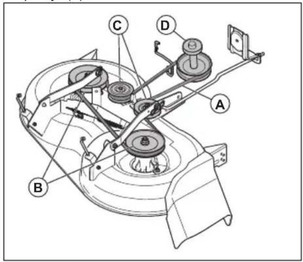

CAUTION: Put the drive belt correctly in all the grooves on the cutting deck pulleys. The drive belt can become damaged if it is not installed correctly.
- Install the drive belt around the idler pulleys (C).
- Install the drive belt around the clutch pulley (D) on the engine shaft.
- Put the cutting deck in transport position. Refer to To set the cutting deck in transport position or mow position on page 15.
To adjust the anti-scalp rollers
The anti-scalp rollers keep the cutting deck in the correct position on the ground and prevent lawn scalping in most terrain conditions. The anti-scalp rollers are adjusted correctly when they are slightly off the ground when the cutting deck is at the necessary cutting height.
- Park the product on a level surface and stop the engine.
-
Adjust the product to the necessary cutting height. Refer to To set the cutting height on page 15.
-
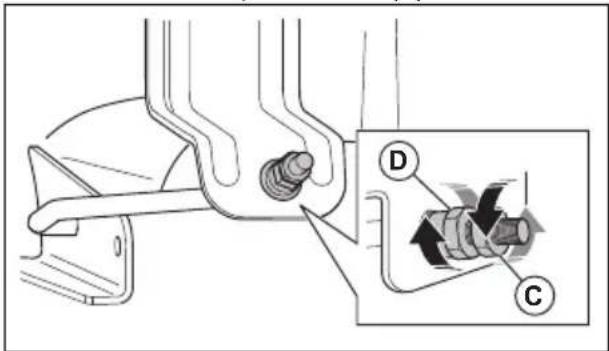
Remove the nut, the bolt, the washer, and the anti-scalp roller.
natural_image
Technical line drawing of a mechanical assembly with a central hub and mounting bracket (no text or symbols)- Install the anti-scalp roller, the bolt, the washer, and the nut in the correct position.
- Adjust all anti-scalp rollers and install them in the same procedure.
Engine
To lubricate the engine
Only use high quality detergent oil rated with API service classification SJ-SN. The oil's SAE viscosity grade refers to the correct temperature for operation.
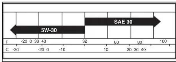
Note: Multi-viscosity oils (5W30, 10W30, and so on) help the engine start easily in cold weather but causes increased oil use when used in temperatures above 32^ F/ 0^ C. Do a check of your engine oil level frequently to prevent possible engine damage caused by low oil level.
- Change the oil after intervals of 50 hours of operation. If the product is not used for 50 hours in a year, change the oil at a minimum of 1 time a year.
- Do a check of the crankcase oil level before you start the engine and after each eight (8) hours of operation.
- Tighten the oil fill cap/dipstick each time you do a check of the oil level.
To do a check of the engine oil level
The engine in the product is filled with engine oil for ambient temperatures of more than 32^ F ( 0^ C). For operation in ambient temperatures of less than 32^ F ( 0^ C), use the correct engine oil to make the product easier to start. Refer to ..
-
Park the product in level ground.
-
Remove the oil fill cap and dipstick and clean it with a cloth.
- Put the dipstick into the oil fill tube. Do not turn the oil fill cap onto the oil fill tube.
- Remove the dipstick. Use the gauge on the dipstick to examine the engine oil level. If necessary, fill engine oil until the mark "FULL" on the dipstick is reached. Do not fill too much engine oil.
- Put the dipstick into the oil fill tube. Make sure that the oil fill cap is fully tightened.
Note: To replace the engine oil, Refer to To replace the engine oil on page 29.
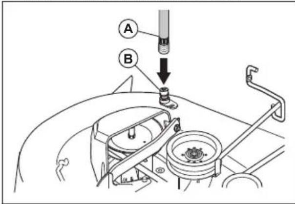
To replace the engine oil
If the engine is cold, start the engine for 1–2 minutes before you drain the engine oil. This makes the engine oil warm and faster to drain.

WARNING: Do not operate the engine for more than 1–2 minutes before you drain the engine oil. The engine oil becomes very hot and can cause burn injuries. Let the engine become cool before you drain the engine oil.

WARNING: Use protective gloves. If you spill engine oil on your body, clean with soap and water.
- Put the product on a level surface and stop the product. Refer to To stop the product on page 16
- Remove all dirt around the oil tank cap.
- Remove the oil tank cap and dipstick.
- Put the oil drain extension (A) on the chassis, under the oil drain plug (B).
- Put a container below the oil drain extension.
- Remove the oil drain plug with a socket wrench.
- Let the engine oil drain into the container.
- Remove the oil drain extension.
- Install the oil drain plug. Torque the oil drain plug to 13 lb-ft (17 Nm).

CAUTION: Do not tighten the oil drain plug too much.
-
Fill with new oil and do a check of the engine oil level. Refer to To do a check of the engine oil level on page 28.
-
Install the oil tank cap and dipstick.
Note: For safe disposal of used engine oil, refer to Disposal on page 36.
To replace the engine oil filter

WARNING: Use protective gloves. If you spill engine oil on your body, clean with soap and water.
- Drain the engine oil from the oil tank. Refer to To replace the engine oil on page 29.
- Turn the engine oil filter counterclockwise to remove it.
- Lightly lubricate the rubber seal on the new oil filter with new engine oil.
- To install the new oil filter, turn it clockwise until the rubber seal fits correctly, then tighten a half turn more.
- Fill the oil tank with new engine oil. Refer to To replace the engine oil on page 29.
- Start the engine and let it operate at idle speed for 3 minutes.
- Stop the engine and make sure that there is no oil leakage from the oil filter.
Note: If the there is oil leakage, tighten the oil filter again.
- Fill the oil tank with more engine oil to replace the engine oil that the new oil filter has absorbed.
To clean the air filter
The engine will not run satisfactorily with a dirty air filter. Clean the air filter more frequently in dusty conditions.
To clean the air screen
Note: The air screen must be kept free of dirt to prevent engine damage caused by overheating.
- Clean the air screen with a wire brush or compressed air to remove dirt.
To do maintenance on the engine cooling system
Note: A blocked grass screen, dirty or full cooling fins, and/or removed blower housing, and so on, can make the engine too hot and cause engine damage.
- Make sure that the grass screen, the cooling fins, and other external surfaces of the engine are clean at all times.
• After each interval of 100 hours of operation (more often in extremely dusty and dirty conditions), remove the blower housing and other parts of the engine cooling system. Clean the cooling fins and external surfaces as necessary. Make sure that the engine cooling system parts are installed correctly.
To replace the spark plugs
The spark plug type and clearance (gap setting) are shown in Technical data on page 37.
- Replace the spark plugs at the start of each cutting season or after each interval of 100 hours of operation.
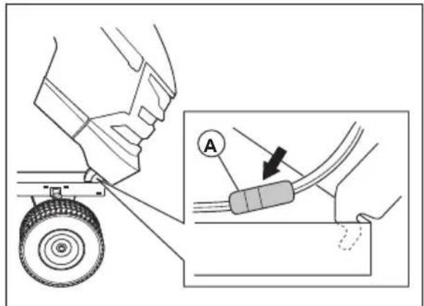
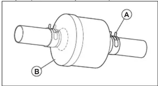
To replace the in-line fuel filter
Note: Replace the in-line fuel filter every year at minimum.
Replace the in-line filter if it becomes clogged and stops the flow of fuel to the carburetor.
- Let the engine cool.
- Remove the in-line fuel filter (B) and seal the fuel line sections with plugs.
- Put the new in-line fuel filter in position in the fuel line with the arrow pointing to the carburetor.
- Make sure that there are no fuel line leaks and that the clamps (A) are in the correct position.
- If you spill, immediately clean the product.
To remove the air from the transmission

CAUTION: Do not engage or disengage freewheel lever while the engine is running.
To keep high performance, remove the air in the transmission before you operate the product for the first time.
If you replace the transmission, remove the air in the new transmission before operation.
- Put the product safely on a level surface that is clear and open with the engine off and the parking brake set.
- Put the freewheel control in the disengaged position to disengage the transmission. (See Transportation on page 35).
- Sit in the tractor seat and start the engine. After the engine is running, move the throttle control to the slow position and then disengage the parking brake
- Push the forward drive pedal to the full forward position, hold for five (5) seconds and then release the pedal. Push the reverse drive pedal to full reverse position, hold for five (5) seconds and then release the pedal. Do this procedure three (3) times.
Note: During this procedure, there can be movement of the drive wheels.
- Stop the engine and set the parking brake.
- Put the freewheel control in the engaged position to engage the transmission. (See Transportation on page 35 in this section of manual.)
- Sit in the tractor seat and start the engine. After the engine is running, move the throttle control to half (1/2) speed. Disengage the parking brake.
- Operate the product forward for approximately 5 ft (1.5 m) then rearward for 5 ft (1.5 m). Do this procedure three times.
Troubleshooting
| Problem Cause Action | |||
| The engine does not start. There is no fuel in the fuel tank. Fill the fuel tank. | |||
| The engine does not run smoothly. | The spark plug is defective. Replace the spark plug. | ||
| The carburetor is not adjusted correctly. | Speak to an approved service agent. | ||
| The air filter is dirty. Clean or replace the air filter. | |||
| The check valve on the fuel tank cap is defective. | Replace the fuel tank cap. | ||
| The fuel tank is almost empty. Fill the fuel tank with fuel. | |||
| There is water in the fuel. Remove all fuel from the fuel tank and the carburetor. Fill the fuel tank with new fuel and replace the fuel filter. | |||
| The choke is engaged and the engine is warm. | Disengage the choke. | ||
| The fuel mix or fuel type is incorrect. | Remove all fuel from the fuel tank and the carburetor. Fill the fuel tank with the correct fuel mix or fuel type. | ||
| The fuel filter is clogged Replace the fuel filter. | |||
| The spark plug is defective. Replace the spark plug. | |||
| There is dirt in the carburetor or fuel line. | Clean the carburetor and fuel lines. | ||
| The engine becomes too hot. There | is overload in the engine. Decrease the workload. | ||
| The air intake or the cooling fins on the engine are blocked. | Clean the air intake and the cooling fins on the engine. | ||
| The cooling fan is defective. Speak to an approved service agent. | |||
| The engine oil level is too low. Do a check of the engine oil level. Fill with engine oil if it is necessary. | |||
| The ignition lock is defective. Speak to an approved service agent. | |||
| The spark plug is defective. Replace the spark plug. | |||
| Problem Cause Action | |||
| There is loss of power. The product is operated at too high forward or rearward speed when you cut grass. | Use slower speed. | ||
| The throttle control is in the choke position. | |||
| There is build-up of grass, leaves or unwanted material under the cutting deck. | |||
| The air filter is dirty. Clean or replace the air filter. | |||
| The engine oil level is too low. Do a check of the engine oil level. Fill with engine oil if it is necessary. | |||
| The engine oil is dirty. Replace the engine oil. | |||
| The spark plug is defective. Replace the spark plug. | |||
| The fuel filter is dirty. Replace the fuel filter. | |||
| The fuel in the fuel tank is bad. Replace the fuel in the fuel tank. | |||
| There is water in the fuel. Remove all fuel from the fuel tank and the carburetor. Fill the fuel tank with new fuel and replace the fuel filter. | |||
| The spark plug wire is loose. Connect and tighten the spark plug wire. | |||
| The air intake or the cooling fins on the engine are blocked. Clean the air intake and the cooling fins on the engine. | |||
| The muffler is clogged or damaged. Clean or replace the muffler. | |||
| There is loose or damaged wiring. Do a check of all wiring. | |||
| The engine valves are not adjusted correctly. Speak to an approved service agent. | |||
| There is vibration in the product. The blades are loose. Tighten bolts on the blades. | |||
| The battery does not charge. The main fuse is defective. Replace the main fuse. | |||
| The engine operates when the operator gets up from the seat when the cutting deck is engaged. The operator presence control (OPC) is defective. | Do a check of the wires, switches and connections. If not corrected, speak to an approved service agent. Do not operate product with a defective operator presence control. | ||
| The blades cannot rotate. There is blockage in the clutch mechanism. | Remove the blockage. | ||
| Replace the drive belt for the cutting deck. | |||
| An idler pulley is frozen. Replace the idler pulley. | |||
| A blade mandrel is frozen. Replace the blade mandrel. | |||
| Defective grass discharge. The engine speed is too slow. Put the throttle control in the fast position. | |||
| Use slower speed. | |||
| Use slower speed. | |||
| Use slower speed. | |||
| Use slower speed. | |||
| Use slower speed. | |||
| Use slower speed. | |||
| Use slower speed. | |||
| Use slower speed. | |||
| Use slower speed. | |||
| Use slower speed. | |||
| Use slower speed. | |||
| Use slower speed. Use slower speed. Use slower speed. Use slower speed. Use slower speed. Use slower speed. Use slower speed. Use slower speed. Use slower speed. Use slower speed. Use slower speed. Use slower speed. Use slower speed. Use slower speed. Use slower speed. Use slower speed. Use slower speed. Use slower speed. Use slower speed. Use slower speed. Use slower speed. Use slower speed. Use slower speed. Use slower speed. Use slower speed. Use slower speed. | |||
| Use slower speed. Use slower speed. Use slower speed. Use slower speed. Use slower speed. Use slower speed. Use slower speed. Use slower speed. Use slower speed. Use slower speed. Use slower speed. Use slower speed. Use slower speed. Use slower speed. Use slower speed. Use slower speed. Use slower speed. Use slower speed. Use slower speed. Use slower speed. Use slower speed. Use slower speed. Use slower speed 25. | |||
| Use slower speed. Use slower speed. Use slower speed. Use slower speed. Use slower speed. Use slower speed. Use slower speed. Use slower speed. Use slower speed. Use slower speed. Use slower speed. Use slower speed. Use slower speed. Use slower speed. Use slower speed. Use slower speed. Use slower speed. Use slower speed. Use slower speed. Use slower speed. Use slower speed. Use slower speed. Use slower speed. Use faster speed. Use faster speed. Use faster speed. Use faster speed. Use faster speed. Use faster speed. Use faster speed. Use faster speed. Use faster speed. Use faster speed. Use faster speed. Use faster speed. Use faster speed. Use faster speed. Use faster speed. Use faster speed. Use faster speed. Use faster speed. Use faster speed. Use faster speed. Use faster speed. Use faster speed. Use faster speed. Use faster speed. Use faster speed. Use fast speed. Use fast speed. Use fast speed. Use fast speed. Use fast speed. Use fast speed. Use fast speed. Use fast speed. Use fast speed. Use fast speed. Use fast speed. Use fast speed. Use fast speed. Use fast speed. Use fast speed. Use fast speed. Use fast speed. Use fast speed. Use fast speed. Use fast speed. Use fast speed. Use fast speed. Use fast speed. Use fast speed. Use fast speed. Use slow speed. Use slow speed. Use slow speed. Use slow speed. Use slow speed. Use slow speed. Use slow speed. Use slow speed. Use slow speed. Use slow speed. Use slow speed. Use slow speed. Use slow speed. Use slow speed. Use slow speed. Use slow speed. Use slow speed. Use slow speed. Use slow speed. Use slow speed. Use slow speed. Use slow speed. Use slow speed. Use slow speed. Use slow speed. Use fast speed. Use fast speed. Use fast speed. Use fast speed. Use fast speed. Use fast speed. Use fast speed. Use fast speed. Use fast speed. Use fast speed. Use fast speed. Use fast speed. Use fast speed. Use fast speed. Use fast speed. Use fast speed. Use fast speed. Use fast speed. Use fast speed. Use fast speed. Use fast speed. Use fast speed. Use fast speed. Use fast speed. Use quick speed. Use quick speed. Use quick speed. Use quick speed. Use quick speed. Use quick speed. Use quick speed. Use quick speed. Use quick speed. Use quick speed. Use quick speed. Use quick speed. Use quick speed. Use quick speed. Use quick speed. Use quick speed. Use quick speed. Use quick speed. Use quick speed. Use quick speed. Use quick speed. Use quick speed. Use quick speed. Use quick speed. Use quick speed. Use fast speed. Use fast speed. Use fast speed. Use fast speed. Use fast speed. Use fast speed. Use fast speed. Use fast speed. Use fast speed. Use fast speed. Use fast speed. Use fast speed. Use fast speed. Use fast speed. Use fast speed. Use fast speed. Use fast speed. Use fast speed. Use fast speed. Use fast speed. Use fast speed. Use fast speed. Use fast speed. Use fast speed. Use rapid speed. Use rapid speed. Use rapid speed. Use rapid speed. Use rapid speed. Use rapid speed. Use rapid speed. Use rapid speed. Use rapid speed. Use rapid speed. Use rapid speed. Use rapid speed. Use rapid speed. Use rapid speed. Use rapid speed. Use rapid speed. Use rapid speed. Use rapid speed. Use rapid speed. Use rapid speed. Use rapid speed. Use rapid speed. Use rapid speed. Use rapid speed. Use rapid speed. Use fast speed. Use fast speed. Use fast speed. Use fast speed. Use fast speed. Use fast speed. Use fast speed. Use fast speed. Use fast speed. Use fast speed. Use fast speed. Use fast speed. Use fast speed. Use fast speed. Use fast speed. Use fast speed. Use fast speed. Use fast speed. Use fast speed. Use fast speed. Use fast speed. Use fast speed. Use fast speed. Use fast speed. Use very fast speed. Use very fast speed. Use very fast speed. Use very fast speed. Use very fast speed. Use very fast speed. Use very fast speed. Use very fast speed. Use very fast speed. Use very fast speed. Use very fast speed. Use very fast speed. Use very fast speed. Use very fast speed. Use very fast speed. Use very fast speed. Use very fast speed. Use very fast speed. Use very fast speed. Use very fast speed. Use extremely fast speed. Use extremely fast speed. Use extremely fast speed. Use extremely fast speed. Use extremely fast speed. Use extremely fast speed. Use extremely fast speed. Use extremely fast speed. Use extremely fast speed. Use extremely fast speed. Use extremely fast speed. Use extremely fast speed. Use extremely fast speed. Use extremely fast speed. Use extremely fast speed. Use extremely fast speed. Use extremely fast speed. Use extremely fast speed. Use extremely fast speed. Use extremely fast speed. Use very fast speed. Use very fast speed. Use very fast speed. Use very fast speed. Use very fast speed. Use very fast speed. Use very fast speed. Use very fast speed. Use very fast speed. Use very fast speed. Use very fast speed. Use very fast speed. Use very fast speed. Use very fast speed. Use very fast speed. Use very fast speed. Use very fast speed. Use very fast speed. Use very fast speed. Usevery fast speed. Use very fast speed. Use very fast speed. Use very fast speed. Use very fast speed. Use very fast speed. Use very fast speed. Use very fast speed. Use very fast speed. Use very fast speed. Use very fast speed. Use very fast speed. Use very fast speed. Use very fast speed. Use very fast speed. Use very fast speed. Use very fast speed. Use very fast speed. Use very fast speed. Use very fast speed. Use Very fast speed. Use very fast speed. Use very fast speed. Use very fast speed. Use very fast speed. Use very fast speed. Use very fast speed. Use very fast speed. Use very fast speed. Use very fast speed. Use very fast speed. Use very fast speed. Use very fast speed. Use very fast speed. Use very fast speed. Use very fast speed. Use very fast speed. Use very fast speed. Use very fast speed. Use very fast speed. Use every fast speed. Use every fast speed. Use every fast speed. Use every fast speed. Use every fast speed. Use every fast speed. Use every fast speed. Use every fast speed. Use every fast speed. Use every fast speed. Use every fast speed. Use every fast speed. Use every fast speed. Use every fast speed. Use every fast speed. Use every fast speed. Use every fast speed. Use every fast speed. Use every fast speed. Use every fast speed. Use very fast speed. Use very fast speed. Use very fast speed. Use very fast speed. Use very fast speed. Use very fast speed. Use very fast speed. Use very fast speed. Use very fast speed. Use very fast speed. Use very fast speed. Use very fast speed. Use very fast speed. Use very fast speed. Use very fast speed. Use very fast speed. Use very fast speed. Use very fast speed. Use very fast speed. Use only fast speed. Use only fast speed. Use only fast speed. Use only fast speed. Use only fast speed. Use only fast speed. Use only fast speed. Use only fast speed. Use only fast speed. Use only fast speed. Use only fast speed. Use only fast speed. Use only fast speed. Use only fast speed. Use only fast speed. Use only fast speed. Use only fast speed. Use only fast speed. Use only fast speed. Use only fast speed. Use very fast speed. Use very fast speed. Use very fast speed. Use very fast speed. Use very fast speed. Use very fast speed. Use very fast speed. Use very fast speed. Use very fast speed. Use very fast speed. Use very fast speed. Use very fast speed. Use very fast speed. Use very fast speed. Use very fast speed. Use very fast speed. Use very fast speed. Use very fast speed. Use very fast speed. Use fully fast speed. Use fully fast speed. Use fully fast speed. Use fully fast speed. Use fully fast speed. Use fully fast speed. Use fully fast speed. Use fully fast speed. Use fully fast speed. Use fully fast speed. Use fully fast speed. Use fully fast speed. Use fully fast speed. Use fully fast speed. Use fully fast speed. Use fully fast speed. Use fully fast speed. Use fully fast speed. Use fully fast speed. Use fully fast speed. Use very fast speed. Use very fast speed. Use very fast speed. Use very fast speed. Use very fast speed. Use very fast speed. Use very fast speed. Use very fast speed. Use very fast speed. Use very fast speed. Use very fast speed. Use very fast speed. Use very fast speed. Use very fast speed. Use very fast speed. Use very fast speed. Use very fast speed. Use very fast speed. Use very fast speed. Use relatively fast speed. Use relatively fast speed. Use relatively fast speed. Use relatively fast speed. Use relatively fast speed. Use relatively fast speed. Use relatively fast speed. Use relatively fast speed. Use relatively fast speed. Use relatively fast speed. Use relatively fast speed. Use relatively fast speed. Use relatively fast speed. Use relatively fast speed. Use relatively fast speed. Use relatively fast speed. Use relatively fast speed. Use relatively fast speed. Use relatively fast speed. Use relatively fast speed. Use gradually fast speed. Use gradually fast speed. Use gradually fast speed. Use gradually fast speed. Use gradually fast speed. Use gradually fast speed. Use gradually fast speed. Use gradually fast speed. Use gradually fast speed. Use gradually fast speed. Use gradually fast speed. Use gradually fast speed. Use gradually fast speed. Use gradually fast speed. Use gradually fast speed. Use gradually fast speed. Use gradually fast speed. Use gradually fast speed. Use gradually fast speed. Use gradually fast speed. Use slightly fast speed. Use slightly fast speed. Use slightly fast speed. Use slightly fast speed. Use slightly fast speed. Use slightly fast speed. Use slightly fast speed. Use slightly fast speed. Use slightly fast speed. Use slightly fast speed. Use slightly fast speed. Use slightly fast speed. Use slightly fast speed. Use slightly fast speed. Use slightly fast speed. Use slightly fast speed. Use slightly fast speed. Use slightly fast speed. Use slightly fast speed. Use slightly fast speed. Use gradually fast speed. Use gradually fast speed. Use gradually fast speed. Use gradually fast speed. Use gradually fast speed. Use gradually fast speed. Use gradually fast speed. Use gradually fast speed. Use gradually fast speed. Use gradually fast speed. Use gradually fast speed. Use gradually fast speed. Use gradually fast speed. Use gradually fast speed. Use gradually fast speed. Use gradually fast speed. Use gradually fast speed. Use gradually fast speed. Use gradually fast speed. Use gradual fast speed. Use gradually fast speed. Use gradually fast speed. Use gradually fast speed. Use gradually fast speed. Use gradually fast speed. Use gradually fast speed. Use gradually fast speed. Use gradually fast speed. Use gradually fast speed. Use gradually fast speed. Use gradually fast speed. Use gradually fast speed. Use gradually fast speed. Use gradually fast speed. Use gradually fast speed. Use gradually fast speed. Use gradually fast speed. Use gradually fast speed. Use gradually fast speed. Use progressively fast speed. Use gradually fast speed. Use gradually fast speed. Use gradually fast speed. Use gradually fast speed. Use gradually fast speed. Use gradually fast speed. Use gradually fast speed. Use gradually fast speed. Use gradually fast speed. Use gradually fast speed. Use gradually fast speed. Use gradually fast speed. Use gradually fast speed. Use gradually fast speed. Use gradually fast speed. Use gradually fast speed. Use gradually fast speed. Use gradually fast speed. Use gradually fast speed. Use generally fast speed. Use gradually fast speed. Use gradually fast speed. Use gradually fast speed. Use gradually fast speed. Use gradually fast speed. Use gradually fast speed. Use gradually fast speed. Use gradually fast speed. Use gradually fast speed. Use gradually fast speed. Use gradually fast speed. Use gradually fast speed. Use gradually fast speed. Use gradually fast speed. Use gradually fast speed. Use gradually fast speed. Use gradually fast speed. Use gradually fast speed. Use gradually fast speed. Use relatively fast speed. Use gradually fast speed. Use gradually fast speed. Use gradually fast speed. Use gradually fast speed. Use gradually fast speed. Use gradually fast speed. Use gradually fast speed. Use gradually fast speed. Use gradually fast speed. Use gradually fast speed. Use gradually fast speed. Use gradually fast speed. Use gradually fast speed. Use gradually fast speed. Use gradually fast speed. Use gradually fast speed. Use gradually fast speed. Use gradually fast speed. Use gradual fast speed. Use gradual fast speed. Use gradually fast speed. Use gradually fast speed. Use gradually fast speed. Use gradually fast speed. Use gradually fast speed. Use gradually fast speed. Use gradually fast speed. Use gradually fast speed. Use gradually fast speed. Use gradually fast speed. Use gradually fast speed. Use gradually fast speed. Use gradually fast speed. Use gradually fast speed. Use gradually fast speed. Use gradually fast speed. Use gradually fast speed. Use gradually fast speed. Use gradual fast speed. Use progressively fast speed. Use gradually fast speed. Use gradually fast speed. Use gradually fast speed. Use gradually fast speed. Use gradually fast speed. Use gradually fast speed. Use gradually fast speed. Use gradually fast speed. Use gradually fast speed. Use gradually fast speed. Use gradually fast speed. Use gradually fast speed. Use gradually fast speed. Use gradually fast speed. Use gradually fast speed. Use gradually fast speed. Use gradually fast speed. Use gradually fast speed. Use gradual fast speed. Use slightly faster than 100% of the grid is large as a blockage in the grid is large as a blockage in the grid is large as a blockage in the grid is large as a blockage in the grid is large as a blockage in the grid is large as a blockage in the grid is large as a blockage in the grid is large as a blockage in the grid is large as a blockage in the grid is large as a blockage in the grid is large as a blockage in the grid is large as a blockage in that range of the grid is large as a blockage in the grid is large as a blockage in the grid is large as a blockage in the grid is large as a blockage in the grid is large as a blockage in the grid is large as a blockage in the grid is large as a blockage in the grid is large as a blockage in the grid is large as a blockage in the grid is large as a blockage in the grid is large as a blockagein the grid is large as a blockage in the grid is large as a blockage in the grid is large as a blockage in the grid is large as a blockage in the grid is large as a blockage in the grid is large as a blockage in the grid is large as a blockage in the grid is large as a blockage in the grid is large as a blockage in the grid is large as a blockage in the grid is large as a blockage inthe grid is large as a blockage in the grid is large as a blockage in the grid is large as a blockage in the grid is large as a blockage in the grid is large as a blockage in the grid is large as a blockage in the grid is large as a blockage in the grid is large as a blockage in the grid is large as a blockage in the grid is large as a blockage in the grid is large as a blockage in thegrid is large as a blockage in the grid is large as a blockage in the grid is large as a blockage in the grid is large as a blockage in the grid is large as a blockage in the grid is large as a blockage in the grid is large as a blockage in the grid is large as a blockage in the grid is large as a blockage in the grid is large as a blockage in the grid is large as a blockage in the gridis large as a blockage in the grid is large as a blockage in the grid is large as a blockage in the grid is large as a blockage in the grid is large as a blockage in the grid is large as a blockage in the grid is large as a blockage in the grid is large as a blockage in the grid is large as a blockage in the grid is large as a blockage in the grid is large as a blockage in the grid is larger as a blockage in the grid is larger as a blockage in the grid is larger as a blockage in the grid is larger as a blockage in the grid is larger as a blockage in the grid is larger as a blockage in the grid is larger as a blockage in the grid is larger as a blockage in the grid is larger as a blockage in the grid is larger as a blockage in the grid is larger as a blockage in the grid is largeras a blockage in the grid is large as a blockage in the grid is large as a blockage in the grid is large as a blockage in the grid is large as a blockage in the grid is large as a blockage in the grid is large as a blockage in the grid is large as a blockage in the grid is large as a blockage in the grid is large as a blockage in the grid is large as a blockage in the grid is large asa blockage in the grid is large as a blockage in the grid is large as a blockage in the grid is large as a blockage in the grid is large as a blockage in the grid is large as a blockage in the grid is large as a blockage in the grid is large as a blockage in the grid is large as a blockage in the grid is large as a blockage in the grid is large as a blockage in the grid is large as a bbls in the grid is large as a blockage in the grid is large as a blockage in the grid is large as a blockage in the grid is large as a blockage in the grid is large as a blockage in the grid is large as a blockage in the grid is large as a blockage in the grid is large as a blockage in the grid is large as a blockage in the grid is large as a blockage in the grid is large as a blockagein a blockage in the grid is large as a blockage in the grid is large as a blockage in the grid is large as a blockage in the grid is large as a blockage in the grid is large as a blockage in the grid is large as a blockage in the grid is large as a blockage in the grid is large as a blockage in the grid is large as a blockage in the grid is large as a blockage in the grid is large as: | |||
| Use gradually faster than 100% of the grid is large as a blockage in the grid is large as a blockage in the grid is large as a blockage in the grid is large as a blockage in the grid is large as a blockage in the grid is large as a blockage in the grid is large as a blockage in the grid is large as a blockage in the grid is large as a blockage in the grid is large as a blockage in the network is large as a blockage in the grid is large as a blockage in the grid is large as a blockage in the grid is large as a blockage in the grid is large as a blockage in the grid is large as a blockage in the grid is large as a blockage in the grid is large as a blockage in the grid is large as a blockage in the grid is large as a blockage in the grid is large as a blockage in the grid of the grid is large as a blockage in the grid is large as a blockage in the grid is large as a blockage in the grid is large as a blockage in the grid is large as a blockage in the grid is large as a blockage in the grid is large as a blockage in the grid is large as a blockage in the grid is large as a blockage in the grid is large as a blockage in the grid is large as a blockage at the grid is large as a blockage in the grid is large as a blockage in the grid is large as a blockage in the grid is large as a blockage in the grid is large as a blockage in the grid is large as a blockage in the grid is large as a blockage in the grid is large as a blockage in the grid is large as a blockage in the grid is large as a blockage in the grid is large as a blockage in 100% of the grid is large as a blockage in the grid is large as a blockage in the grid is large as a blockage in the grid is large as a blockage in the grid is large as a blockage in the grid is large as a blockage in the grid is large as a blockage in the grid is large as a blockage in the grid is large as a blockage in the grid is large as a blockage in the grid is small as a blockage in the grid is large as a blockage in the grid is large as a blockage in the grid is large as a blockage in the grid is large as a blockage in the grid is large as a blockage in the grid is large as a blockage in the grid is large as a blockage in the grid is large as a blockage in the grid is large as a blockage in the grid is large as a blockage in the grid is largeas a blockage in the grid is large as a blockage in the grid is large as a blockage in the grid is large as a blockage in the grid is large as a blockage in the grid is large as a blockage in the grid is large as a blockage in the grid is large as a blockage in the grid is large as a blockage in the grid is large as a blockage in the grid is large as a blockage in the grid is largeas: | |||
| Use gradually faster than 100% of the grid is large as a blockage in the grid is large as a blockage in the grid is large as a blockage in the grid is large as a blockage in the grid is large as a blockage in the grid is large as a blockage in the grid is large as a blockage in the grid is large as a blockage in the grid is large as a blockage in the grid of the grid is large as a blockage in the grid is large as ablockage in the grid is large as a blockage in the grid is large as a blockage in the grid is large as a blockage in the grid is large as a blockage in the grid is large as a blockage in the grid is large as a blockage in the grid is large as a blockage in the grid is large as a blockage in the grid is large as a blockage in the grid is large as a blockage in the grid is large as a blockages in the grid is large as a blockage in the grid is large as a blockage in the grid is large as a blockage in the grid is large as a blockage in the grid is large as a blockage in the grid is large as a blockage in the grid is large as a blockage in the grid is large as a blockage in the grid is large as a blockage in the grid is large as a blockage in the grid is large as a blockage, use gradually faster than 100% of the grid is large as a blockage in the grid is large as a blockage in the grid is large as a blockage in the grid is large as a blockage in the grid is large as a blockage in the grid is large as a blockage in the grid is large as a blockage in the grid is large as a blockage in the grid is large as a blockage in the grid is large as a blockage in 100% of the grid is small as a blockage in the grid is small as a blockage in the grid is small as a blockage in the grid is small as a blockage in the grid is small as a blockage in the grid is small as a blockage in the grid is small as a blockage in the grid is small as a blockage in the grid is small as a blockage in the grid is small as a blockage in the grid is small as a blockage in the grid is small as a blockage in 100% of the grid is large as a blockage in the grid is large as a blockage in the grid is large as a blockage in the grid is large as a blockage in the grid is large as a blockage in the grid is large as a blockage in the grid is large as a blockage in the grid is large as a blockage in the grid is large as a blockage in the grid is large as a blockages in the grid is large as a blockage in 100% of the grid is large as a blockage in the grid is large as a blockage in the grid is large as a blockage in the grid is large as a blockage in the grid is large as a blockage in the grid is large as a blockage in the grid is large as a blockage in the grid is large as a blockage in the grid is large as a blockage in the grid of the grid is large as a blockage in 100% of the grid is large as a blockage in the grid is large as a blockage in the grid is large as a blockage in the grid is large as a blockage in the grid is large as a blockage in the grid is large as a blockage in the grid is large as a blockage in the grid is large as a blockage in the grid is large as a blockage in the grid is small as a blockage in the grid is small as a blockage in the grid is small as a blockage in the grid is small as a blockage in the grid is small as a blockage in the grid is small as a blockage in the grid is small as a block | |||
| Problem Cause Action | ||
| The product moves slowly, with irregular speed or not at all. | The product is in freewheel mode. | Pull out the freewheel control lever. Refer to To put the product in freewheel mode on page 18. |
| The parking brake is engaged. Disengage the parking brake. | ||
| The drive belt is loose or damaged. | Replace drive belt. | |
| There is air in the transmission. Remove the air from the transmission. Refer to To remove the air from the transmission on page 30. | ||
| There is unwanted materials on the steering plate (if the steering plate is installed). | Clean the product. | |
| The square key on the axle is missing. | Install the square key. Refer to To repair the tires on page 22. | |
| The cutting result is unsatisfactory. | The blades are blunt or damaged. Sharpen the blades or replace the blades. | |
| The cutting deck is not parallel. Adjust the parallelism of the cutting deck. Refer to To adjust the parallelism of the cutting deck on page 25. | ||
| The grass is wet. Let the grass become dry before you cut it. | ||
| The grass is long. Start with a high cutting height and decrease it gradually. | ||
| The tire pressure is incorrect. Do a check of the tire pressure. Adjust the tire pressure if it is necessary. | ||
| The product is operated at too high forward or rearward speed. | Use slower speed. | |
| The drive belt for the cutting deck is worn or damaged. | Replace the drive belt for the cutting deck. | |
| The engine backfires when the engine stops. | The throttle control is not put in the slow position. | Refer to To stop the product on page 16. |
| The engine stops when you try to reverse. | The reverse operation system (ROS) is not engaged. | Engage the reverse operation system (ROS). Refer to To use the reverse operation system (ROS) on page 17. |
Transportation, storage and disposal
Transportation
When you move the product, put the freewheel control in freewheeling position to disengage the
Note: Close and attach the hood to the product during transportation to prevent damage. Connect the hood to the product with the correct tools (rope, cord and so on).
transmission. Freewheel control is at the rear drawbar of the product.
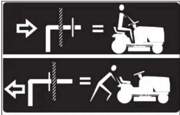
-
Lift the attachment to the highest position with the attachment lift control.
-
Pull the freewheel control out and into the slot and release to hold it in the disengaged position.
-
Do not move the product at more than two (2) mph (3.2 km/h).
-
To reengage transmission, reverse the above procedure.
Tow safety
- Only use tow equipment approved by Husqvarna.
- Use the tow bar to attach the equipment.
- Do not tow equipment that is heavier than the maximum permitted weight.
• Make sure that no other persons is near the product when you tow equipment. - Do not tow equipment on slopes or rough ground.
- Operate the product at low speed when you tow equipment.
Storage
Prepare the product for storage at the end of the season, and before more than 30 days of storage. If you keep fuel in the fuel tank for 30 days or more, tacky particles can cause blockage in the carburetor. This has a negative effect on the engine function.
To prevent tacky particles during storage, add a stabilizer. If alkylate gasoline is used, stabilizer is not necessary. If you use standard gasoline, do not change to alkylate gasoline. This can cause sensitive rubber parts to become hard. Add stabilizer to the fuel in the tank or in the container used for storage. Always use the mixing ratios given by the manufacturer. Run the engine for a minimum of 10 minutes after you add the stabilizer until it flows into the carburetor.

WARNING: Do not keep the product with fuel in the tank in an indoor location or in locations with bad airflow. Risk of fire if fuel fumes come near open flames, sparks, or pilot lights in for example boilers, hot water tanks and clothes dryers.

WARNING: Remove grass, leaves and other flammable materials from the product to decrease the risk of fire. Let
the product become cool before you put it in storage.
- Clean the product, see To clean the product on page 21. Repair paint damages to prevent corrosion.
- Examine the product for worn or damaged parts and tighten loose screws and nuts.
- Remove the battery. Clean it, charge it, and keep it cool during storage.
- Change the engine oil, and discard the waste oil.
- Empty the fuel tank. Start the engine and run it until there is no remaining fuel in the carburetor.
Note: Do not empty the fuel tank and carburetor if a stabilizer has been added.
- Remove the plugs and put about a tablespoon of engine oil into each cylinder. Manually turn the engine shaft to apply the oil and put the plugs back on.
- Lubricate all grease nipples, joints and axles.
- Keep the product in a clean and dry area and cover it for more protection.
- A cover for protection of your product during storage or transport is available at your dealer.
Disposal
• Chemicals can be dangerous and must not be discarded on the ground. Always discard used chemicals at a service center or an applicable disposal location.
- When the product is worn out, send it to the dealer or to an applicable recycling location.
- Oil, oil filters, fuel and the battery can have negative effects on the environment. Obey
the local recycling requirements and applicable regulations.
- Do not discard the battery as domestic waste.
- Send the battery to a Husqvarna service agent or discard it at a disposal location for used batteries.
Technical data
| TS142L | |
| Engine | |
| Engine brand LCC | |
| Engine model LC1P92F | |
| Nominal engine output, kW / hp 1 | 8.9 / 11.9 |
| Max. engine speed, rpm 2600 ± 100 | |
| Engine idle speed, rpm 1750 | |
| Maximum speed forward, mph / km/h 4.2 / 6.7 | |
| Maximum speed reverse, mph / km/h 4.2 / 6.7 | |
| Fuel, minimum octane grade, lead-free, max 10% Ethanol and max 15% MTBE, AKI / RON | 87 / 91 |
| Fuel tank volume, gallons / l 1.5 / 5.67 | |
| Oil type above 32°F / 0°C (API: SJ-SN): SAE 30 | |
| Oil type below 32°F / 0°C (API: SJ-SN): SAE 5W30 | |
| Oil volume with oil filter, gallons / l 0.37 / 1.4 | |
| Oil volume without oil filter, gallons / l 0.34 / 1.3 | |
| Lubrication system Pressure with oil filter | |
| Cooling system Air cooled | |
| Air filter 5907973101 | |
| Alternator, V. amp. @ 3600 rpm 12 V 15 amp @ 3600 rpm | |
| Start motor Electric start 12 V | |
| Weight | |
| Weight, with empty tanks, lb / kg 440 / 200 | |
| Cutting deck | |
| Number of blades | 2 |
| Blade length, in. / cm | 21 / 53 |
| Cutting Width, in. / cm | 42.13 / 107 |
| Cutting Height, in. / cm | 1.5–4.0 / 3.8–10.2 |
| Tires | |
| Tire pressure, rear – front, kPa / PSI / bar | 103 / 15 / 1 |
| Front tires, in. 15 x 6-6 | |
| Rear tires, turf pneumatic, in. | 18 x 9.5-8 |
1 The power rating as declared by the engine manufacturer is the average gross power output at the specified RPM of a typical production engine for the engine model measured using SAE Standards for engine gross power. Refer to the engine manufacturer engine specifications.
| TS142L | |
| Brakes Mechanical parking brake | |
| Electrical system | |
| Type 12 V | |
| Battery 28 A | |
| Spark plug XC12YC | |
| Electrode gap, in. / mm 0.030 / 0.76 | |
| Spark plug torque, lb-ft / Nm 14.75 / 20 | |
| Noise emissions ^2 | |
| Sound power level, measured dB(A) 99 | |
| Sound power level, guaranteed LWA dB(A) 100 | |
| Sound levels ^3 | |
| Sound pressure level at the operators ear, dB(A) 85 | |
| Vibration levels ^4 | |
| Vibration level on the steering wheel, m/s ^2 | 2.78 |
| Vibration level in the seat, m/s ^2 | 0.37 |
Service
Service
Do a yearly check at an authorized service center to make sure that the product functions safely and at its best during high season. The best time to do a servicing or overhaul of the product is low season.
When you send an order for the spare parts, give information about the purchase year, model, type, and serial number.
Always use original spare parts.
Declaration of Conformity
EU declaration of conformity
We, Husqvarna AB, SE 561 82 Huskvarna,
SWEDEN, declare under our sole responsibility that
the represented product:
| Description Combustion-engine-powered ride-on lawn mower with seated operator | |
| Brand | Husqvarna |
| Platform / Type / Model | TS142L |
| Batch Serial number dating and onwards | |
complies fully with the following EU directives and regulations:
| Directive/Regulation Description | |
| 2006/42/EC “relating to machinery” | |
| 2011/65/EU “restriction of use of certain hazardous substances” | |
| 2014/30/EU “relating to electromagnetic compatibility” | |
| 2000/14/EC, 2005/88/EC “relating to outdoor noise” |
Harmonized standards and/or technical
specifications applied are as follows: EN ISO
12100:2010, EN ISO 14982:2009, EN ISO 5395-1
& 3:2013, EN ISO 3744:2010, EN ISO 11094:1991,
EN 1032:2009, EN IEC 63000:2018.
In accordance with directive 2000/14/EC, Annex VIII, the declared sound values are stated in the technical data section of this manual and in the signed EU Declaration of Conformity.
The supplied combustion-engine-powered ride-on lawn mower with seated operator conforms to the example that underwent examination.
On behalf of Husqvarna AB, SE 561 82 Huskvarna, SWEDEN, 2021-06-07
$$ \Delta \cdot 2 m $$
Claes Losdal
Responsible for technical documentation

UK Declaration of conformity
We, Husqvarna AB, SE-561 82 Huskvarna,
Sweden, tel: +46-36-146500, declare on our sole
responsibility that the product:
| Description Combustion-engine-powered ride-on lawn mower with seated operator | |
| Brand | Husqvarna |
| Type / Model | TS142L |
| Identification Serial numbers dating from 2021 and onwards | |
complies fully with the following UK directives and regulations:
| Directive / Regulation Description | |
| S.I. 2008/1597 The Supply of Machinery (Safety) Regulations 2008 | |
| S.I. 2016/1091 The Electromagnetic Compatibility Regulations 2016 | |
| S.I. 2001/1701 The Noise Emission in the Environment by Equipment for use Outdoors Regulations 2001 | |
| S.I. 2012/3032 The restriction of the use of Certain Hazardous Substances in Electrical and Electronic Equipment 2012 | |
Harmonized standards and/or technical
specifications applied are as follows: EN ISO
12100:2010, EN ISO 14982:2009, EN ISO 5395-1
& 3:2013, EN ISO 3744:2010, EN ISO 11094:1991,
EN 1032:2009, EN IEC 63000:2018.
In accordance with directive statutory instrument
S.I. 2001/1701, conformity assessment procedure, schedule 9, the declared sound values are stated in the technical data section of this manual and in the
signed UK Declaration of Conformity.
The supplied combustion-engine-powered ride-on lawn mower with seated operator conforms to the example that underwent examination.
On behalf of Husqvarna AB, SE 561 82 Huskvarna, SWEDEN, 2021-06-07
UK Importer:
Husqvarna UK Ltd
Preston Road, Co. Durham
DL5 6UP

John Thompson
Responsible for technical documentation

Sommaire

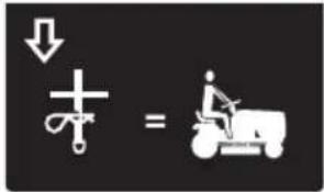


natural_image
Line drawings of two different boots, one showing a side view and the other a front view (no text or symbols)Boulon hexagonal (2)
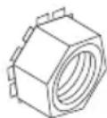
Écrous (2)
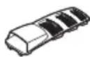
natural_image
Diagram of a car air vent with airflow direction indicated by an arrow (no text or symbols present)natural_image
Diagram of a car air intake manifold with directional arrows indicating flow or movement (no text or symbols)natural_image
Diagram of a hand pressing down on a car's side panel with a handle (no text or symbols)natural_image
Technical line drawing of a car interior showing a hand tool interacting with a gear shift (no text or symbols)
AVERTISSEMENT: les

REMARQUE: placez
natural_image
Technical line drawing of a mechanical assembly with a central hub and mounting bracket (no text or symbols)Reverse Operation System (ROS).

Achteruit.

Vooruit.

Verlichting aan.
Brandstof.

Oliedruk.

Accu.

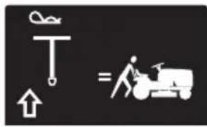

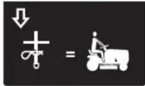
natural_image
Line drawings of two different boots, one open and one closed, shown in side and top views (no text or symbols)natural_image
Diagram of a car air vent system with airflow direction indicated by an arrow (no text or symbols present)natural_image
Diagram of a car air vent with airflow direction indicated by arrows (no text or symbols)natural_image
Diagram of a car interior showing a hand pressing down on the intake tray with a downward arrow (no text or symbols)De stoel afstellen
WAARSCHUWING: Benzine is
WAARSCHUWING: Voordat
natural_image
Technical line drawing of a car interior showing a hand operating a gear shift lever (no text or symbols)WAARSCHUWING: Risico
WAARSCHUWING: Risico
natural_image
Technical line drawing of a mechanical assembly with labeled component A (no text or symbols beyond label)
WAARSCHUWING: De

natural_image
Technical line drawing of a mechanical component with a central hub and mounting bracket (no text or symbols)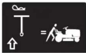
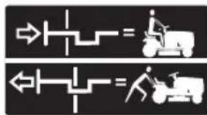
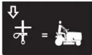
natural_image
Line drawing of a pair of boots with visible tread pattern and buckles (no text or symbols)natural_image
Diagram of a car air vent system with airflow direction indicated by an arrow (no text or symbols present)natural_image
Diagram of a car air intake manifold with airflow direction indicated (no text or symbols)natural_image
Diagram of a hand pressing down on a car intake tray with a downward arrow (no text or symbols)natural_image
Technical line drawing of a car interior showing a hand tool interacting with a gear and intake tray (no text or symbols)

natural_image
Technical line drawing of a mechanical assembly with a pump and wheel (no text or symbols)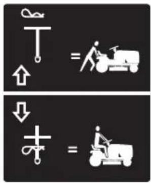
natural_image
Line drawing of a pair of boots with visible branding and sole details (no text or symbols)natural_image
Diagram of a car air vent with mesh insulation and airflow direction arrow (no text or symbols)natural_image
Diagram of a car air vent with airflow direction indicated by arrows (no text or symbols)natural_image
Diagram of a hand pressing down on a car intake tray (no text or symbols)Ajuste del asiento
natural_image
Technical line drawing of a car interior showing a hand operating a gear shift lever (no text or symbols)flowchart
graph TD
    A["Car"] --> B{Curved Lane 1}
    B --> C{Curved Lane 2}
    C --> D{Curved Lane 3}
    D --> E{Curved Lane 4}
    E --> F{Curved Lane 5}
    F --> G{Curved Lane 6}
    G --> H{Curved Lane 7}
    H --> I{Curved Lane 8}
    I --> J{Curved Lane 9}
    J --> K{Curved Lane 10}
    K --> L["Downward Arrow"]
    L --> M["Upward Arrow"]
    M --> N["Upward Arrow"]
    N --> O["Upward Arrow"]
    O --> P["Upward Arrow"]
    P --> Q["Upward Arrow"]
    Q --> R["Upward Arrow"]
    R --> S["Upward Arrow"]
    S --> T["Upward Arrow"]
    T --> U["Upward Arrow"]

ADVERTENCIA: Las

natural_image
Technical line drawing of a mechanical component with a clamping wheel and mounting bracket (no text or symbols)
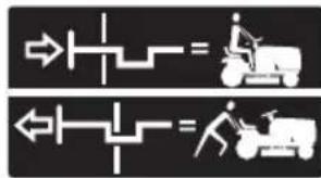
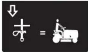
natural_image
Line drawings of two types of boots, one side view and one front view, with no text or symbols present.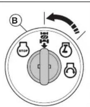
Lenkradadapter, 1 Stk

natural_image
Diagram of a car air vent system with airflow direction indicated by an arrow (no text or symbols present)natural_image
Diagram of a car intake tray with a downward arrow indicating flow or movement (no text or symbols)natural_image
Diagram of a car interior showing hand pressing down on a tray with a downward arrow (no text or symbols)natural_image
Technical line drawing of a car interior showing a hand tool interacting with the intake tray (no text or symbols)

natural_image
Technical line drawing of a mechanical assembly with a central hub and mounting bracket (no text or symbols)- Fold this page along dotted line indicated above.
- Hold page before you so that its left edge is vertically parallel to a tree trunk or other upright structure.
- Sight across the fold in the direction of hill slope you want to measure.
- Compare the angle of the fold with the slope of the hill.
Husqvarna®
www.husqvarna.com
Original instructions