Windwaker Eco - Air Conditioning Klarstein - Free user manual and instructions
Find the device manual for free Windwaker Eco Klarstein in PDF.

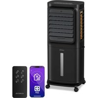
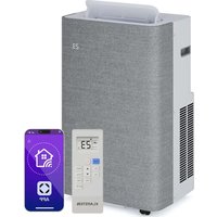
| Technical Features | Klarstein Windwaker Eco portable air conditioner, cooling capacity of 7000 BTU, energy class A. |
|---|---|
| Operating Modes | Cooling function, dehumidification, ventilation. |
| Noise Level | 35 dB(A) in silent mode. |
| Dimensions | Compact dimensions for easy transport: 30 x 30 x 70 cm. |
| Weight | Approximately 25 kg. |
| Energy Consumption | Electric consumption of 800 W. |
| Usage | Easy to install, remote control included for remote operation. |
| Maintenance | Washable filters, regular cleaning recommended for optimal operation. |
| Safety | Overheat protection, automatic shutdown when the tank is full. |
| General Information | Ideal for rooms up to 20 m², modern and elegant design. |
Frequently Asked Questions - Windwaker Eco Klarstein
User questions about Windwaker Eco Klarstein
0 question about this device. Answer the ones you know or ask your own.
Ask a new question about this device
Download the instructions for your Air Conditioning in PDF format for free! Find your manual Windwaker Eco - Klarstein and take your electronic device back in hand. On this page are published all the documents necessary for the use of your device. Windwaker Eco by Klarstein.
USER MANUAL Windwaker Eco Klarstein
ONNNNNNNNNNNNNNNNNNNNNNNNNNNNNNNNNNNNNNNNNNNNNNNNNNNNNNNNNNNNNNNNNNNNNNNNNNNNNNNNNNNNNNNNNNNNNNNNNNNNNNNNNNNNNNNNNNNNNNNNNNNN
KLARSTEIN
www.klarstein.com

Member of Berlin Brands Group
Handwerkerstr. 11
15366 Dahlwitz-Hoppegarten
Deutschland
Berlin Brands Group UK Ltd
PO Box 1145
Oxford,OX19UW
United Kingdom
Dear Customer,
Congratulations on purchasing this equipment. Please read this manual carefully and take care of the following hints to avoid damages. Any failure caused by ignoring the items and cautions mentioned in the instruction manual is not covered by our warranty and any liability. Scan the QR code to get access to the latest user manual and other information about the product.

CONTENT
Notes on Refrigerant R32 64
Safety Instructions 65
Quick Start 68
Device Overview 68
Remote Control 69
Start-Up and Operation 70
Additional Functions and Key Combinations 80
Emergency Button 81
Installation of the Indoor Unit 82
Installation of the Outdoor Unit 96
Test Operation 107
Configuration of the Connection Pipe 107
Cleaning and Maintenance 112
Troubleshooting 116
Disposal Considerations 120
Manufacturer & Importer (UK) 120
TECHNICAL DATA
| Item number 10033600, 10033601, 10033602, 10033603 |
| Power supply 220-240 V ~ 50/60 Hz |
| Application (outdoor unit) -22 °C to 43 °C |
| Adjustable temperature 16 °C to 30 °C (61 °F to 86 °F); |
NOTES ON REFRIGERANT R32
Warnings
- The air conditioning system must be kept and transported upright. Otherwise, irreparable compressor damage may occur. Leave the unit for at least 24 hours before putting it into operation.
- Switch off the device and disconnect it from the power supply before cleaning.
- Make sure that the product creates a steady stream of air. Ensure the air inlets and outlets are not blocked.
- To prevent leaks, operate this unit on a horizontal surface.
- Any person performing work on a refrigerant circuit should have a current certificate from an industry-accredited assessment body. This ensures competence for the safe handling of refrigerants according to an industry-recognised assessment specification.
- If the device stops working, dispose of it properly.
- Store the device in a well-ventilated place when not in use.
- Store the device so that it is not damaged.
- Repairs may only be carried out by the manufacturer or an authorised specialist company.
- The cables connected to the device may contain potential ignition sources.
- Do not damage any components of the refrigerant circuit. Escaping refrigerant may not be noticed because it is odourless.
- Maintenance and repairs must be carried out under the supervision of specialists in the use of flammable refrigerants.
Information for rooms with refrigerant pipes
- Limit the piping to a minimum.
- Be careful not to damage the piping.
- Appliances with flammable refrigerants may only be installed in a well-ventilated room.
- Comply with national gas regulations.
- All mechanical connections must be freely accessible for maintenance purposes.
CAUTION
Risk of fire! This device contains the flammable refrigerant R32. If the refrigerant escapes and is exposed to an external ignition source, there is a risk of fire.
SAFETY INSTRUCTIONS
General instructions
- This device may be used by children over the age of 8 and by persons with limited physical, sensory and mental abilities and/or lack of experience and knowledge if they have been instructed in the device, are able to operate it safely and understand the dangers involved.
The device is not a toy. - Only allow children to clean and maintain the appliance under supervision.
- Do not connect the appliance to a power outlet as this may result in a fire hazard.
- Before cleaning the appliance, unplug the appliance from the wall outlet to avoid the risk of electric shock.
- If the power cord is damaged, it must be replaced by the manufacturer, customer service or a similarly qualified person to avoid hazards.
- Do not wash the product with water, as this may result in electric shock.
- Never spray water into the indoor air conditioner. This could result in an electric shock or malfunction of the unit.
After removing the filter, do not touch the blades of the unit as this may cause injury. - Do not use fire or a hairdryer to dry the filter after cleaning as this may deform the filter or cause a fire.
- Maintenance must be carried out by qualified personnel, otherwise property damage and/or personal injury may result.
- Do not attempt to repair the product yourself as this may result in electric shock or damage to the product. Contact your service representative if the unit needs service.
- Do not insert your fingers or other foreign objects into the air inlets and outlets as this may cause damage to property and/or personal injury.
- Do not block the air inlets and outlets as this may cause malfunction.
- Do not spill water on the remote control as this may damage it.
- Using the air conditioner in unusual conditions may cause malfunction, electric shock, or fire.
-
If you turn the unit on or off by pressing the emergency button, press it with a well insulated object and never with a metallic object.
-
Do not stand on the top cover of the unit or place heavy objects on it as this may result in property damage and/or personal injury.
- Installation must be performed by qualified personnel. Failure to do so may result in property damage and/or personal injury.
- Electrical safety regulations must be observed when installing the equipment.
- Ensure that power supply switches and circuit breakers are installed and used in accordance with local safety regulations.
- Install a circuit breaker. Failure to install an isolating switch may result in malfunction of the equipment.
- An all-pole circuit breaker should be installed in the fixed wiring with a distance of at least 3mm between the poles.
- The unit should be fully grounded. Insufficient grounding may result in electric shock.
- Use only the power cord recommended by the manufacturer.
- Ensure that the power supply meets the requirements of the equipment. Inadequate power supply or incorrect wiring may cause the unit to malfunction. Install the correct power lines and cables before using the product.
- Connect the live wire, neutral wire, and ground wire correctly.
- Make sure to unplug the appliance from the power supply before performing any electrical work.
- Do not plug the power plug into the wall outlet until the installation is complete.
- If the power cord is damaged, it must be replaced by the manufacturer, customer service or a similarly qualified person to avoid hazards.
- The temperature of the refrigerant circuit will be high. Keep the connecting cable away from the copper lines.
- The unit must be installed in accordance with national wiring regulations.
- The air conditioner is a high quality electrical appliance. It must be grounded by a qualified person using a special grounding device. Always make sure that the grounding is done correctly, otherwise there is a risk of electric shock.
- The yellow-green cable of the air conditioner is the earthing cable which must not be used for other purposes.
- The grounding resistance should comply with national electrical safety regulations.
- The unit must be installed so that the mains plug is easily accessible.
-
All cables and lines of the equipment should be connected by a qualified person.
-
If the length of the power cable is insufficient, contact customer service to obtain a longer cable. Do not attempt to extend the cable yourself.
- For air conditioning systems without a mains plug, an isolating switch must be installed in the cable.
- If you wish to use the air conditioner in a different location, have the disassembly and new installation carried out by a qualified person. Otherwise, property damage and/or personal injury could result.
- Select an installation location that is out of the reach of children and at a safe distance from plants and animals. If this is not possible, you should erect a fence for safety reasons.
- The indoor air conditioner should be installed close to the wall.
- Installation instructions for this unit are provided by the manufacturer.
Special instructions
- Only use methods recommended by the manufacturer to speed up the defrosting process or carry out cleaning.
- If repairs are required, contact customer service. Repairs carried out by unqualified personnel can be dangerous.
- The unit should be stored in a room that is not permanently exposed to potential sources of ignition, such as naked flames, a powered gas appliance, or an electric heater.
- Do not puncture or burn the appliance.
- The appliance has been filled with the flammable gas R32.
- Follow the operating instructions exactly when carrying out repairs.
- Be aware that the refrigerant is odorless. Read the relevant operating instructions for the refrigerant.
-
If any of the phenomena listed below should occur, turn off the air conditioner and immediately unplug the power cord from the wall outlet and contact Customer Service or a similarly qualified person for repair and maintenance:
-
The power cord is overheated or damaged,
- The circuit breaker is regularly activated,
- The air conditioner emits the smell of combustion,
- There's a leak in the air conditioner.
CAUTION
Risk of injury! Do not repair or service the air conditioner yourself. Using the air conditioner in abnormal conditions may result in malfunction, electric shock or fire.
QUICK START
1 After plugging the indoor air conditioner power plug into the wall outlet, press the POWER button on the remote control to turn on the indoor air conditioner.
2 Press the MODE button to set the desired mode: AUTO, COOL, DRY, FAN, HEAT.
3 Press the ARROW KEYS to set the desired temperature (the temperature cannot be adjusted in automatic mode).
4 Press the FAN key to set the fan speed: auto > low > low-medium > medium > medium-high > high.
5 Press the SWING buttons to set the air discharge angle.
DEVICE OVERVIEW
Indoor Unit
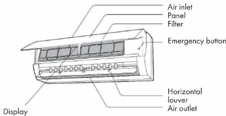
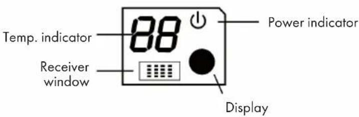
Note: Actual product may be different from above graphics, please refer to actual products.
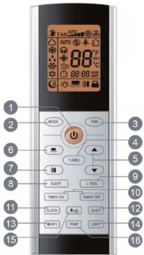
Key Functions
| 1 | POWER (On/Off) | 9 | I FEEL (room temperature detection) |
| 2 | MODE | 10 | TIMER ON/OFF |
| 3 | FAN (fan) | 11 | CLOCK |
| 4 | TURBO | 12 | QUIET |
| 5 | ARROW KEYS | 13 | WIFI |
| 6 | SWING right/left | 14 | LIGHT |
| 7 | SWING up/down | 15 | Health/cleaning function |
| 8 | SLEEP | 16 | TEMP (temperature setting) |
Display Indicators and Symbols
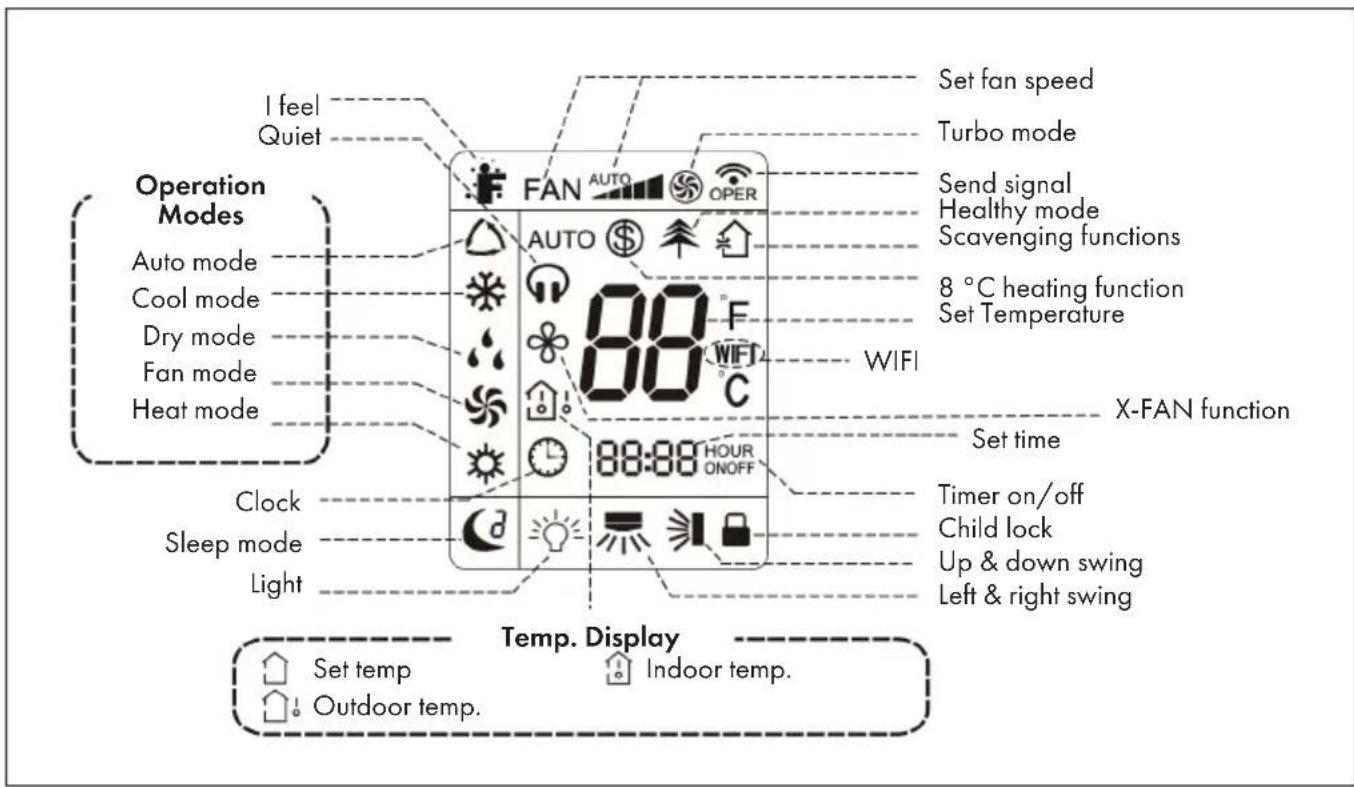
Note: This is a general representation of the unit. Some models have this feature while others do not. Refer to your actual model.
START-UP AND OPERATION
Important Notes on Operation
- It is a general remote control that can be used for air conditioners of all models. If you press a button on the remote control whose function your air conditioner does not have, the air conditioner continues to operate in the currently set mode.
- After the air conditioner is switched on, a signal sounds. The power indicator lights up (red, colour may vary between models). After switching on, you can operate the air conditioner with the remote control.
-
If you press a button on the remote control when it is switched on, the WLAN symbol on the remote control screen flashes briefly once and the air conditioner emits a "di" sound, meaning that the signal from the remote control has been received.
-
As for the models with functions of WiFi or wired controller, the indoor unit must has been controlled by standard remote controller under auto mode first, and then the function of adjustable temperature under auto mode can be realized by APP or the wired controller.
- This remote controller can adjust the temperature under auto mode. When matching with the unit which is without the function of adjustable temperature under auto mode, the set temperature under auto mode may be invalid, or the displayed set temperature on the unit is not same as that on the remote controller under auto mode.
POWER - Switching the device on and off
- Press the POWER button to turn on the unit.
- Pressing this button again turns off the power.
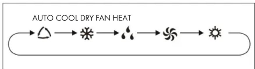
MODE - Modus
Press the MODE button repeatedly to select the desired operating mode:
- If you have selected the automatic mode, the device runs according to the measured temperature. You can adjust the fan speed by pressing the FAN key. You can adjust the swing angle by pressing one of the two SWING buttons. In automatic mode, the temperature can be displayed; in automatic mode, the set temperature can be adjusted.
-
If you select the cooling mode, the unit will run in the cooling mode accordingly. The cooling icon is displayed on the unit (for some models, this may not be available). Press the ARROW KEYS to adjust the temperature. You can adjust the swing angle by pressing one of the two SWING buttons.
If you select the dry mode, the air conditioner runs at low speed in the dry mode. The dry indicator on the indoor air conditioner screen is on (for some models this indicator may not be available). The fan speed cannot be adjusted in dry mode. You can adjust the swing angle by pressing either of the two SWING buttons or -
When you select the fan mode, only the fan is turned on and the unit does not cool or heat additionally. All indicator lights, except the power indicator, are off. You can adjust the fan speed by pressing the FAN key. By pressing one of the two SWING buttons, you can adjust the swing angle.
- If you select the heating mode, the air conditioner runs in the heating mode. The display appears on the indoor air conditioner screen (for some models, this display may not be available). Use the ARROW KEYS to adjust the speed. Press the FAN button to adjust the fan speed. You can adjust the swing angle by pressing one of the two SWING buttons. An air conditioner that only has the cooling function does not receive the heating signal. If you set the heating mode, the appliance cannot be switched on by pressing the POWER button.
Note: To prevent cold air from being blown out after the heating mode is started, the unit will not blow any air for the first 1-5 minutes (this time depends on the indoor ambient temperature).
FAN - Adjust Fan Speed
Press FAN repeatedly to select the speed you want: auto > low > low-medium > medium > medium-high > high.

- In dry mode, only the low speed is available.
- X-FAN Function: If you press and hold the FAN button for two seconds in Cool or Dry mode, the icon appears on the screen. The unit will then continue to operate for a few minutes to dry the indoor air conditioner, even if you have already turned it off. After drying, the function is automatically deactivated. This function is not available in automatic, fan and heating mode. This function allows liquid that has accumulated in the appliance after it has been switched off to be blown out in the form of steam, thus preventing mould.
- Activated X-FAN function: After switching off the appliance by pressing the On/Off button, the appliance continues to run at low speed for a few minutes. If you want to turn off the unit completely at this time, press and hold the FAN button for 2 seconds.
- Deactivated X-FAN function: After the unit is turned off by pressing the On/Off key, the unit stops immediately and is completely off.
TURBO - Turbo Function
- If you press this button in cooling or heating mode, the unit will cool or heat to the maximum. The Turbo icon will be displayed on the remote control. Press this button again to exit the turbo function. The turbo icon will disappear from the screen.
- When you start this function, the fan will run at the highest speed so that the ambient temperature reaches the temperature set on the unit as quickly as possible.
Arrow Keys
Press the ARROW KEYS to increase or decrease the set temperature by 1^(^ F) . If you press and hold the buttons for more than 2 seconds, the temperature displayed on the remote control will change rapidly. Release the button when the desired temperature is set. The indoor air conditioner adjusts its temperature display accordingly.
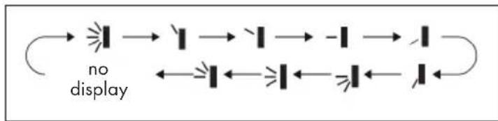
Swing Function left/right
If you press this button, you can select the swing angle (left/right). By pressing this key several times, the swing angle is adjusted as follows:
- If you keep this button pressed for longer than 2 seconds, the unit swings from left to right and back. As soon as you release the button, the unit stops swinging from left to right and the current position of the guide grid is maintained.
- If you activate the swing mode and press the button again two seconds later, the swing mode will stop immediately. If you press the button again within 2 seconds, the pan status will change depending on the sequence shown above.
Note: This function is only available for some models.
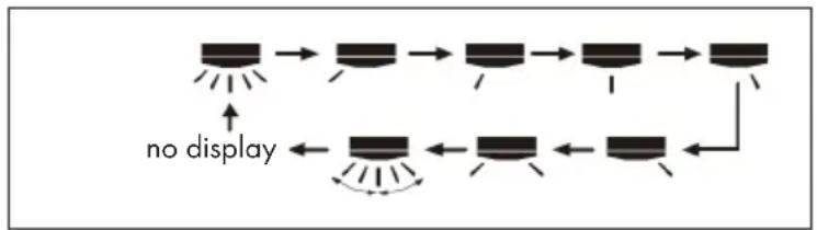
Swing Function up/down
If you press this button, you can select the swivel angle (up/down). By pressing this key several times, the swivel angle is adjusted as follows:
-
When you select the first stage, the air conditioner automatically blows the air out. The horizontal ventilation opening swings up and down at the maximum angle.
-
When you select the next 5 levels, the air conditioner blows the air in a fixed position. The horizontal ventilation opening automatically stops at this position.
-
When you select the last 3 steps, the air conditioner blows the air at a fixed angle. The horizontal ventilation opening blows the air out at the specified angle.
-
Press and hold the button for 2 seconds to set the desired swivel angle. Release the button as soon as the angle is reached.
-
The last 3 steps may not be available. If this is the case, the air conditioner will automatically blow out the air when it receives the signal.
-
If you keep this button pressed for more than 2 seconds, the unit will swing from top to bottom. As soon as you release the button, the unit stops swinging and the position of the horizontal ventilation opening is maintained.
-
If you activate the swivel mode and press the button again two seconds later, the swivel mode will stop immediately. If you press the button again within 2 seconds, the pan status will change depending on the sequence shown above.
SLEEP (Sleep Mode)
When you press this button, you can select Sleep1(), Sleep2(), Sleep3() and Sleep OFF. Press this button several times to select the desired profile.

Sleep1: In cooling mode, when sleep function 1 is activated, the temperature of the air conditioner is increased by 1^ after one hour running time. After two hours of operation, the temperature is increased by a further 2^ . The unit then continues to run permanently at this temperature. In cooling mode, when sleep function 1 is activated, the set temperature is reduced by 1^ after one hour running time. After two hours of operation, the set temperature is lowered by a further 2^ . The device then continues operation with this temperature setting.
Sleep2: In this mode, the unit runs according to the default setting of a group of sleep temperature curves.
Sleep3: In this mode, all settings can be made by the user.
1 At this time, the remote control time display shows [1 HOUR] and the corresponding temperature of the last set sleep curve is displayed on the screen and flashes (the first time the unit is used, the factory preset initial value of the sleep curve setting is displayed).
2 Adjust the temperature by pressing the ARROW buttons and confirm your selection by pressing the TURBO button.
3 At this time, the time position of the remote control is automatically increased by one hour (this means: 2 HOUR, 3 HOUR, ...to 8 HOUR), the temperature display shows the corresponding temperature of the last set sleep curve and flashes.
4 Repeat steps 2 and 3 until the temperature setting has been made for the entire 8 hours and the sleep curve setting has been completed. The remote control display will then return to the original settings.
If you want to use an individualised setting for the sleep curve setting but do not want to change the temperature, press the TURBO button to continue switching.
Note: If no button is pressed within 10 seconds, the sleep curve setting is automatically cancelled and the original settings are displayed. If you wish to cancel the sleep curve setting, you can do so by pressing one of the POWER, MODE, TIMER and SLEEP buttons.
IFEEL - Room Temperature Detection
When you press this button, this function is started and displayed on the remote control screen. After activating this function, the remote control sends the measured ambient temperature to the unit. The air conditioner will then adjust the temperature accordingly. If you press this button again, the function is terminated and the symbol disappears from the remote control screen.
- When using this function, place the remote control near you and be careful not to place the remote control near objects with high or low temperatures as this may cause incorrect ambient temperature values to be measured.
- When this function is active, the remote control should be near the air conditioner so that it can receive the signal sent by the remote control.
TIMER - Setting the Timer
Set the power-on timer:
Press TIMER ON to set the air conditioning on time. When you press the button, the clock icon on the screen disappears and the word [ON] blinks on the remote control. Press the ARROW buttons to adjust the setting. Each press increases or decreases the setting by one minute. Pressing and holding these buttons changes the set time more quickly. Release the corresponding button once you have reached the desired time setting. Press the Timer on button to confirm your setting. The word [ON] will stop blinking and the timer icon will be displayed again.
Note: To cancel this function, press the TIMER ON button again.
Set Off Timer:
Press TIMER OFF to set the air conditioner off time. When you press the button, the clock icon on the screen disappears and the word [OFF] blinks on the remote control. Press the ARROW buttons to adjust the setting. Each press increases or decreases the setting by one minute. Pressing and holding these buttons changes the set time more quickly. Release the corresponding button once you have reached the desired time setting. Press the TIMER ON button to confirm your setting. The word [OFF] will stop blinking and the timer icon will be displayed again.
- The two functions Timer on and Timer off can be activated simultaneously.
- Set the current time on the unit before activating the timer.
- Set valid values after activating the respective timer function. The POWER button does not affect the setting. If you do not need this function, deactivate it with the remote control.
CLOCK - Setting the Time
- Press the CLOCK button to set the time. The clock icon links on the remote control.
- Within 5 seconds, press the ARROW KEYS to adjust the time. Pressing the respective button will either add one minute to the time or subtract one minute.
- If you press and hold the ARROW KEYS, the number of minutes changes faster. Release the button once the desired time has been set.
- Press the CLOCK button to confirm your setting. The clock symbol will stop flashing.
Note: The time is displayed in 24-hour format. The time between two entries must not exceed 5 seconds, otherwise the setting mode will be cancelled. See point 10 for activating the timer.
QUIET - Quiet Mode
When the QUIET button is pressed, the auto silent mode is activated (the icons and AUTO are displayed on the screen), when the button is pressed again, the normal silent mode is activated (only the headphone icon is displayed on the screen), and when the button is pressed three times, the silent mode is deactivated (the headphone icon is not displayed on the screen). When turned on, the silent mode is the default setting.
- The silent mode can be set in all modes. Fan speed adjustment is not possible in this mode.
- If the silent mode is selected, this has the following effect on the different modes:
- The indoor air conditioner runs at speed level 4. Ten minutes later, or when the indoor temperature is ≤ 28^ , the unit continues to run either at speed level 2 or in silent mode, depending on the difference between the ambient temperature and the set temperature.
-
In heating mode, the air conditioner continues to run at either speed 3 or quiet mode, depending on the difference between the ambient temperature and the set temperature.
-
In dry mode, the unit automatically runs in silent mode.
- In automatic mode, the unit runs in automatic silent mode according to the actual cooling, heating or fan mode.
This function is only available on some models.
WIFI Function
Press the WIFI key to activate or deactivate the WIFI function. When WIFI is enabled, the remote control screen displays WIFI. When the remote control is off, press the MODE and WIFI buttons simultaneously for one second to reset this function to the factory settings.
Note: This function is only available on some models.
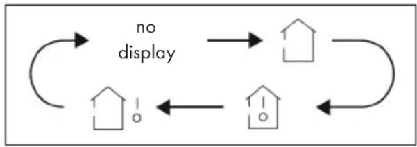
LIGHT - Turn light on/off
Press the LIGHT button to turn off the on-screen illumination of the indoor air conditioner. The light bulb icon no longer appears on the remote control screen. If you press the LIGHT button again, the unit's backlight will turn on again and the bulb icon will appear on the remote control screen.
Health Mode and Cleaning Functions
- Press this button to activate and deactivate the health and cleaning functions of the device in the operating status. Pressing this button once starts the cleaning function and the remote control screen displays
- If you press this button again, the health and cleaning functions will run simultaneously. The remote control screen displays and
- If you press the button a third time, both functions will be cancelled.
- If you press the button a fourth time, the health function will start and the remote control screen will display
- If you press the button again, the unit returns to step 1.
Note: This function is only available on some models.
TEMP - Set Temperature
If you press the TEMP button, you can see the set desired temperature and the actual indoor or outdoor temperature on the air conditioner screen. The remote control setting can be selected in the following order:
| If you select this setting, the temperature display of the indoor air conditioner shows the set temperature. |
| If you select this setting, the indoor air conditioner temperature display will show the actual room temperature. |
| If you select this setting, the indoor air conditioner temperature display will show the outdoor temperature. |
- The outdoor temperature indicator is not available on some models. In this case, if the indoor air conditioner receives the signal to display the outdoor temperature, the indoor temperature is still displayed.
- The indoor air conditioner is factory set to display the set temperature when turned on. There is no separate display option on the remote control for this.
- If you display the indoor or outdoor temperature on the screen of the indoor air conditioner, the unit automatically returns to the set temperature display after 3-5 seconds.
ADDITIONAL FUNCTIONS AND KEY COMBINATIONS
Power Saving Function
In cooling mode, press the TEMP and CLOCK buttons simultaneously to turn the power save function on or off. Once the power save function has been started, [SE] will be displayed on the remote control and the indoor air conditioner will automatically adjust the set temperature to the factory setting for the best energy saving effect. Press the TEMP and CLOCK buttons simultaneously again to exit the power save function.
- In energy saving mode, the fan speed is set automatically and cannot be adjusted.
- In power save mode, the set temperature cannot be changed. If you press the TURBO button in this mode, the remote control will not transmit the signal.
- Sleep function and energy saving function cannot be activated at the same time. If you have activated the power save function in cooling mode, it is deactivated again by pressing the SLEEP button. If the sleep function has been activated in the cooling mode and the power save mode is started, the sleep function is deactivated.
Heating Function
In heating mode, press the TEMP and CLOCK buttons simultaneously to switch the 8^ heating function on or off. Once this function is started, the remote control will display
and [8^] and the air conditioner will maintain the heating status at 8^ so that the room temperature cannot fall below 8^ . The heating status will then be displayed on the remote control. To exit the 8^ heating function, press the TEMP and CLOCK buttons simultaneously again.
- If the 8^ heating function has been activated, the fan speed is set automatically and cannot be adjusted.
- If the 8^ heating function has been activated, the set temperature cannot be changed. If you press the TURBO button in this mode, the remote control will not transmit the signal.
- The 8^ heating function and the sleep function cannot be activated at the same time. If you have activated the 8^ heating function in cooling mode, it is deactivated again by pressing the SLEEP button. If the sleep function has been activated in cooling mode and the 8^ heating function is started, the sleep function is deactivated.
- The 8^ C heating function is displayed as 46^ F heating function in the Fahrenheit setting.
Child Safety Lock
Press both ARROW KEYS simultaneously to turn the parental control on or off. Once the parental control is turned on, the icon will be displayed on the remote control. If you now wish to use the remote control, it will not send a signal to the air conditioner and the lock icon will flash three times.
Switching between Celsius and Fahrenheit
While the unit is turned off, press the and MODE buttons simultaneously to change from ^ C to ^ F or vice versa.
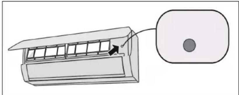
EMERGENCY BUTTON
If the remote control is lost or damaged, use the emergency button to turn the air conditioner on or off. Operating Instructions: As shown in the illustration, open the cover and press the emergency button to turn the air conditioner on or off. When the air conditioner is on, it runs in automatic mode.
WARNING
Risk of injury due to electric shock. Press the button with a well insulated object!
INSTALLATION OF THE INDOOR UNIT
Important installation instructions

WARNING
Risk of injury! All persons involved in the installation of the air conditioning system MUST have the valid certificate of the responsible authority and the qualification recognised by this industry for handling the refrigeration system.
- If other technicians are required for the maintenance and repair of the unit, they should be supervised by the person who has the qualification for the use of the combustible refrigerant.
- The air-conditioning system must only be repaired in accordance with the procedure laid down by the manufacturer of the appliance.
- The air conditioner must not be operated in rooms with open flame devices (such as fi replaces, running coal-gas appliances, running heaters, etc.).
- It is not permitted to drill into or expose the connecting pipe to fire.
- The air conditioner must be installed in a room larger than the specified minimum room size. The minimum room size is indicated on the nameplate or in the following table a.
- A leak test must be carried out after installation of the unit.
Minimum room size (^2)
- When installing or relocating the unit, be sure to keep the refrigerant circuit free from air or substances other than the specified refrigerant. Any presence of air or other foreign substance in the refrigerant circuit will cause system pressure rise or compressor rupture, resulting in injury.
- When installing or moving this unit, do not charge the refrigerant which is not comply with that on the nameplate or unqualified refrigerant. Otherwise, it may cause abnormal operation, wrong action, mechanical malfunction or even series safety accident.
- When refrigerant needs to be recovered during relocating or repairing the unit, be sure that the unit is running in cooling mode. Then, fully close the valve at high pressure side (liquid valve). About 30-40 seconds later, fully close the valve at low pressure side (gas valve), immediately stop the unit and disconnect power. Please note that the time for refrigerant recovery should not exceed 1 minute. If refrigerant recovery takes too much time, air may be sucked in and cause pressure rise or compressor rupture, resulting in injury.
- During refrigerant recovery, make sure that liquid valve and gas valve are fully closed and power is disconnected before detaching the connection pipe. If compressor starts running when stop valve is open and connection pipe is not yet connected, air will be sucked in and cause pressure rise or compressor rupture, resulting in injury.
- When installing the unit, make sure that connection pipe is securely connected before the compressor starts running. If compressor starts running when stop valve is open and connection pipe is not yet connected, air will be sucked in and cause pressure rise or compressor rupture, resulting in injury.
- Prohibit installing the unit at the place where there may be leaked corrosive gas or flammable gas. If there leaked gas around the unit, it may cause explosion and other accidents.
-
Do not use extension cords for electrical connections. If the electric wire is not long enough, please contact a local service center authorized and ask for a proper electric wire. Poor connections may lead to electric shock or fire.
-
Use the specified types of wires for electrical connections between the indoor and outdoor units. Firmly clamp the wires so that their terminals receive no external stresses. Electric wires with insufficient capacity, wrong wire connections and insecure wire terminals may cause electric shock or fire.
Tools required for Installation
| 1 Spirit level 8 Pipe cutter | |
| 2 Screwdrivers 9 Leakage detector | |
| 3 Impact drill 10 Vacuum pump | |
| 4 Drilling head 11 Pressure meter | |
| 5 Pipe expander 12 Universal meter | |
| 6 Torque wrench 13 Inner hexagon spanner | |
| 7 Open-end wrench 14 Measuring tape |
Notes on the Installation Environment
- There must be no blockages or obstacles near the air intake.
- Select a place where the condensation can be easily distributed without adversely affecting other people.
- Select a location where the connection to the outdoor air conditioner can easily be established and which is close to an electrical outlet.
- Select a location that is out of the reach of children.
- The installation site should be able to support the weight of the indoor air conditioner and should not increase the noise level and vibration of the unit.
The unit must be installed at least 2.5 meters above the floor. - Do not install the indoor air conditioner directly above electrical equipment.
- Try to install the indoor air conditioner as far away from fluorescent lamps as possible.
Installing the unit in the following locations may result in malfunction of the unit. The following locations are not suitable for installation. If installation in any of these locations cannot be avoided, contact customer service before installation:
- Locations with strong sources of heat, vapors, flammable or explosive gases, or volatile objects dispersed in the air.
- Places where high frequency equipment is used (such as welding machines, medical equipment, etc.).
- Places near the coast.
- Places where there are oils or vapours in the air.
- Places where sulphurous gases escape or are present.
- Places with similar conditions to those mentioned above.
- The unit must not be installed in washrooms.
- The unit must not be installed on unstable or moving structures (such as a truck) or in corrosive environments (such as a chemical plant).
Step 1: Determining the Location
Recommend an installation location to the customer and then coordinate the exact installation location with the customer.
Step 2: Installing the Wall Suspension
1 Hang the wall suspension from the wall and adjust it with the spirit level in the horizontal position. Mark the screw mounting holes on the wall.
2 Drill the screw fixing holes with a percussion drill (the drill head should have the same properties as the dowels) and then insert the dowels into the holes.
3 Fix the wall suspension with the tapping screws (ST 4.2 × 25 TA) and then pull on the wall suspension to ensure that it is tight and properly installed. If a dowel is loose, drill another hole nearby.
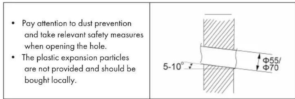
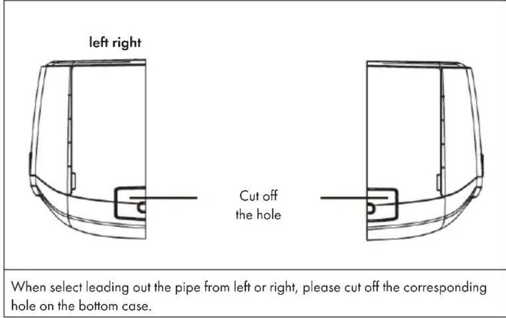
Step 3: Open Piping Hole
1 Choose the position of piping hole according to the direction of outlet pipe. The position of piping hole should be a little lower than the wall-mounted frame, shown as below.
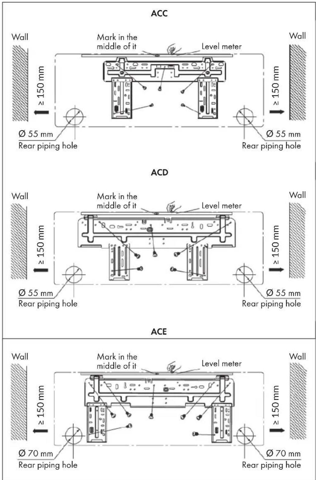
2 Drill a 55 or 70 pipe opening at the selected position of the outlet pipe. To allow the water to drain properly, the pipe opening on the wall should face slightly downwards towards the outside at an angle of 5 - 10^ .
Step 4: Alignment of the Outlet Pipe
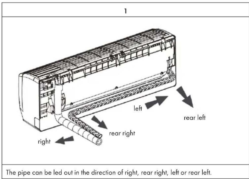
2
Step 5: Connect the Pipe of the Indoor Unit
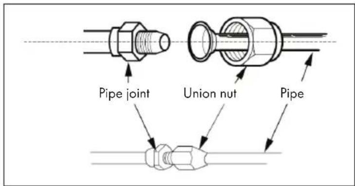
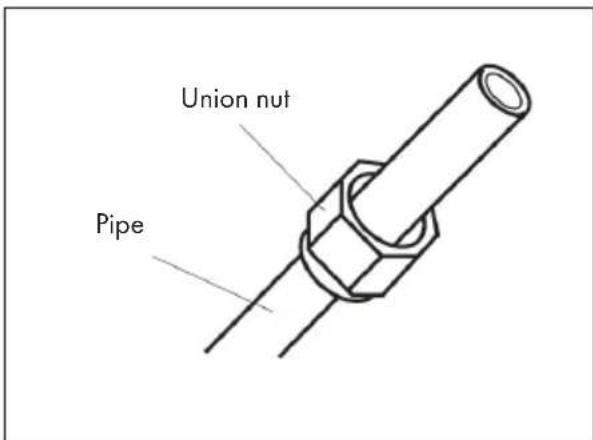
1 Aim the pipe joint at the corresponding bellmouth.
2 Pretighten the union nut with hand.
3 Adjust the torque force by referring to the following sheet. Place the open-end wrench on the pipe joint and place the torque wrench on the union nut. Tighten the union nut with torque wrench.
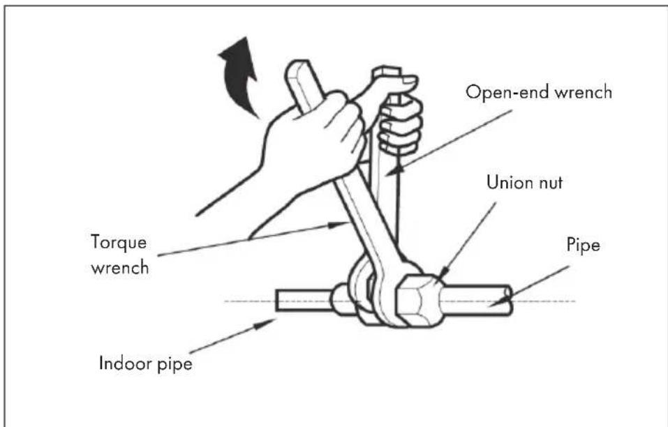
| Hex nut diameter Tightening torque |
| Ø 6 15 - 20 Nm |
| Ø 9,52 30 - 40 Nm |
| Ø 12 45 - 55 Nm |
| Ø 16 60 - 65 Nm |
| Ø 19 70 - 75 Nm |
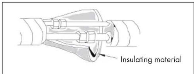
4 Wrap the indoor air conditioner duct and connector with the insulation material and then wrap tape around it.
Step 6: Install Drain Hose
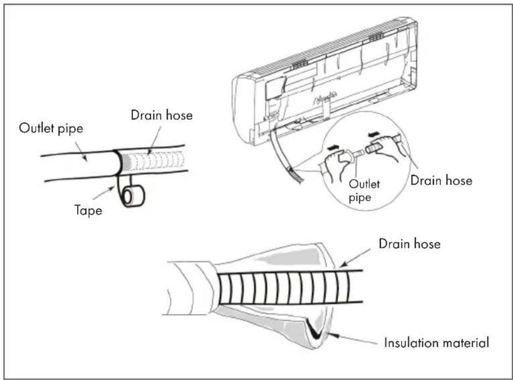
1 Connect the drain hose to the drain line of the indoor air conditioner.
2 Wrap adhesive tape around the connecting piece.
Note: Wrap insulating material around the drain hose to prevent condensation. The plastic plugs are not included.
Step 7: Cable Connection of the Indoor Air Conditioner
1 Open the panel, remove the screw on the wiring cover and then take down the cover.

2 Make the power connection wire go through the cable-cross hole at the back of indoor unit and then pull it out from the front side.
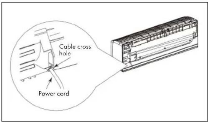
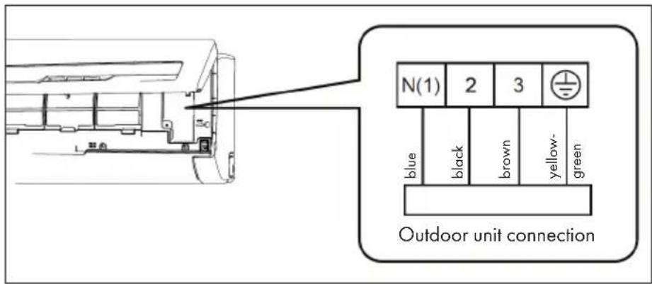
- Remove the wire clip and connect the power connection wire to the wiring terminal according to the color. Tighten the screw and then fix the power connection wire with wire clip. Note: the wiring board is for reference only, please refer to the actual one.
4 Put wiring cover back and then tighten the screw.
5 Close the panel.
Important Notes on Cabling
- All indoor and outdoor air conditioning cables should be connected by a specially qualified person.
- If the length of the mains cable is insufficient, contact Customer Service to obtain a new cable. Avoid extending the cable yourself.
For air conditioners with a mains plug, the mains plug should still be easily accessible after installation. - For air conditioners without a mains plug, a ventilation switch must be installed in the wiring. The ventilation switch should have an all-pole separation and the distance between the individual contacts should be greater than 3mm .
Step 8: Bind up the Pipes
1 Bind up the connection pipe, power cord and drain hose with the band.
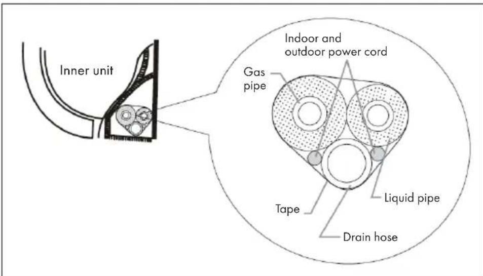
2 Reserve a certain length of drain hose and power cord for installation when binding them. When binding to a certain degree, separate the indoor power and then separate the drain hose.
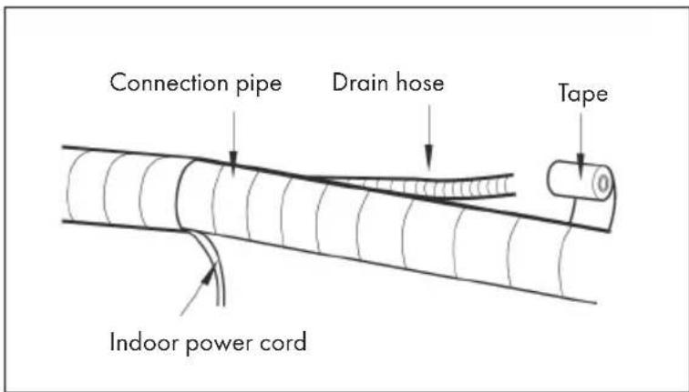
3 Bind them evenly.
4 The liquid pipe and gas pipe should be bound separately at the end.
Note: The mains power cable and the control cable must not be crossed or wrapped around each other. The drain hose should be located on the underside.
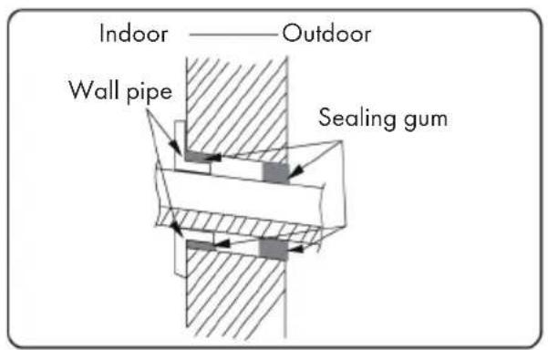
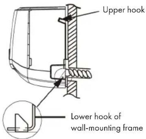
Step 9: Suspend the Indoor Air Conditioner
1 Put the bound pipes in the wall pipe and then make them pass through the wall hole.
2 Hang the indoor unit on the wall-mounting frame.
3 Stuff the gap between pipes and wall hole with sealing gum.
4 Fix the wall pipe.
5 Check if the indoor unit is installed firmly and closed to the wall.
After Installation
Check whether the requirements listed in the table are met or whether there are any malfunctions:
| To check Possible malfunction | |
| Has the device been securely installed? The unit may fall, wobble or make a noise during start-up. | |
| Would a refrigerant leak test be performed? | Insufficient cooling (or heating) capacity could result. |
| Have the lines been sufficiently insulated? Condensation and dripping water could result. | |
| Is the water drained correctly? Condensation and dripping water could result. | |
| Does the mains voltage of the socket correspond to the voltage indicated on the appliance's nameplate? | Malfunctions may be caused or parts of the unit may be damaged. |
| Have the electrical cables and lines been installed correctly? | Malfunctions may be caused or parts of the unit may be damaged. |
| Has the appliance been properly earthed? | This could result in electrical leakage. |
| Does the power cord used meet the manufacturer's requirements? | Malfunctions could be caused or parts of the device could be damaged. |
| Are the air inlets and outlets blocked by anything? | Insufficient cooling (or heating) capacity could result. |
| Have dust and dirt residues been removed during installation? | Malfunctions may be caused or parts of the unit may be damaged. |
| Are the gas valve and liquid valve fully open? | Insufficient cooling (or heating) capacity could result. |
| Have the inlet and outlet of the pipe opening been covered? | Insufficient cooling (or heating) capacity or waste of energy could result. |
INSTALLATION OF THE OUTDOOR UNIT
Important installation instructions

WARNING
Risk of injury! All persons involved in the installation of the air conditioning system MUST have the valid certifi cation of the responsible authority and the qualifi cation recognised by this industry for handling the refrigeration system.
- If other technicians are required for the maintenance and repair of the unit, they should be supervised by the person who has the qualification for the use of the combustible refrigerant.
- The air-conditioning system must only be repaired in accordance with the procedure laid down by the manufacturer of the appliance.
- The air conditioner must not be operated in rooms with open flame devices (such as fi replaces, running coal-gas appliances, running heaters, etc.).
- It is not permitted to drill into or expose the connecting pipe to fire.
- The air conditioner must be installed in a room larger than the specified minimum room size. The minimum room size is indicated on the nameplate or in the following table a.
- A leak test must be carried out after installation of the unit.
Minimum room size (^2)
Note: The actual device may differ from the illustrations above. Refer to your device.
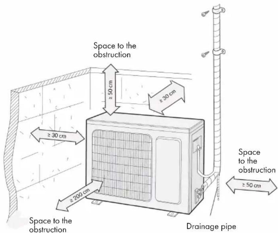
Installation Clearances
Before Installation
- When installing or relocating the unit, be sure to keep the refrigerant circuit free from air or substances other than the specified refrigerant. Any presence of air or other foreign substance in the refrigerant circuit will cause system pressure rise or compressor rupture, resulting in injury.
- When installing or moving this unit, do not charge the refrigerant which is not comply with that on the nameplate or unqualified refrigerant. Otherwise, it may cause abnormal operation, wrong action, mechanical malfunction or even series safety accident.
- When refrigerant needs to be recovered during relocating or repairing the unit, be sure that the unit is running in cooling mode. Then, fully close the valve at high pressure side (liquid valve). About 30-40 seconds later, fully close the valve at low pressure side (gas valve), immediately stop the unit and disconnect power. Please note that the time for refrigerant recovery should not exceed 1 minute. If refrigerant recovery takes too much time, air may be sucked in and cause pressure rise or compressor rupture, resulting in injury.
- During refrigerant recovery, make sure that liquid valve and gas valve are fully closed and power is disconnected before detaching the connection pipe. If compressor starts running when stop valve is open and connection pipe is not yet connected, air will be sucked in and cause pressure rise or compressor rupture, resulting in injury.
- When installing the unit, make sure that connection pipe is securely connected before the compressor starts running. If compressor starts running when stop valve is open and connection pipe is not yet connected, air will be sucked in and cause pressure rise or compressor rupture, resulting in injury.
- Prohibit installing the unit at the place where there may be leaked corrosive gas or flammable gas. If there leaked gas around the unit, it may cause explosion and other accidents.
-
Do not use extension cords for electrical connections. If the electric wire is not long enough, please contact a local service center authorized and ask for a proper electric wire. Poor connections may lead to electric shock or fire.
-
Use the specified types of wires for electrical connections between the indoor and outdoor units. Firmly clamp the wires so that their terminals receive no external stresses. Electric wires with insufficient capacity, wrong wire connections and insecure wire terminals may cause electric shock or fire.
Tools required for Installation
| 1 Spirit level 8 Pipe cutter | |
| 2 Screwdrivers 9 Leakage detector | |
| 3 Impact drill 10 Vacuum pump | |
| 4 Drilling head 11 Pressure meter | |
| 5 Pipe expander 12 Universal meter | |
| 6 Torque wrench 13 Inner hexagon spanner | |
| 7 Open-end wrench 14 Measuring tape |
Notes on the Installation Environment
- There must be no blockages or obstacles near the air intake.
- Select a place where the condensation can be easily distributed without adversely affecting other people.
- Select a location where the connection to the outdoor air conditioner can easily be established and which is close to an electrical outlet.
- Select a location that is out of the reach of children.
- The installation site should be able to support the weight of the indoor air conditioner and should not increase the noise level and vibration of the unit.
The unit must be installed at least 2.5 meters above the floor. - Do not install the indoor air conditioner directly above electrical equipment.
- Try to install the indoor air conditioner as far away from fluorescent lamps as possible.
Installing the unit in the following locations may result in malfunction of the unit. The following locations are not suitable for installation. If installation in any of these locations cannot be avoided, contact customer service before installation:
- Locations with strong sources of heat, vapors, flammable or explosive gases, or volatile objects dispersed in the air.
- Places where high frequency equipment is used (such as welding machines, medical equipment, etc.).
Places near the coast - Places where there are oils or vapours in the air.
- Places where sulphurous gases escape or are present.
- Places with similar conditions to those mentioned above.
The unit must not be installed in washrooms. - The unit must not be installed on unstable or moving structures (such as a truck) or in corrosive environments (such as a chemical plant).
Step 1: Installation of the support of the Outdoor Unit
1 Select installation location according to the house structure.
2 Fix the support of outdoor unit on the selected location with expansion screws.
Make sure that the wearer of the unit can carry at least 4 times the actual weight of the outdoor air conditioner.
The unit should be installed at least 3 cm above the floor so that the drain can be installed.
For units with a cooling capacity of 2300 W - 5000 W, 6 expansion screws are required.
For units with a cooling capacity of 6000 W - 8000 W, 8 expansion screws are required.
For units with a cooling capacity of 10000 W - 16000 W, 10 expansion screws are required.
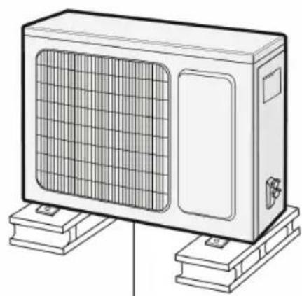
At least 3cm above the floor
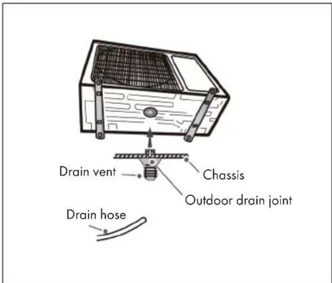
Step 2: Installation of the Drain Nozzle
(only for outdoor air conditioning systems with cooling and heating function)
1 Connect the outdoor drain joint into the hole on the chassis, as shown in the picture below.
2 Connect the drain hose into the drain vent.
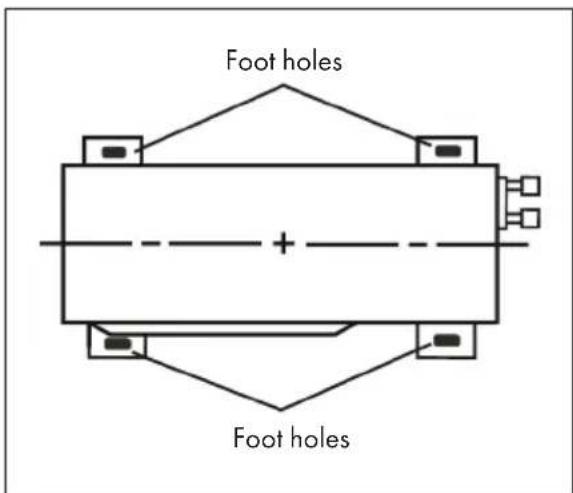
Step 3: Fixing the Outdoor Air Conditioner
1 Place the outdoor unit on the support.
2 Fix the foot holes of outdoor unit with bolts.
Step 4: Line Connection of the Outdoor Air Conditioner
| 1 | 2 |
| Screw Handle | Liquid valve Liquid pipe Gas pipe Gas valve |
| Remove the screw on the right handle of outdoor unit and then remove the handle. | Remove the screw cap of valve and aim the pipe joint at the bellmouth of pipe. |
| 3 | 4 |
| Pipe joint Union nut | Hex nut diameter Tightening torque |
| Ø 6 15 - 20 Nm | |
| Ø 9,52 30 - 40 Nm | |
| Ø 12 45 - 55 Nm | |
| Ø 16 60 - 65 Nm | |
| Ø 19 70 - 75 Nm | |
| Pretightening the union nut with hand. Tighten the union nut with torque wrench by referring to the sheet. | |
Step 5: Connecting the Electrical System of the Outdoor Air Conditioner
1 Remove the wire clip; connect the power connection wire and signal control wire (only for cooling and heating. Note: The terminal strip shown is for orientation only. Refer to the actual terminal block.
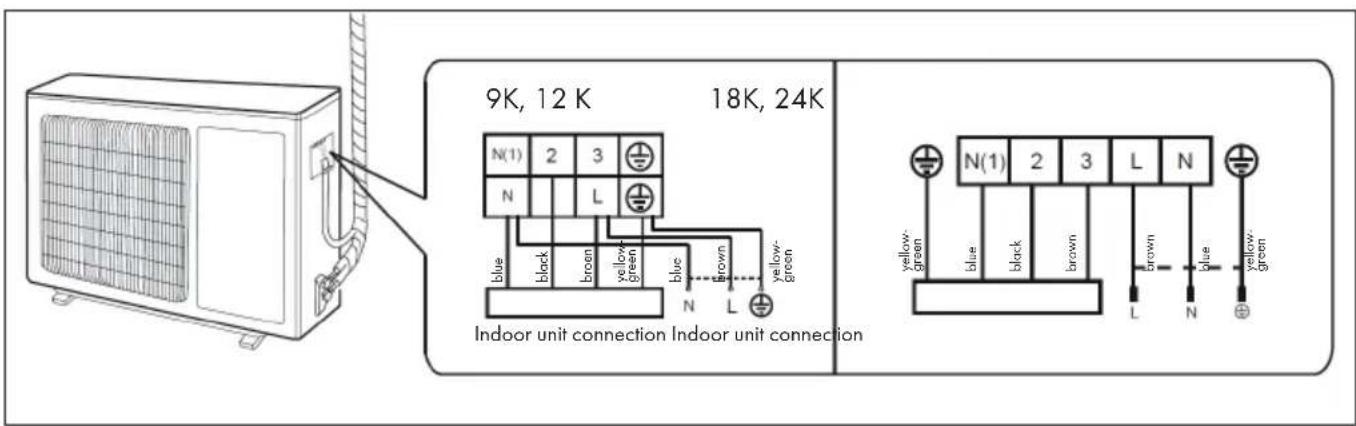
2 Fix the power connection wire and signal control wire with wire clip (only for cooling and heating unit).
Note: After tightening the screws, gently pull the power cord to check that it is properly tightened. Never cut the power cord to lengthen or shorten the cord.
Step 6: Neaten the Pipes
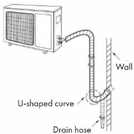
The cables should be bent and hidden as gently as possible and run along the wall. Do not bend the cables too much!
If the outdoor air conditioner hangs higher than the hole in the wall, you must insert a U-shaped bend into the pipe before it is led into the room to prevent rainwater from entering the room.
Important Notes on Arranging the Cables
| The through-wal height of drain hose shouldn't be higher than the outlet pipe hole of indoor unit. | Tilt the drain hose slightly downwards. The drain hose must not be bent, inclined upwards or corrugated, etc. | |
| The water outlet can't be placed in water in order to drain smoothly. | The drain hose must not be fluc- tuant. | The water outlet must not be fluctuant |
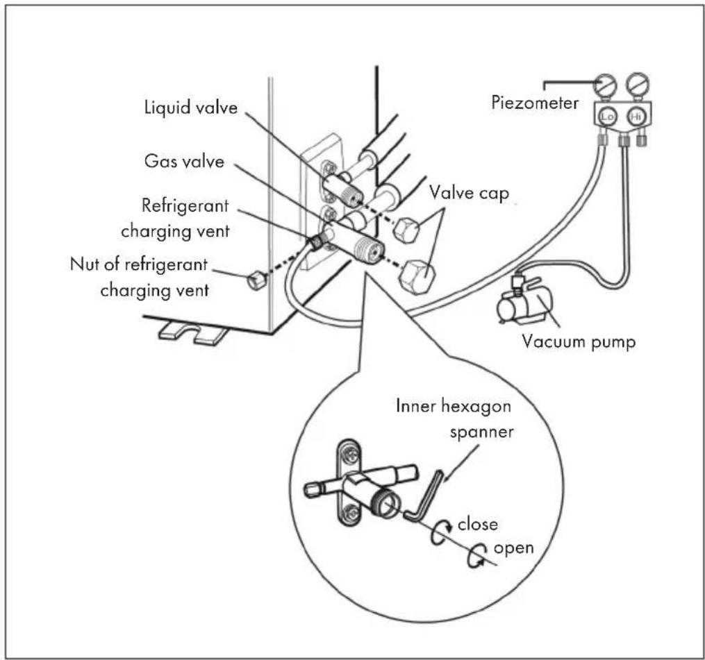
1 Remove the valve caps on the liquid valve and gas valve and the nut of refrigerant charging vent.
2 Connect the charging hose of piezometer to the refrigerant charging vent of gas valve and then connect the other charging hose to the vacuum pump.
3 Open the piezometer completely and operate for 10-15min to check if the pressure of piezometer remains in -0.1MPa.
4 Close the vacuum pump and maintain this status for 1-2min to check if the pressure of piezometer remains in -0.1MPa. If the pressure decreases, there may be leakage.
5 Remove the piezometer, open the valve core of liquid valve and gas valve completely with inner hexagon spanner.
6 Tighten the screw caps of valves and refrigerant charging vent.
Leakage Detection
With Leakage Detector
Check if there is leakage with leakage detector.
With soap water
If leakage detector is not available, please use soap water for leakage detection. Apply soap water at the suspected position and keep the soap water for more than 3min. If there are air bubbles coming out of this position, there's a leakage.
After installation
Check whether the requirements listed in the table are met or whether there are any malfunctions:
| To check Possible malfunction | |
| Has the device been securely installed? The unit | may fall, wobble or make a noise during start-up. |
| Would a refrigerant leak test be performed? Insufficient cooling or heating capacity could result. | Insufficient cooling or heating capacity could result. |
| Have the lines been sufficiently insulated? Condensation and dripping water could result. | Dripping water could result. |
| Is the water drained correctly? Condensation and dripping water could result. | Malfunctions may be caused or parts of the unit may be damaged. |
| Does the mains voltage of the socket correspond to the voltage indicated on the appliance's nameplate? | Malfunctions may be caused or parts of the unit may be damaged. |
| Have the electrical cables and lines been installed correctly? | Malfunctions may be caused or parts of the unit may be damaged. |
| Has the appliance been properly earthed? This could result in electrical leakage. | Malfunctions could be caused or parts of the device could be damaged. |
| Does the power cord used meet the manufacturer's requirements? | Insufficient cooling or heating capacity could result. |
| Are the air inlets and outlets blocked by anything? | Malfunctions may be caused or parts of the unit may be damaged. |
| Have dust and dirt residues been removed during installation? | Inadequate cooling or heating capacity could result. |
| Are the gas valve and liquid valve fully open? Inadequate cooling or heating capacity could result. | Inadequate cooling or heating capacity or waste of energy could result. |
| Have the inlet and outlet of the pipe opening been covered? |
TEST OPERATION
Preparation
- The client approves the air conditioner.
- Specify the important notes for air conditioner to the client.
Method of Test Operation
- Put through the power, press ON/OFF button on the remote controller to start operation.
- Press MODE button to select AUTO, COOL, DRY, FAN and HEAT to check whether the operation is normal or not.
Note: If the ambient temperature is lower than 16^ , the air conditioner can't start cooling.
CONFIGURATION OF THE CONNECTION PIPE
1. Standard length of connection pipe
5m / 7,5m / 8m
2. Min length of connection pipe
- For the unit with standard connection pipe of 5m , there is no limitation for the min length of connection pipe.
- For the unit with standard connection pipe of 7.5m and 8m , the min length of connection pipe is 3m .
3. Max length of Connection Pipe
The maximum length of the connection line depends on the capacity of the air conditioner (see table below).
| Capacity Max. length | Capacity Max. length | |
| 5.000 BTU/h (1465 W) 15 | 24.000 BTU/h (7032 W) 25 | |
| 7.000 BTU/h (2051 W) 15 | 28.000 BTU/h (8204 W) 30 | |
| 9.000 BTU/h (2637 W) 15 | 36.000 BTU/h (10548 W) 30 | |
| 12.000 BTU/h (3516 W) 20 | 42.000 BTU/h (12306 W) 30 | |
| 18.000 BTU/h (5274 W) 25 | 48.000 BTU/h (14064 W) 30 |
4. The calculation method of additional refrigerant oil and refrigerant charging amount after prolonging connection pipe
After the length of connection pipe is prolonged for 10m at the basis of standard length, you should add 5ml of refrigerant oil for each additional 5m of connection pipe. The calculation method of additional refrigerant charging amount (on the basis of liquid pipe):
- Additional refrigerant charging amount = prolonged length of liquid pipe × additional refrigerant charging amount per meter.
- Basing on the length of standard pipe, add refrigerant according to the requirement as shown in the table. The additional refrigerant charging amount per meter is different according to the diameter of liquid pipe.
Note: The information on the additional quantity of coolant is recommended and is not mandatory.
| Diameter of connection pipe (mm) Indoor | unit throttle Outdoor unit throttle | |||
| Liquid pipe Gas pipe Cooling only, | cooling and heating(g/m) | Cooling only(g/m) | Cooling and heating (g/m) | |
| Ø 6 Ø 9,5 or Ø 12 16 12 16 | ||||
| Ø 6 or Ø 9,5 Ø 16 or Ø 19 | 40 | 12 40 | ||
| Ø 12 | Ø 19 or Ø 22,2 | 80 | 24 | 96 |
| Ø 16 | Ø 25,4 or Ø 31,8 | 136 | 48 | 96 |
| Ø 19 | X | 200 | 200 | 200 |
| Ø 22,2 | X | 280 | 280 | 280 |
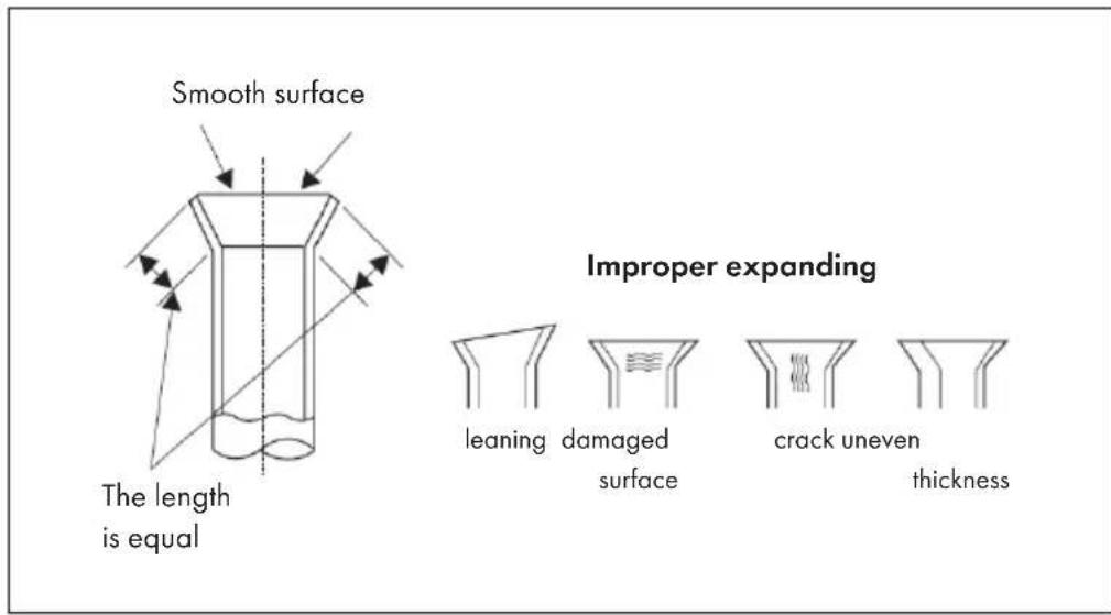
Pipe Expanding Method
Note: Improper pipe expanding is the main cause of refrigerant leakage. Expand the pipe according to the following steps:
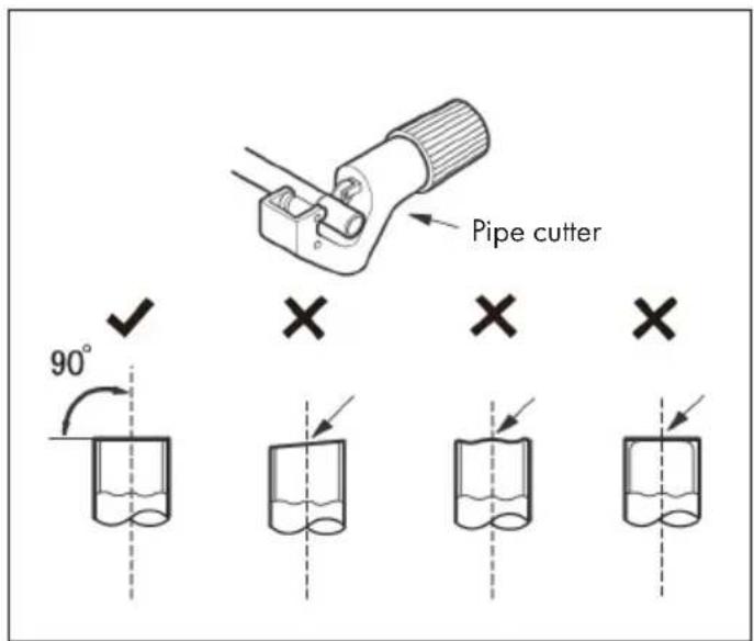
(A) Cut the Pipe
Determine the line length based on the distance between the indoor and outdoor air conditioners. Cut the required cable length with a cable cutter.
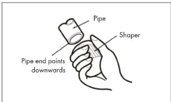
(B) Remove the Burrs
Remove the burrs with a shaper. Make sure that the end of the line is pointing downwards towards the top of the shaper to prevent dust from getting back into the line.
(C) Put on the Union Nut
Put on suitable insulating pipe. Remove the union nut on the indoor connection pipe and outdoor valve. Install the union nut on the pipe.
(D) Expand the Port
Expand the port with expander.
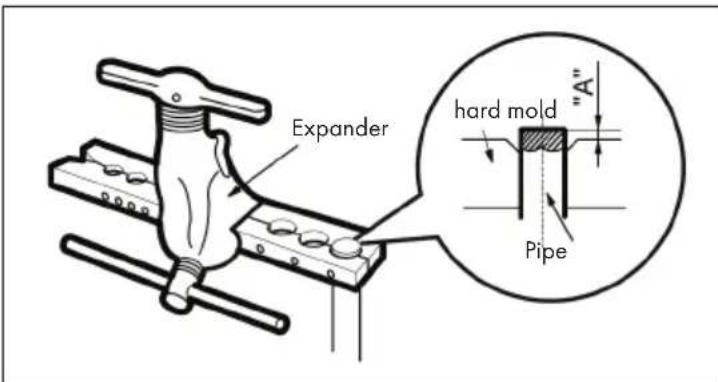
"A" is different according to the diameter, please refer to the sheet below:
| Outer diameter (mm) | A (mm) | |
| Max Min | ||
| Ø 6 - 6,35 (1/4") 1,30,7 | ||
| Ø 9,52 (3/8") 1,61,0 | ||
| Ø 12 - 12,7 (1/2") 1,81,0 | ||
| Ø 15,8 - 16 (5/8") 2,42,2 | ||
(E) Inspection
Check the quality of expanding port. If there is any blemish, expand the port again according to the steps above.
CLEANING AND MAINTENANCE
Important Cleaning Instructions
- Turn off the air conditioner and unplug the power cord from the wall outlet before cleaning the air conditioner to prevent electric shock.
- To avoid electric shock, do not wash the air conditioner with water.
- Do not use volatile liquids to clean the air conditioner.
Surface Cleaning of the Indoor Air Conditioner
If the surface of the indoor air conditioner is dirty, it is recommended to wipe it with a soft dry or damp cloth.
Note: Do not remove the cover for cleaning.
Filter Cleaning
- The filter should be cleaned every three months. If there is a lot of dust in the area where the air conditioner is used, the filter should be cleaned more frequently.
- Be careful not to touch the blades after removing the filter to avoid injury.
- Never dry the filter with a fire or hairdryer as this could deform the filter and create a fire hazard.
| 1 | 2 |
| Open the cover to a certain angle as shown in the illustration. | Remove the filter as shown in the figure. |
| 3 | 4 |
| Use a dust collector or water to clean the filter. If the filter is very dirty, use water (below 45℃) to clean it and place the filter in a shady and cool place to dry. | Replace the filter and close the cover tightly. |
At the End of the Season
Proceed as follows according to the season in which the air conditioner is used:
- Disconnect the mains plug from the socket.
- Clean the filter and the cover of the indoor air conditioner.
- Check whether the suspension of the outdoor air conditioner is damaged or rusted. If so, contact customer service.
At the Beginning of the Season
Check the following before the air-conditioning season:
- Check that the air inlets and outlets are blocked.
- Check that the ventilation switch, mains plug and socket are in good condition.
- Check that the filter is clean.
- Check whether the suspension of the outdoor air conditioner is damaged or rusted. If so, contact customer service.
- Check whether the water drain pipe is damaged.
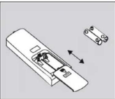
Replacing the Remote Control Batteries
On the back of the remote control, as shown in the illustration, press down on the location where the "OPEN" mark is located, then slide down the battery compartment cover in the direction of the arrow. Replace the two batteries (AAA 1.5 V) with two batteries of the same type and make sure the polarity is correct. Replace the battery compartment cover.
- When using the remote control, the signal transmitter of the remote control should be aimed at the reception window of the indoor air conditioner.
- The distance between the signal transmitter and the reception window should not exceed 8 m and there should be no obstacles in between.
- The signal may be easily affected in rooms with fluorescent lamps or cordless phones. The remote control should be close to the air conditioner when in use.
- Replace batteries with batteries of the same type when changing batteries becomes necessary.
- Remove the batteries from the battery compartment if you will not be using the remote control for an extended period of time.
- If the remote control screen is out of focus or shows nothing, replace the batteries.
Maintenance
- Check that the maintenance area or room in which the air conditioner is serviced meets the requirements on the nameplate. Maintenance may only be carried out in areas that meet these requirements.
- Ensure that there is adequate ventilation of the maintenance area during all maintenance work.
- Ensure that there are no fire sources or potential fire sources in the service area. Open flames are prohibited throughout the service area. It is recommended that you hang a No Smoking sign.
- Check that the appliance label is in good condition. Replace hard-to-read or damaged equipment labels.
Filling the Refrigerant
- Use the refrigerant R32 suitable for the unit. Make sure that you do not mix different refrigerants.
- The refrigerant tank should be kept straight throughout the time the refrigerant is being charged into the air conditioner.
- Stick a sticker with the refrigerant label on the air conditioner.
- Do not pour too much refrigerant into the air conditioner.
After you have filled the refrigerant into the air conditioner, carry out a leak test. A leak test should also be carried out before removing the refrigerant.
Transporting and Storing the Refrigerant Tank
- Use a flammable gas detector before unloading and opening the refrigerant container.
- Fire sources and smoking are prohibited during transport and in the storage area of the container.
- Follow local laws and regulations.
TROUBLESHOOTING
| Problem Possible Cause Suggested Solution | ||
| The indoor air conditioner cannot receive the remote control signal or the remote control cannot be operated. | Interference due to electrostatic charging, constant voltage etc. | Disconnect the mains plug from the socket. After 3 minutes, plug the mains plug back into the socket and switch on the device again. |
| The remote control is out of range of the unit. | The maximum signal range is 8 meters. | |
| There are obstacles between the remote control and the air conditioner. | Remove the obstacles. | |
| The remote control is not directed at the reception window of the air conditioner. | Hold the remote control at the correct angle to the receiver window of the air conditioner. | |
| The sensitivity of the remote control is reduced and the screen is blurred or does not display at all. | Check the batteries. If the batteries are empty, replace them. | |
| The remote control screen does not display anything. | Check if the remote control is damaged. If so, replace them. | |
| There are fluorescent lamps in the room where the air conditioner is installed. | Place the remote control near the air conditioner. If it still does not work, turn off the lights and try again. | |
| The air conditioner doesn't give off any air. | The air inlet or outlet of the air conditioner is blocked. | Remove the blockade. |
| In heating mode, the room temperature has reached the temperature set on the air conditioner. | After the room temperature reaches the temperature set on the air conditioner, the unit stops blowing air. | |
| The heating mode has just been activated. | To prevent cold air from being blown out in heating mode, warm air is delayed by a few minutes. This is a normal process. | |
| The air conditioner cannot be operated. | There is a power failure. Wait until the power failure is over. | |
| The mains plug is loose. Insert the mains plug correctly into the socket. | ||
| The ventilation switch is defective or the fuse has blown. | Have a qualified person replace the ventilation switch or fuse. | |
| The wiring has malfunctions. | Have the wiring replaced by a qualified person. | |
| The device was switched on again immediately after it was switched off. | Wait three minutes after turning off the unit before turning it back on. | |
| The function setting of the remote control is not set correctly. | Reset the functions to their factory defaults. | |
| Problem Possible Cause Suggested Solution | ||
| Water vapour comes out of the air outlet of the indoor air conditioner. | The indoor temperature and humidity are very high. | |
| The set temperature cannot be adjusted. | The temperature you wish to set is outside the adjustable range. | |
| The cooling / heating effect is not good. | The voltage is too low. Wait until the voltage returns to normal. | |
| The filter is dirty. Clean the filter. | ||
| The set temperature is outside the temperature range. | ||
| Doors or windows are open. | ||
| The air conditioner emits an unpleasant smell. | The smell of furniture, cigarettes etc. is sucked in by the air conditioner and blown out with the air. | |
| The air conditioner does not work properly. | Interferences such as thunderstorms, mobile devices etc. influence the function of the air conditioner. | |
| The sound of running water can be heard. | The air conditioner has just been turned on or off. | |
| A cracking noise can be heard. | The air conditioner has just been turned on or off. | |
Error Codes
| E 5 | This error can usually be corrected by restarting the device. If not, contact customer service. |
| E 8 | This error can usually be corrected by restarting the unit. If not, contact customer service. |
| U 8 | This error can usually be corrected by restarting the machine. If not, contact customer service. |
| H 6 | This error can usually be corrected by restarting the machine. If not, contact customer service. |
| C 5 | Contact customer service. |
| F 0 | Contact customer service. |
| F 1 | Contact customer service. |
| F 2 | Contact customer service. |
| H 3 | This error can usually be corrected by restarting the unit. If not, contact customer service. |
| E 1 | This error can usually be corrected by restarting the machine. If not, contact customer service. |
| E 6 | This error can usually be corrected by restarting the machine. If not, contact customer service. |
DISPOSAL CONSIDERATIONS
If there is a legal regulation for the disposal of electrical and electronic devices in your country, this symbol on the product or on the packaging indicates that this product must not be disposed of with household waste. Instead, it must be taken to a collection point for the recycling of electrical and electronic equipment. By disposing of it in accordance with the rules, you are protecting the environment and the health of your fellow human beings from negative consequences. For information about the recycling and disposal of this product, please contact your local authority or your household waste disposal service.
This product contains batteries. If there is a legal regulation for the disposal of batteries in your country, the batteries must not be disposed of with household waste. Find out about local regulations for disposing of batteries. By disposing of them in accordance with the rules, you are protecting the environment and the health of your fellow human beings from negative consequences.
MANUFACTURER & IMPORTER (UK)
Manufacturer:
Chal-Tec GmbH, Wallstrasse 16, 10179 Berlin, Germany.
Importer for Great Britain:
Berlin Brands Group UK Ltd
PO Box 1145
Oxford,OX1 9UW
United Kingdom
Estimado cliente,
Berlin Brands Group UK Ltd
PO Box 1145
Oxford,OX19UW
United Kingdom
Chere cliente, cher client,
Berlin Brands Group UK Ltd
PO Box 1145
Oxford,OX19UW
United Kingdom
Gentile cliente,
PRODUTTORE IMPORTATORE (UK)
Produttore:
Chal-Tec GmbH, Wallstraße 16, 10179 Berlin, Germania.
Berlin Brands Group UK Ltd
PO Box 1145
Oxford,OX1 9UW
United Kingdom


KLARSTEIN