Lumina 48 XL Intensive - Solar bench Hapro - Free user manual and instructions
Find the device manual for free Lumina 48 XL Intensive Hapro in PDF.
| Product type | Sunbed (tanning cabin) |
| Brand | Hapro |
| Model | Lumina 48 XL Intensive |
| Warranty | 1 year (factory warranty) |
| Power supply | 230 V, GFCI protection 0.03 A |
| External timer required | Yes |
| Minimum rear distance | 30 cm from wall |
| Maximum ambient temperature | 30 °C |
| Acrylic sheet replacement | Every 1200 hours of use |
| Recommended cleaner | Special acrylic cleaner (no alcohol) |
| Lamp type | Low pressure, replace with lamps of the same type |
| Starters | Turn 1/4 turn to remove/replace |
| Eye protection | UV protective goggles mandatory |
| Ventilation | Must operate optimally |
| Acrylic sheet mandatory | Yes, do not use without sheet |
| Available options | Xsense module, coin acceptor, audio |
| Initial time reduction | Reduce by 20% for the first 50 hours of lamp use |
| Minimum user age | 15 years |
| Allowed skin types | 2 to 6 (type 1 excluded) |
| Maximum number of sessions per year | Approximately 50 sessions (including natural sun exposure) |
Frequently Asked Questions - Lumina 48 XL Intensive Hapro
User questions about Lumina 48 XL Intensive Hapro
0 question about this device. Answer the ones you know or ask your own.
Ask a new question about this device
Download the instructions for your Solar bench in PDF format for free! Find your manual Lumina 48 XL Intensive - Hapro and take your electronic device back in hand. On this page are published all the documents necessary for the use of your device. Lumina 48 XL Intensive by Hapro.
USER MANUAL Lumina 48 XL Intensive Hapro
natural_image
Exterior view of a modern office building (no signage)48XL
48 XL INTENSIVE
48 XLC
48 XLc INTENSIVE
Lumina
Before obtaining access to terminals, all supply circuits must be disconnected
▶ Contents
Warranty policy ....2
Read this first ....3
10 Golden rules for sensible tanning in the tanning unit .....4
Users instructions
- Removing the acryl panels ....5
- Operation ....6
Tanning tables 37
Line-up / Dimensions ....38
Assembly tanning unit ....39
Technical data 47
Electrical diagrams 48
Spare part list ....53
▶ Warranty
We would like to congratulate you on the purchase of your Lumina tanning unit and thank you for placing your trust in us.
Our tanning units are manufactured with the greatest attention and are of excellent quality.
Every Lumina is manufactured to meet the international IEC/EN standards and carries the Kema seal of approval. We provide a manufacturer's warranty of 1 year.
The guarantee commences from the date of purchase. Within the period under guarantee we will repair free of charge, any malfunction resulting from faulty materials or manufacturing. For work to be carried out under the guarantee you should contact your dealer.
In order to make a claim under the terms of this guarantee, you must be able to produce the original invoice or receipt bearing the date of purchase. The type and serial number of the appliance should also be indicated.
The warranty is subordinate to the national regulations according to the warranty determination of products.
▶ Not covered under this warranty:
- Units which have the type, serial number and/or other identification labels removed, damaged or altered.
- Lamps, starters and acrylic sheets.
- Damage due to purchaser abuse, neglect, transport, improper use or improper maintenance.
- Damage due to use of accessories not originally supplied by Hapro or inferior accessories.
- Damage due to installation, repair or assembly not done by Hapro authorised personnel.
- Damage due to fire, lightning, earth-quakes or other natural disasters.
▶ Read this first
1 Contact your authorised Hapro dealer immediately if this unit does not function as outlined in this manual.
2 Do not operate this unit in a moist or humid space.
3 Always make sure the fuses can carry the load. This unit has to be protected by ground fault circuit interrupter (GFCI) of 0.03A.
If the appliance is not connected by means of a plug, an installation device or an all-pole working switch will need to be fitted.
4 Always disconnect the power to the unit at the wall breaker when servicing or cleaning the in-side construction of the cabine. Maintenance for which the procedure is not described in this manual should only be done by a qualified electrician.
Never clean the electrical components with fluids.
5 When installing the equipment, keep in mind the prescribed minimum distances as described in the "Dimensions / Placement" chapter.
6 If the equipment is being placed in a cubic, there should be enough space between the walls and the equipment, preferably the minimum amount as indicated in the "Assembly of Tanning Equipment". This has to do with the air circulation surrounding the equipment.
7 Avoid having the acrylic sheets come into-contact with sharp objects.
8 This unit may not be operated if:
- the user is not wearing protective uv-goggles
• the canopy acrylic sheet is not installed
- The acryl panel is not present in the tanning unit.
- the temperature inside the cabin is 30^ C or higher
- The Lumina should in all cases be connected to an external timer.
9 Exchanging lamps and starters; remove the lamp by turning this a quarter turn to the left. Remove the starters by turning these a quarter turn to the left. Placement of lamps and starters in opposite order.
10 Replace the acryl panels every 1200 operating hours for optimum effectiveness of the unit.
11 Replace, for optimum effectiveness, the low-pressure lamps as stipulated by the manufacturer. Replace only by the same type of lamp.
12 Check the environment regulations of your respective state with regard to the proper manner in which the lamps are to be disposed of.
13 Note: only a special acrylic cleaner may be used to clean the acrylic sheet. Never use cleaners that contain alcohol, as these can damage the acrylic plate.
14 The UV-type of the tanning unit is indicated on the specificationsticker.
15 Ultraviolet radiation from the sun or UV appliances can cause skin or eye damage. These biological effects depend upon the quality and quantity of the radiation as well as the skin and eye sensitivity of the individual.
16 The skin may develop sunburn after an excessive exposure. Excessively repeated exposures to ultraviolet radiation from the sun or UV appliances may lead to premature ageing of het skin as well as increased risk of development of the skin tumours.
17 The unprotected eye may develop surface inflammation and in some cases, after a cataract operation for example, damage may occur to the retina after excessive exposure. Cataracts may develop after many repeated exposures.
18 If the supply cord is damaged, it must be replaced by the manufacturer or its service agent or a similarly qualified person in order to avoid a hazard.
▶ Note:
Please consult enclosed tanning schedule for advised tanning times.
Repairs may only be carried out by qualified personnel. Always disconnect the main power at the circuit breaker before servicing or repairing the unit.
▶ 10 Golden rulesfor sensible tanning
These rules are in accordance with the European regulations concerning safe use of tanning equipment. We advise you to inform your clients about these rules.
1 Before starting to tan first carefully read through the tanning instructions set out in this booklet and follow all of the recommendations.
2 Restrict sunbathing on a tanning unit to people older than 15 years with skin type 2 - 6. Children younger than 15 year and people with skin type 1 have skins that are highly sensitive to ultraviolet light.
3 Make sure that upon commencing a series of tanning sessions your customers have a rest day following their first tanning session. If there is no sign of any undesirable skin reaction they can then continue with the series of sessions.
4 Make sure that your customers do not tan more than once a day. This applies to tanning on the sunappliance and tanning in natural sunlight. The skin does not make a distinction between the two either. Taking exposure to natural sunlight into account, keep the maximum number of sessions on the sunappliance to approximately 50 sessions a year.
5 Some medicines and beauty products contain substances which can cause certain undesirable reactions when combined with exposure to UV radiation. Other substances may also sometimes have a similar effect. Below you will find a list of substances which can react when combined with exposure to UV radiation:
- Sulphonamide - in various medicines including antibiotics
- Tetracyclines - in antibiotics, antiacne preparations
- Nalidexine acid - in medication for infection of the urinary passages
- Chlorothiazide - in diuretics
• Sulphonylurea - in diabetic medication
• Phenothiazines - anti-stress medication
• Triacetyldiphenylisatine - in laxatives
- Psoralenes - in tanning accelerators
• Cyclamates - in sweeteners
- Para-aminobenzoic acid (PABA) - in sun protection creams/oils
• Musk ambrette, musk oil - in perfumes
- Bleaching agents - in washing powders/liquids
- Eosine - in colourings
- Halogenated salicylamide - in antifungal substances
If your customers are using medication, ask them to consult their doctor before embaking on a series of tanning sessions.
6 When combined with exposure to ultraviolet light, cosmetic products - perfumes and make-up, can cause the skin to react. So take care to ensure that your skin is clean before tanning. Some products penetrate deep into the skin. Advise your customers to ensure that their skin is clean when tanning. Recommend that they clean their skin thoroughly a few hours before each tanning session, or better still, recommend that they wear no make-up at all the day before. Also advise your customers to remove any jewellery before tanning.
7 Make sure that your customers do not use cream or oil that contains a sun block or self-tanning lotion when using the tanning equipment. These products contain substances which influence tanning times and thus make the prescribed times unreliable. Also make sure that your customers do not use tanning pills in combination with a series of tanning sessions or exposure to natural sunlight. The combination of tanning pills and UV light can increase the possibility of skin irritation and sunburn.
8 If the skin is red and tout a short time after the tanning session it is likely to be sunburnt. Wait for these symptoms to disappear before tanning again, revise the tanning plan and reduce the length of the individual tanning sessions for the customer in question. If tanning gives rise to undesirable reactions that you cannot explain, stop the series of tanning sessions and advise your customer to see their doctor if the symptoms do not disappear within a short space of time.
9 Make sure that your customers always wear protective goggles to protect their eyes - even if you may have seen pictures of people tanning without using these goggles. UV light which directly enters the eyes can cause eye disorders (snow blindness, actinic conjunctivitis or cataracts).
10Reduce the tanning time by 20% during the first 50 hours that the (new) sunappliance is in use. During these first 50 hours the tubes do not emit the normal 100% energy but 120% energy. After the first 50 hours the tubes will emit the normal capacity of between 95% to 100%.
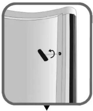
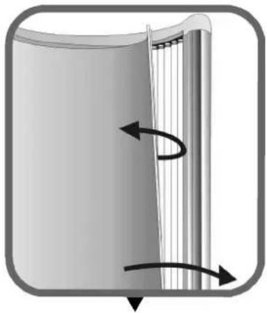
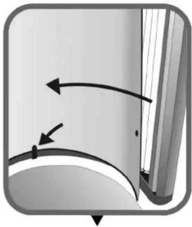
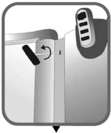
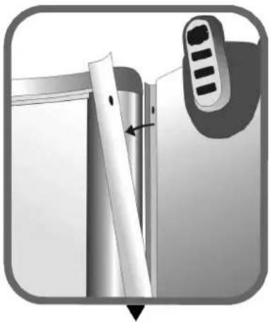
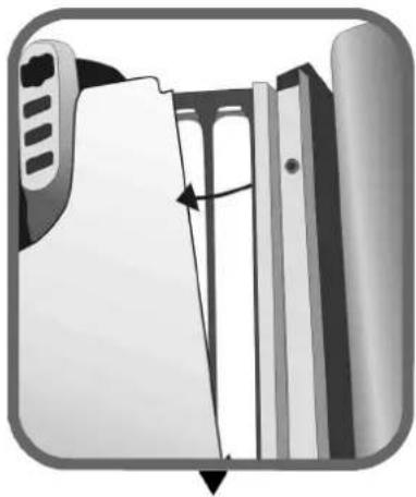
▶Removing the acrylic panels
natural_image
Diagram of a door with a scroll wheel and arrow indicating rotation (no text or symbols)Loosen the two rapid-action connectors.
natural_image
Diagram of a cylindrical object with internal vertical structure and curved arrows indicating rotation (no text or symbols)Remove the acryl panel.
natural_image
Diagram showing curved arrows indicating motion or direction, with no visible text or symbolsWhen replacing the acryl panel, place it behind the lip.
natural_image
Diagram showing a device with a scroll wheel and directional arrow, no text or symbols presentLoosen the six screws.
natural_image
Close-up of a mechanical component with a tool and a control knob, no visible text or symbolsRemove the aluminium profiles.
natural_image
Diagram of a mechanical assembly with a directional arrow indicating movement (no text or symbols present)Remove the acryl panel.
natural_image
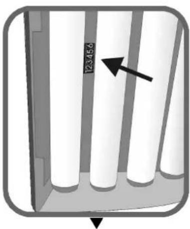
Diagram of vertical cylindrical structures with an arrow pointing to one (no text or symbols present)Read the hour counter.
natural_image
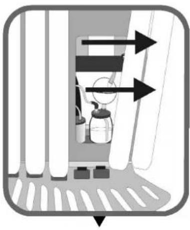
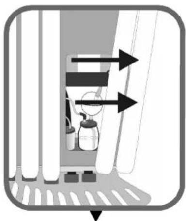
Diagram of a spray bottle inside a container with directional arrows indicating flow or movement (no text or symbols)Remove the lamps to replace the Xsens flacon.
natural_image
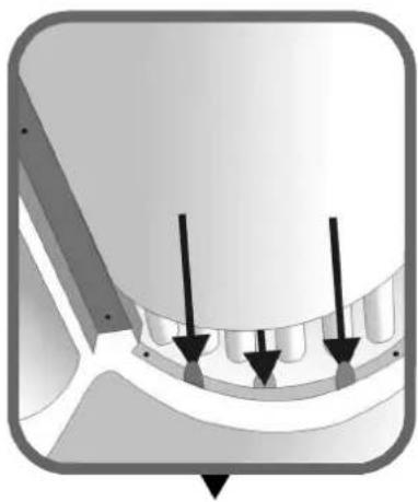
Diagram of a dental implant or implant component with three arrows indicating specific features (no text or symbols present)When fitting the acryl panel, place it between the lips.
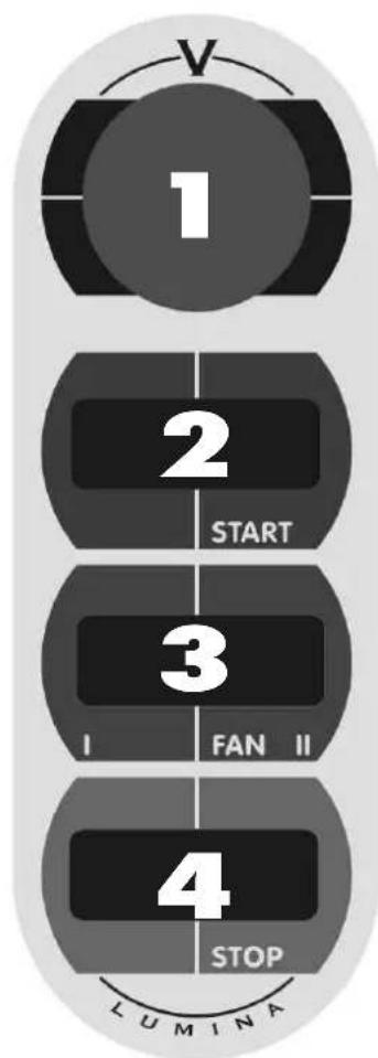
1 ▶
display of the operating panel (minutes, elapsed)
2▶
Starting the tanning unit when using a remote timer with quick start function.
3 ▶
Increasing or decreasing the air flow to the body. Adjustable in two stages.
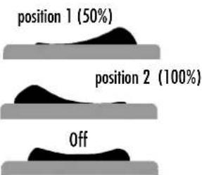
text_image
position 1 (50%) position 2 (100%) Off4
Turning off the tanning unit.
flowchart
graph TD
    A["1"] --> B["2"]
    B --> C["3"]
    C --> D["4"]
    D --> E["LUMINA"]
▶ Achtung!
natural_image
Illustration of a door handle with a scroll wheel and arrow indicator (no text or symbols)natural_image
Diagram of a mechanical or fluidic component with directional arrows indicating flow or movement (no text or symbols)natural_image
Diagram showing curved arrows indicating motion or direction, no text or symbols presentnatural_image
Diagram showing a device with a scroll wheel and directional arrow, no text or symbols presentnatural_image
Close-up of a mechanical component with a ruler and adjustment knob, no visible text or symbolsnatural_image
Diagram of a file folder with an arrow indicating a folding or alignment process (no text or symbols present)natural_image
Diagram of a mechanical component with vertical cylindrical parts and an arrow indicating direction (no text or symbols)natural_image
Diagram of a spray bottle inside a window with directional arrows indicating flow or movement (no text or symbols)natural_image
Diagram of a mechanical component with three arrows indicating direction, no visible text or symbolstext_image
3▶ Stand 1 (50%) Stand 2 (100%) Ausnatural_image
Illustration of a door with a scroll wheel and a black handle, showing no text or symbolsnatural_image
Diagram of a mechanical or structural component with directional arrows indicating rotation or force (no text or symbols)natural_image
Diagram showing curved arrows and a small mark on a surface, no text or symbols presentnatural_image
Diagram showing a door handle with a scroll wheel and directional arrow indicating rotation (no text or symbols)natural_image
Diagram showing a device with a scroll and a control panel, no text or symbols presentnatural_image
Diagram of a file folder with an arrow indicating a folding or movement process (no text or symbols present)natural_image
Diagram of a vertical panel with four white cylindrical cells and an arrow pointing to one (no text or symbols)Aflezen urenstand
natural_image
Diagram of a door with spray bottles and directional arrows indicating flow or movement (no text or symbols)natural_image
Diagram of a mechanical component with three arrows indicating direction (no text or symbols present)Alignment / Dimensions ....38
natural_image
Illustration of a door with a scroll wheel and arrow indicating rotation (no text or symbols)natural_image
Diagram of a mechanical or fluidic component with directional arrows indicating flow or movement (no text or symbols)natural_image
Diagram showing curved arrows indicating motion or force direction, no text or symbols presentnatural_image
Diagram showing a door handle mechanism with a scroll and directional arrow (no text or symbols)natural_image
Close-up of a mechanical component with a tool and arrow indicating a section (no visible text or symbols)natural_image
Diagram of a file folder with an arrow indicating a folding or alignment process (no text or symbols present)natural_image
Diagram of a cabinet or storage unit with vertical white pipes and an arrow pointing to one (no text or symbols)natural_image
Diagram of a mechanical or fluid system with directional arrows and components inside a chamber (no text or symbols)natural_image
Pure mechanical component diagram without any text, numbers, or symbolsnatural_image
Illustration of a door with a scroll wheel and arrow indicating rotation (no text or symbols)natural_image
Diagram of a cylindrical object with internal vertical structure and curved arrows indicating rotation (no text or symbols)natural_image
Diagram showing curved arrows and a rectangular object with a vertical line, no text or symbols presentnatural_image
Diagram showing a device with a scroll wheel and directional arrow, no text or symbols presentnatural_image
Close-up of a mechanical component with a tool and arrow indicating a step, no visible text or symbolsnatural_image
Diagram of a file folder with an arrow indicating a folding or movement (no text or symbols present)natural_image
Diagram of a cabinet or storage unit with vertical cylindrical elements and an arrow pointing to one (no text or symbols present)natural_image
Diagram of a spray bottle inside a container with directional arrows indicating flow or movement (no text or symbols)natural_image
Diagram of a mechanical component with three arrows indicating direction (no text or symbols present)natural_image
Diagram of a door with a scroll wheel and a curved arrow indicating rotation (no text or symbols)natural_image
Diagram of a mechanical or structural component with directional arrows indicating rotation or force (no text or symbols)natural_image
Diagram showing curved arrows and a small dot on a surface, no text or symbols presentnatural_image
Diagram showing a door handle mechanism with a scroll and directional arrow (no text or symbols)natural_image
Diagram showing a device with a scroll and a control panel, no text or symbols presentnatural_image
Diagram of a file folder with an arrow indicating a folding or alignment process (no text or symbols present)natural_image
Diagram of a spray bottle inside a window with directional arrows indicating flow or movement (no text or symbols)natural_image
Diagram of a mechanical component with three arrows indicating direction (no text or symbols present)Tanningtable
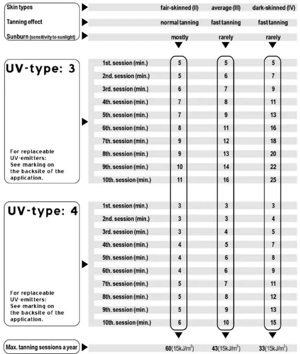
Warning!: Allow at least 48 hours between the first two exposures.
Warning!: UV-typ 4 may only be used following medical advice.
Lumina
▶ Assembly tanning unit
natural_image
Mechanical frame structure diagram with rotational arrows indicating motion (no text or symbols)GB Put the base on the floor and keep the back at least 30 cm form the wall. Turn the placing feet until the base is completely level.
Turn the column around in the box. Then unscrew the 10 bolts [M6 x 12] of the VSA plates and remove the profile (1). Loosen the 4 VSA plate plugs and remove the VSA plates.
Place the column on the base and attach this with 4 rings and 4 bolts [M8]. Replace the VSA plates in order (number 1 on the left). Attach the profile with the corresponding bolts. Then connect the plugs of the electric plate to the corresponding VSA plates.
D
text_image
Diagram illustrating a laboratory setup with two setups: one showing a test tube with two test probes, the other showing a gas collection bottle with a round-bottom flask.(optional) Attach the tray of the Xsens module to the lowest electric plate, with 2 spring rings and 2 bolts [M4 x 10]. Put the Xsens module in the tray.
natural_image
Diagram of a laboratory setup with a gas collection bottle, tubing, and control panel (no text or labels)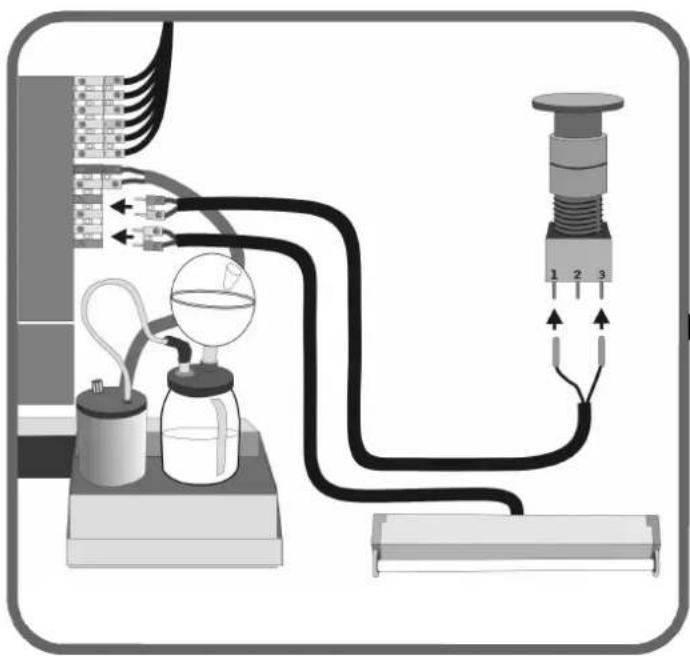
natural_image
Diagram of a laboratory apparatus with tubing, condenser, and pressure gauge (no text or labels)(optional) GB Connect the plugs of the emergency stop and the decorative lamp. See the image. Note; match the colors.
natural_image
Diagram of a mechanical linkage system with arrows indicating motion (no text or symbols)GB
Click the hinge rods into place onto the bearing heads of the spring.
F
Place the metal plate on the base and hold this in place with 4 sunk bolts [ M6 x 25 ].
D
natural_image
Mechanical diagram showing a rotating platform with arrows indicating rotational motion (no text or symbols)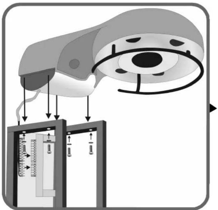
text_image
Diagram illustrating a medical procedure involving an eye with measurement scales and instrument placement, showing directional arrows and measurement indicators.GB
Position the blower hood on the column and attach this with 4 bolts [M6 x 55] and 4 rings. Connect 2 plugs to the left of the electric plate. Note: match the colors.
F
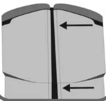
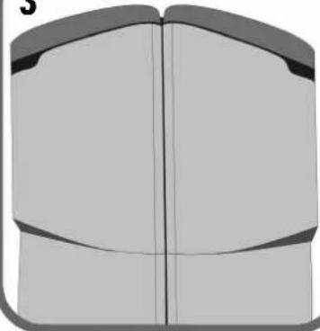
If the doors do not hang equally (see example 1) the doors can be adjusted (see example 3) by turning the excenters (see example 2).
D
natural_image
Diagram of a mechanical device with rotating arrow and base, enclosed in a rounded square frame (no text or symbols)1
natural_image
Pure diagram of a mechanical component with two vertical arrows indicating direction (no text or symbols)3
natural_image
Pure diagram of a symmetrical mechanical or architectural component with no text, numbers, or symbols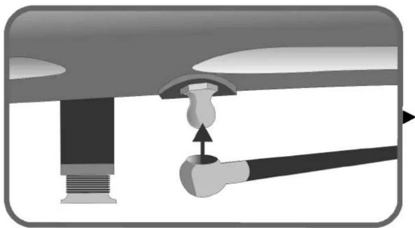
natural_image
Diagram of a mechanical assembly with a lever and handle, showing a pivot point (no text or symbols present)GB
Click the 2 hinge rods onto the baring heads on the bottom of the right and left doors.
D
natural_image
Mechanical assembly diagram showing a connector with rotating shafts and directional arrows (no text or symbols)GB Mount the cable of both doors on the column and lead the cable behind the hinge tube as indicated.
Connect the plugs of the left cable to VSA plates 1 and 2 and to the electric plate. Connect the plugs of the right cable to VSA plates 3 and 4 and to the electric plate. Note: match the colors. Make sure that the wiring is at all times free from sharp edges.
D
text_image
Diagram of an electrical panel with labeled components and wiring connections, showing connections between terminals 1-3.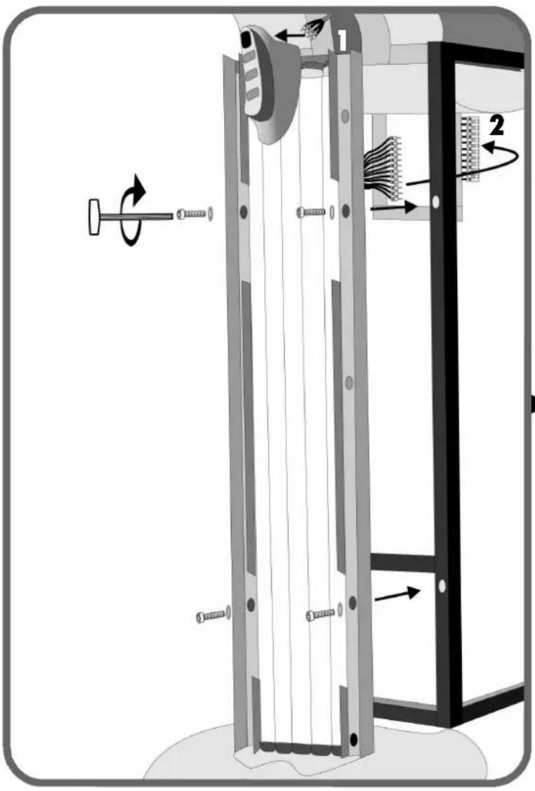
text_image
Technical diagram of a mechanical device with labeled components and directional arrows indicating motion or assembly.GB Connect the plug of the blower hood to the operating panel (1). Connect the plugs of the panel to the electric plate (2). Note: match the colors. Mount the panel onto the column with 4 rings and 4 bolts [M6 x 20].
Loosen the bolts of the blower hood a little bit to slip the cover plates to the left and right between the blower hood and the column. Make sure that the rounded edge of the cover plates is always on the side of the door. No tighten the blower hood bolts again. Slip the Xsens tube into the hole of the blower hood.
natural_image
Diagram of a computer monitor with scroll wheel and eye control mechanism (no text or symbols)GB
Always check the type of voltage that is available before connecting the appliance to the mains. Different connections according to fig. 2, 3, and 4 (factory finished connection).
Pull the coin operating device cable through clasp B. And then connect the cable as in fig. 1. Then tighten the clasp.
(optional) Pull the audio cable through clasp C and connect this. Then tighten the clasp.
D
text_image
Technical diagram illustrating mechanical assembly with labeled components and directional arrows indicating motion or forceGB When fitting the acryl panel, place it between the lips.
natural_image
Pure diagram of a mechanical component with arrows indicating direction, no text or symbols present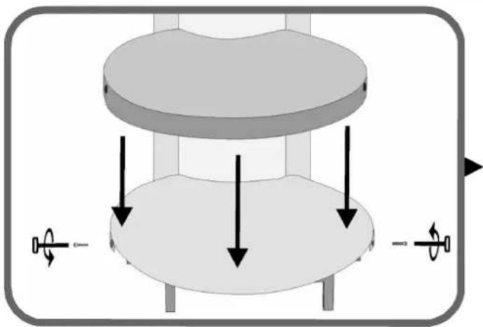
natural_image
3D diagram of a mechanical component with arrows indicating force or motion directions (no text or symbols)GB No position the synthetic hood and attach this on the side with 2 bolts [ M6 x 20 ].
D Bringen Sie dann die Kunststoffhaube an und schrauben Sie diese an der Seite mit 2 Inbusschrauben fest [ M6 x 20 ].
NL Plaats hierna de kunststofkap en schroef deze vast aan de zijkant met 2 inbusboutjes [ M6 x 20 ].
Placez ensuite le bouchon en plastique et vissez-le sur le côté à l'aide de 2 boulons à six pans creux [ M6 x 20 ].
Montare quindi il coperchio in plastica e avvitarlo di lato con 2 viti esagonali a testa concava. [ M6 x 20 ].
E A continuación, coloque la tapa sintética y atornillela al lateral con 2 tornillos de hexágono interior [M6 x 20].
flowchart
graph TD
    A["Air Inlet"] --> B["Reactor"]
    B --> C{Valve}
    C -->|Flow| D["Reactor Chamber"]
    C -->|Flow| E[" fan Array"]
    D --> F["Reactor Column"]
    E --> G[" fan Array"]
    style A fill:#f9f,stroke:#333
    style F fill:#ccf,stroke:#333
    style G fill:#ccf,stroke:#333
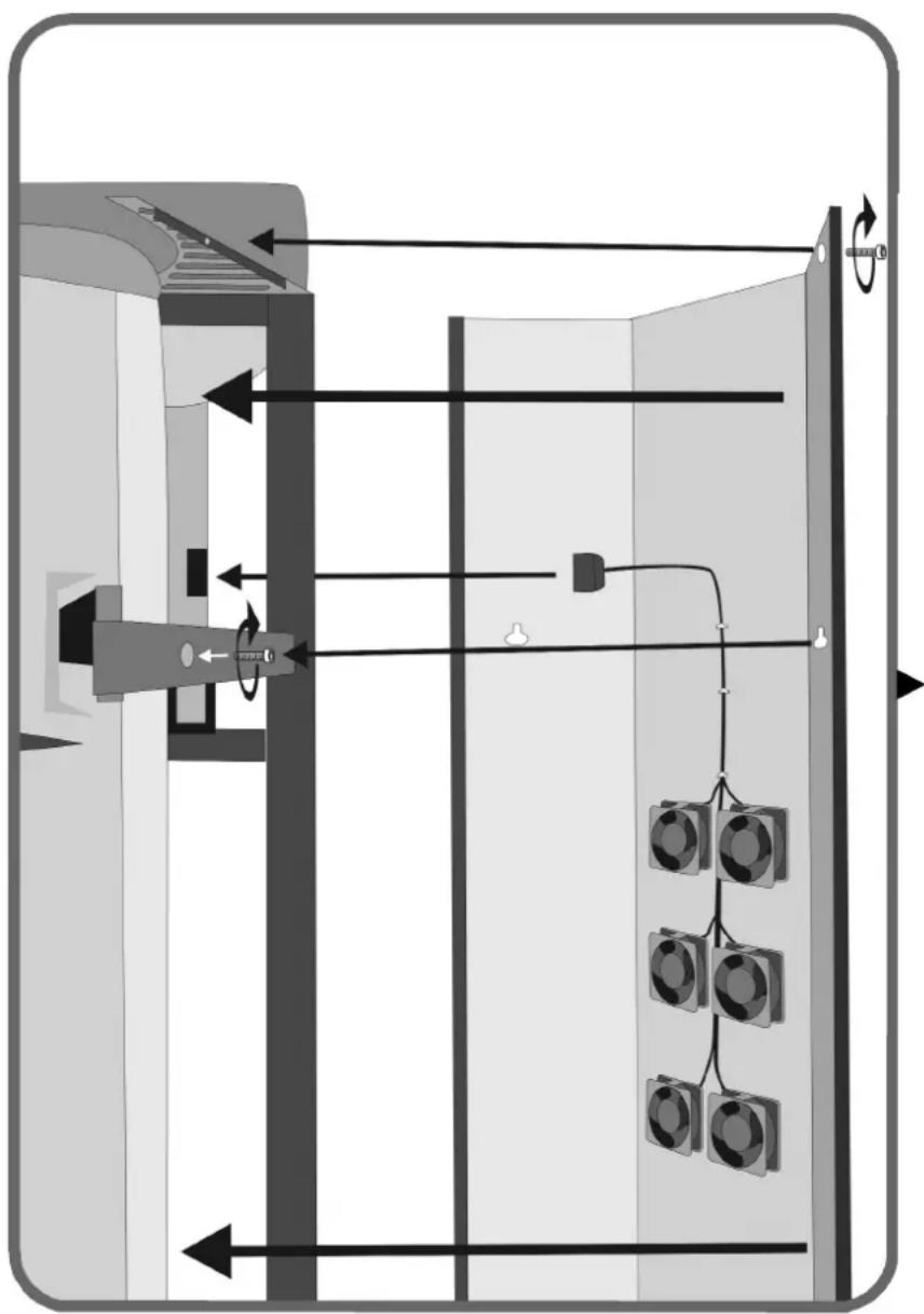
GB
Partially screw the 2 bolts [ M6 x 20 ] into the upper hinge arms. Connect the plug of the rear plate to the electric plate and position the rear plate over the already mounted bolts. Screw 2 bolts [ M6 x 20 ] into the lower hinge arms, 2 bolts [ M6 x 20 ] into the mains filter plate, and 2 bolts [ M6 x 20 ] into the left and right cover plates. Then tighten all bolts.
D
Numbered Wattage of lamps = 48 x 120W
Weight 334 kg
Gross Weight 423 kg
▶ Technical data
▶ Lumina V intensive
Voltage (Fuse) Wattage
400V/3\~N/PE/50Hz 3 x 20A 9,22kW
230V/3\~PE/50Hz 3 x 32A
230V/1\~N/PE/50Hz 1 x 50A
Note!
For UK only!
420V/3\~N/PE/50Hz 3 x 20A 10,1kW
Numbered Wattage of lamps = 48 x 180W
Weight 334 kg
Gross Weight 423 kg
▶Electro and filterplate
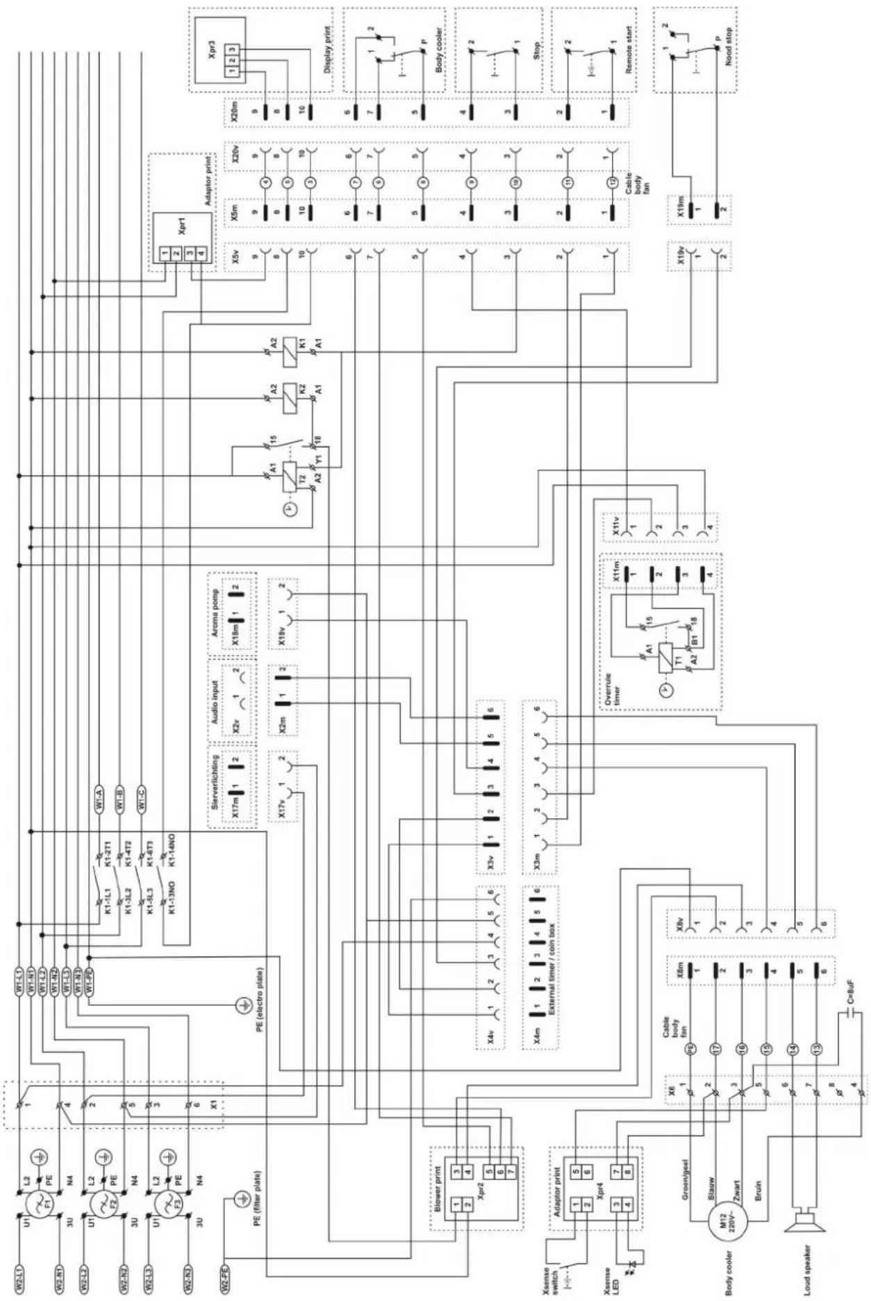
flowchart
graph TD
    subgraph Power Supply
        W2-L1["W2-L1"] --> U1["U1"]
        W2-N1["W2-N1"] --> U2["U2"]
        W2-L2["W2-L2"] --> U3["U3"]
        W2-N2["W2-N2"] --> U4["U4"]
        W2-L3["W2-L3"] --> U5["U5"]
        W2-N3["W2-N3"] --> U6["U6"]
        W2-PD["W2-PD"] --> PE["PE (filter plate)"]
        PE --> BlowerPrint["Blower print"]
        BlowerPrint --> Xpr1["Xpr1"]
        BlowerPrint --> X4v["X4v"]
        BlowerPrint --> X3v["X3v"]
        BlowerPrint --> X4m["X4m"]
        BlowerPrint --> X3m["X3m"]
        BlowerPrint --> X4m["External timer / coin box"]
        BlowerPrint --> X4m["External timer / coin box"]
        BlowerPrint --> X4m["External timer / coin box"]
        BlowerPrint --> X4m["External timer / coin box"]
        BlowerPrint --> X4m["External timer / coin box"]
        BlowerPrint --> X4m["External timer / coin box"]
        BlowerPrint --> X4m["External timer / coin box"]
        BlowerPrint --> X4m["External timer / coin box"]
        BlowerPrint --> X4m["External timer / coin box"]
        BlowerPrint --> X4m["External timer / coin box"]
        BlowerPrint --> X4m["External timer / coin box"]
        BlowerPrint --> X4m["External timer / coin box"]
        BlowerPrint --> X4m["External timer / coin box"]
        BlowerPrint --> X4m["External timer / coin box"]
        Blower_Print["Xaense switch"] --> AdaptorPrint["Adaptor print"]
        AdaptorPrint --> Xpr1
        AdaptorPrint --> X4v
        AdaptorPrint --> X3v
        AdaptorPrint --> X4m
        AdaptorPrint --> X3m
        Adaptor_Print["Xaense LED"] --> AdaptorPrint
        Adaptor_Print["Xaense LED"] --> BlowerPrint
        Blower_Print["Xaense switch"] --> Blower Print
        Blower_Print["Xaense LED"] --> Blower Print
        Blower_Print["Xaense switch"] --> Blower Print
        Blower_Print["Xaense Switch"] --> Blower Print
        Blower_Print["Xaense Switch"] --> Blower Print
        Blower_Print["Xaense Switch"] --> Blower Print
        Blower_Print["Xaense Switch"] --> Blower Print
        Blower_Print["Xaense Switch"] --> Blower Print
        Blower_Print["Xaense Switch"] --> Blower Print
        Blower_Print["Xaense Switch"] --> Blower Print
        Blower_Print["Xaense Switch"] = Body_cooler["M12 220V~ Zwart"]
        Blower_Print["Xaense Switch"] = Body_cooler["M12 220V~ Zwart"]
        Blower_Print["Xaense Switch"] = Body_cooler["M12 220V~ Zwart"]
        Blower_Print["Xaense Switch"] = Body_cooler["M12 220V~ Zwart"]
    end

    subgraph Control Circuit
        W1-L1["W1-L1"] --> K1-1L1["K1-1L1"]
        W1-N1["W1-N1"] --> K1-3L2["K1-3L2"]
        W1-L2["W1-L2"] --> K1-3L3["K1-3L3"]
        W1-L3["W1-L3"] --> K1-3L4["K1-3L4"]
        W1-L4["W1-L4"] --> K1-3L5["K1-3L5"]
        W1-L5["W1-L5"] --> K1-3L6["K1-3L6"]
        W1-L6["W1-L6"] --> K1-3L7["K1-3L7"]
        W1-L7["W1-L7"] --> K1-3L8["K1-3L8"]
        W1-L8["W1-L8"] --> K1-3L9["K1-3L9"]
        W1-L9["W1-L9"] --> K1-3L10["K1-3L10"]
        W1-A["W7-A"] --> K1-3L10
        K1-3L10["K1-3L10"] --> K1-3L2["K1-3L2"]
        K1-3L2["K1-3L2"] --> K1-3L3["K1-3L3"]
        K1-3L3["K1-3L3"] --> K1-3L4["K1-3L4"]
        K1-3L4["K1-3L4"] --> K1-3L5["K1-3L5"]
        K1-3L5["K1-3L5"] --> K1-3L6["K1-3L6"]
        K1-3L6["K1-3L6"] --> K1-3L7["K1-3L7"]
        K1-3L7["K1-3L7"] --> K1-3L8["K1-3L8"]
        K1-3L8["K1-3L8"] --> K1-3L9["K1-3L9"]
    end

    subgraph Control Circuit
        A["A+"] --> B["A2"]
    end

    subgraph Display Circuit
        C["Xpr1"] --> D["Xpr3"]

    subgraph Cable Body Fan
            E["Cable body fan: Overrule timer, T1, A2, B1, X8v, X6, X8v, X6, X4v, X4m, X3m, X2m, X2v, X2v, X4m, X4m, X4m, X4m, X4m, X4m, X4m, X4m, X4m, X4m, X4m, X4m, X4m, X4m, X4m, X4m, X4m, X4m, X4m, X4m, X4m, X4m, X4m, X4m, X4m, X4p<br>    end<br><br>    subgraph Cable Body Fan<br>            E[A+"] --> F["A2"]
    end

    subgraph Cable Body Fan
            F["A2"] --> G["B1"]
    end

    subgraph Cable Body Fan
            G["B1"] --> H["Overrule timer, T1, A2, B1, X8v, X6, X8v, X6, X4v, X4m, X3m, X2m, X2v, X2v, X4m, X4m, X4m, X4m, X4m, X4m, X4m, X4m, X4m, X4m, X4p<br>    end<br><br>    subgraph Cable Body Fan<br>            E[A+"] --> I["A2"]
    end

    subgraph Cable Body Fan
            I["A2"] --> J["B1"]
    end

    subgraph Cable Body Fan
            J["B1"] --> K["A2"]
    end

    subgraph Cable Body Fan
            K["A2"] --> L["A2"]
    end

    subgraph Cable Body Fan
            L["A2"] --> M["A2"]
    end

    subgraph Cable Body Fan
            M["A2"] --> N["A2"]
    end

    subgraph Cable Body Fan
            N["A2"] --> O["A2"]
    end

    subgraph Cable Body Fan
            O["A2"] --> P["A2"]
    end

    subgraph Cable Body Fan
            P["A2"] --> Q["A2"]
    end

    subgraph Cable Body Fan
            Q["A2"] --> R["A2"]
    end

    subgraph Cable Body Fan
            R["A2"] --> S["A2"]
    end

    subgraph Cable Body Fan
            S["A2"] --> T["A2"]
    end

    subgraph Cable Body Fan
            T["A2"] --> U["A2"]
    end

    subgraph Cable Body Fan
            U["A2"] --> V["A2"]
    end

    subgraph Cable Body Fan
            V["A2"] --> W["A2"]
    end

    subgraph Cable Body Fan
            W["A2"] --> X["A2"]
    end

    subgraph Cable Body Fan
            X["A2"] --> Y["A2"]
    end

    subgraph Cable Body Fan
            Y["A2"] --> Z["A2"]
    end

    subgraph Cable Body Fan
            Z["A2"] --> AA["A2"]
    end

    subgraph Cable Body Fan
            AA["A2"] --> AB["A2"]
    end

    subgraph Cable Body Fan
            AB["A2"] --> AC["A2"]
    end

    subgraph Cable Body Fan
            AC["A2"] --> AD["A2"]
    end

    subgraph Cable Body Fan
            AD["A2"] --> AE["A2"]
    end

    subgraph Cable Body Fan
            AE["A2"] --> AF["A2"]
    end

    subgraph Cable Body Fan
            AF["A2"] --> AG["A2"]
    end

    subgraph Cable Body Fan
            AG["A2"] --> AH["A2"]
    end

    subgraph Cable Body Fan
            AH["A2"] --> AI["A2"]
    end

    subgraph Cable Body Fan
            AI["A2"] --> AJ["A2"]
    end

    subgraph Cable Body Fan
            AJ["A2"] --> AK["A2"]
    end

    subgraph Cable Body Fan
            AK["A2"] --> AL["A2"]
    end

    subgraph Cable Body Fan
            AL["A2"] --> AM["A2"]
    end

    subgraph Cable Body Fan
            AM["A2"] --> ANA["A2"]
    end

    subgraph Cable Body Fan
            ANA["A2"] --> AO["Overrule timer, T1, A2, B1, X8v, X6, X8v, X6, X8v, X6, X8v, X6, X8v, X6, X8v, X6, X8v, X6, X8p<br>    end<br><br>    subgraph Cable Body Fan<br>            O[Overrule timer, T1, A2, B1, X8v, X6, X8v, X6, X8v, X6, X8v, X6, X8v, X6, X8v, X6, X8p<br>    end<br><br>    subgraph Cable Body Fan<br>            O[Overrule timer, T1, A2, B1, X8v, X6, X8v, X6, X8v, X6, X8v, x8p<br>    end<br><br>    subgraph Cable Body Fan<br>            O[Overrule timer, T1, A2, B1, x8v, x6, x8v, x6, x8v, x6, x8v, x6, x8v, x6, x8p<br>    end<br><br>    subgraph Cable Body Fan<br>            O[Overrule timer, T1, A2, B1, x8v, x6, x8v, x6, x8v, x6, x8v, x6, x8p<br>    end<br><br>    subgraph Cable Body Fan<br>            O[Overrule timer, T1, A2, B1, x8v, x6, x8v, x6, x8v, x6, x8v, x6, x8p<br>    end<br><br>    subgraph Cable System Input<br>            P[Xpr1"] --> Q["Xpr3"]

    subgraph Cable System Input
            Q["Xpr3"]

    end
Electrical diagrams leftdoor
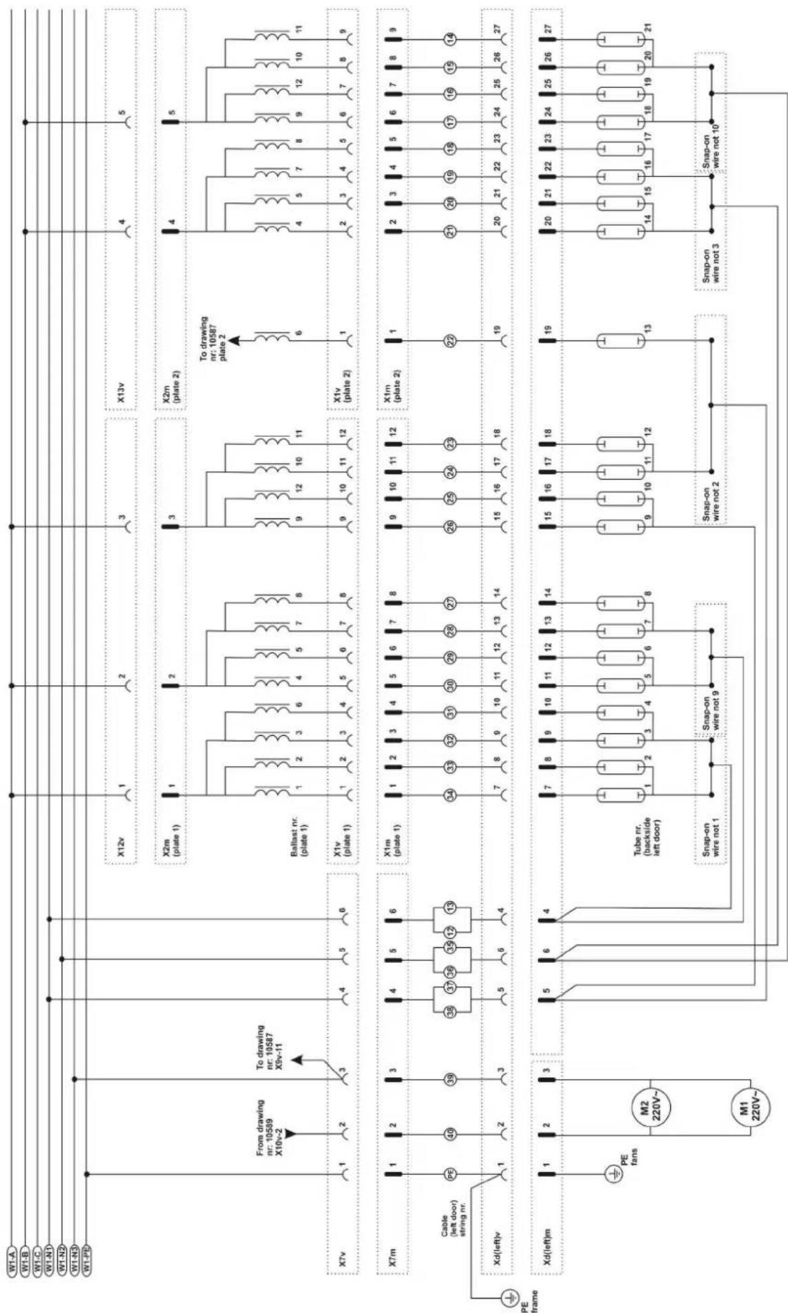
flowchart
graph TD
    subgraph Power Source
        W1A["W1.A"]
        W1B["W1.B"]
        W1C["W1.C"]
        W1D["W1.N1"]
        W1E["W1.N2"]
        W1F["W1.N3"]
        W1G["W1.PD"]
    end

    subgraph Power Equipment
        XTV["XTv"]
        Xm["XTm"]
        Xd["dX(d)(left)v"]
        XdLeftm["Xd(left)m"]
    end

    subgraph Cable & Cable Line
        Pe["PE"] --> PE_fans["PE fans"]
        Pe --> M2["M2 220V~"]
        Pe --> M1["M1 220V~"]
    end

    subgraph Power Supply
        X12v["X12v"] --> 1["1"]
        X2m["X2m (plate 1)"] --> 1["1"]
        Ballast["Ballast nr. (plate 1)"] --> 1["1"]
        X1v["X1v (plate 1)"] --> 1["1"]
        X1m["X1m (plate 1)"] --> 1["1"]
        XdLeftm --> 1["1"]
        XdLeftm --> 5["5"]
        XdLeftm --> 6["6"]
        XdLeftm --> 4["4"]
    end

    subgraph Power Supply
        X13v["X13v"] --> 4["4"]
        X2m["X2m (plate 2)"] --> 4["4"]
        Ballast --> 9["9"]
        Ballast --> 10["10"]
        Ballast --> 8["8"]
        X1v --> 9["9"]
        X1v --> 10["10"]
        X1v --> 11["11"]
        X1m --> 9["9"]
        X1m --> 10["10"]
        X1m --> 11["11"]
        XdLeftm --> 7["7"]
        XdLeftm --> 8["8"]
        XdLeftm --> 9["9"]
        XdLeftm --> 10["10"]
        XdLeftm --> 11["11"]
        XdLeftm --> 12["12"]
        XdLeftm --> 13["13"]
    end

    subgraph Power Supply
        X2m --> 6["6"]
        X2m --> 4["4"]
        Ballast --> 9
        Ballast --> 8
        X1v --> 6
        X1v --> 4
        X2m --> 6
        X2m --> 4
        Ballast --> 9
        Ballast --> 8
        X1m --> 6
        X1m --> 4
        Ballast --> 8
        XdLeftm --> 7
        XdLeftm --> 8
        XdLeftm --> 9
        XdLeftm --> 10
        XdLeftm --> 11
        XdLeftm --> 12
        XdLeftm --> 13
    end

    subgraph Power Supply
        X2m --> ToDrawing["XTo drawing nr. 10587 plate 2"]
        X2m --> ToDrawing2["XTo drawing nr. 10587 plate 2"]
    end

    subgraph Cable & Cable Line
        Pe --> PE_fans
        Pe --> M2_M2_220V~
        Pe --> M1_M1_220V~
    end

    subgraph Power Supply
        X12v --> ToDrawing
        X2m --> ToDrawing
    end

    subgraph Power Supply
        X2m --> ToDrawing2
    end

    style Power Supply fill:#f9f,stroke:#333,stroke-width:2px
    style Cable & Cable Line fill:#ccf,stroke:#333,stroke-width:2px
Electrical diagrams rightdoor
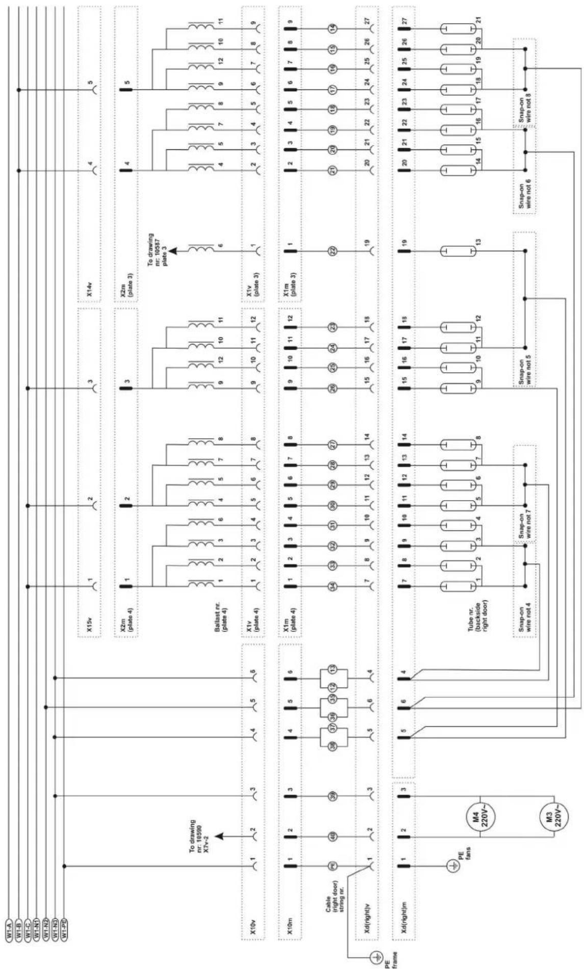
flowchart
graph TD
    subgraph Power Line
        W1A["W1-A"] --> X15v["X15v"]
        W1B["W1-B"] --> X15v
        W1C["W1-C"] --> X15v
        W1N1["W1-N1"] --> X15v
        W1N2["W1-N2"] --> X15v
        W1N3["W1-N3"] --> X15v
        W1PB["W1-PB"] --> X15v
    end

    subgraph Power Line
        X10v["X10v"] --> X2m["X2m (plate 4)"]
        X10v --> X2m
        X10v --> X2m
        X10v --> X2m
        X10v --> X2m
        X10v --> X2m
        X10v --> X2m
        X10v --> X2m
        X10v --> X2m
        X10v --> X2m
        X10v --> X2m
        X10v --> X2m

    end

    subgraph Power Line
        X10m["X10m"] --> X1m["X1m (plate 4)"]
        X10m --> X1m
        X10m --> X1m
        X10m --> X1m
        X10m --> X1m
        X10m --> X1m
        X10m --> X1m
        X10m --> X1m
        X10m --> X1m

    end

    subgraph Power Line
        Xd["Xd(right)v"] --> PE["PE frame"]
        PE --> Cable["Cable (right door) string nr."]
        Cable --> PE_fans["PE fans"]
        PE_fans --> M4["M4 220V~"]
        PE_fans --> M3["M3 220V~"]

    end

    subgraph Power Line
        XdRight["Xd(right)m"] --> Tube["Tube nr. (backside right door)"]
        Tube --> Snap-on["Snap-on wire not 4"]
        Tube --> Snap-onWire7["Snap-on wire not 7"]

    end

    subgraph Power Line
        XdRight["Xd(right)m"] --> Snap-onS["nap-on wire not 5"]
        Snap-onS --> Snap-onWire6["Snap-on wire not 6"]
        Snap-onWire8["Snap-on wire not 8"]

    end

    subgraph Power Line
        XdRight["Xd(right)m"] --> CableLeft[" Cable (right door) string nr. "]
        CableLeft --> CableRight[" Cable (right door) string nr. "]
        CableRight --> CableRightLeft[" Cable (right door) string nr. "]
        CableRightLeft --> CableRightRight[" Cable (right door) string nr. "]
        CableRightRight[" Cable (right door) string nr. "]
        CableRightRightLeft[" Cable (right door) string nr. "]
        CableRightRightRight[" Cable (right door) string nr. "]

    end

    subgraph Power Line
        XdRight["Xd(right)m"] --> CableLeft[" Cable (right door) string nr. "]
        CableLeft --> CableRight[" Cable (right door) string nr. "]
        CableRight[" Cable (right door) string nr. "]
        CableRightRight[" Cable (right door) string nr. "]

    end

    subgraph Power Line
        XdRight["Xd(right)m"] --> CableLeft[" Cable (right door) string nr. "]
        CableLeft --> CableRight[" Cable (right door) string nr. "]
        CableRight[" Cable (right door) string nr. "]

    end

    subgraph Power Line
        XdRight["Xd(right)m"] --> CableLeft[" Cable (right door) string nr. "]
        CableLeft --> CableRight[" Cable (right door) string nr. "]
        CableRight[" Cable (right door) string nr. "]

    end

    subgraph Power Line
        XdRight["Xd(right)m"] --> CableLeft[" Cable (right door) stringnr. "]
        CableLeft --> CableRight[" Cable (right door) stringnr. "]

    end

    subgraph Power Line
        XdRight["Xd(right)m"] --> CableLeft[" Cable (right door) stringnr. "]
        CableLeft --> CableRight[" Cable (right door) stringnr. "]

    end

    subgraph Power Line
        XdRight["Xd(right)m"] --> CableLeft[" Cable (right door) stringnr. "]
        CableLeft --> CableRight[" Cable (right door) stringnr. "]

    end


    subgraph Power Line
        XdRight["Xd(right)m"] --> CableLeft[" Cable (right door) stringnr. "]
        CableLeft --> CableRight[" Cable (right door) stringnr. "]

    end

    subgraph Power Line
        XdRight["Xd(right)m"] --> CableLeft[" Cable (right door) stringnr. "]
        CableLeft --> CableRight[" Cable (right door) stringnr. "]

    end

    subgraph Power Line
Electrical diagrams column
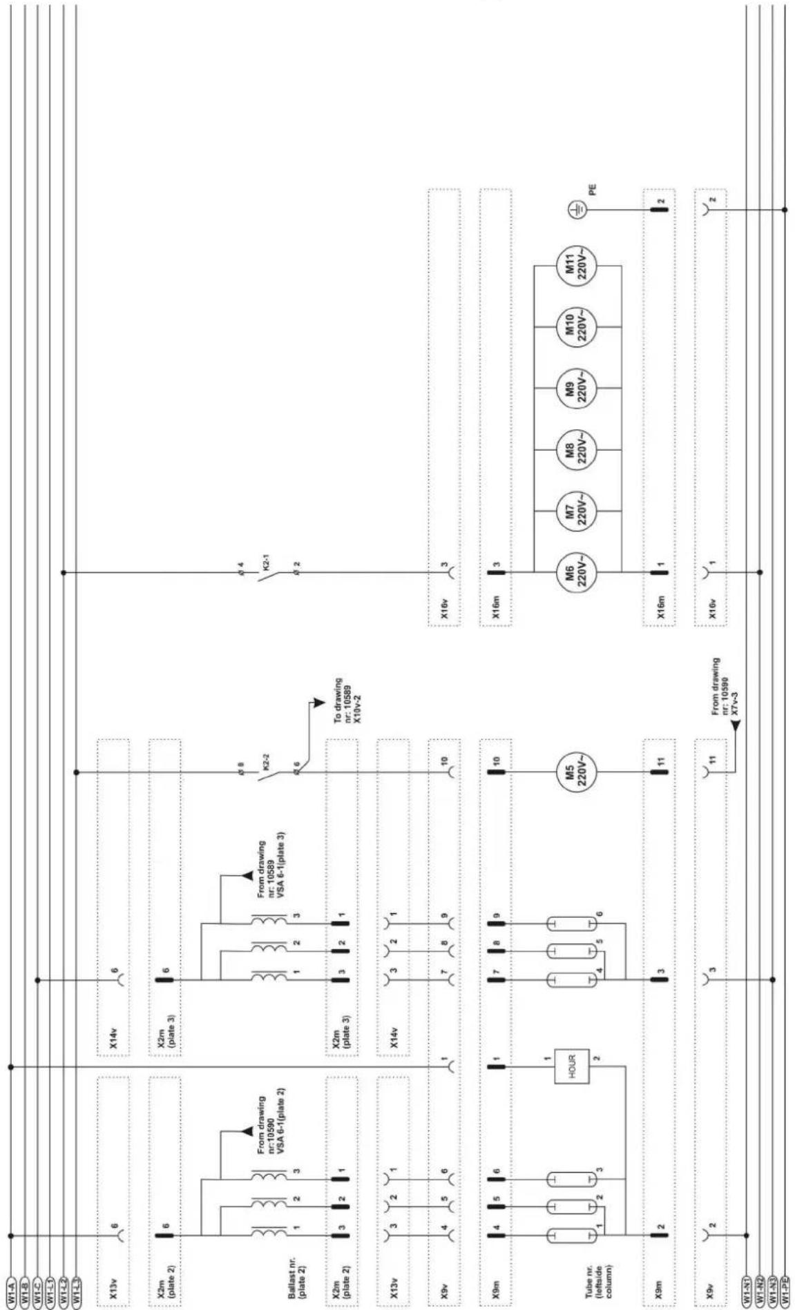
text_image
W1-A W1-B W1-C W1-D W1-E X13v 6 X2m (plate 2) 6 Ballast nr. (plate 2) 1 2 3 From drawing nr:10590 VSA 6-1(plate 2) X2m (plate 2) 3 2 1 X13v 3 2 1 X9v 4 5 6 X9m 4 5 6 Tube nr. (leftside column) 1 2 3 HOUR 2 X9m 2 X9v 2 W1-N1 W1-N2 W1-N3 W1-PD X14v 6 X2m (plate 3) 6 From drawing nr: 10589 VSA 6-1(plate 3) X2m (plate 3) 3 2 1 X14v 3 2 1 7 8 9 To drawing nr: 10589 X10v-2 K2-2 K2-1 6 8 To drawing nr: 10589 X10v-2 10 X16v 3 X16m 3 M6 220V~ M7 220V~ M8 220V~ M9 220V~ M10 220V~ M11 220V~ PE X16m 1 X16v 1 From drawing nr: 10590 X7v-3Electrical diagrams capacitors
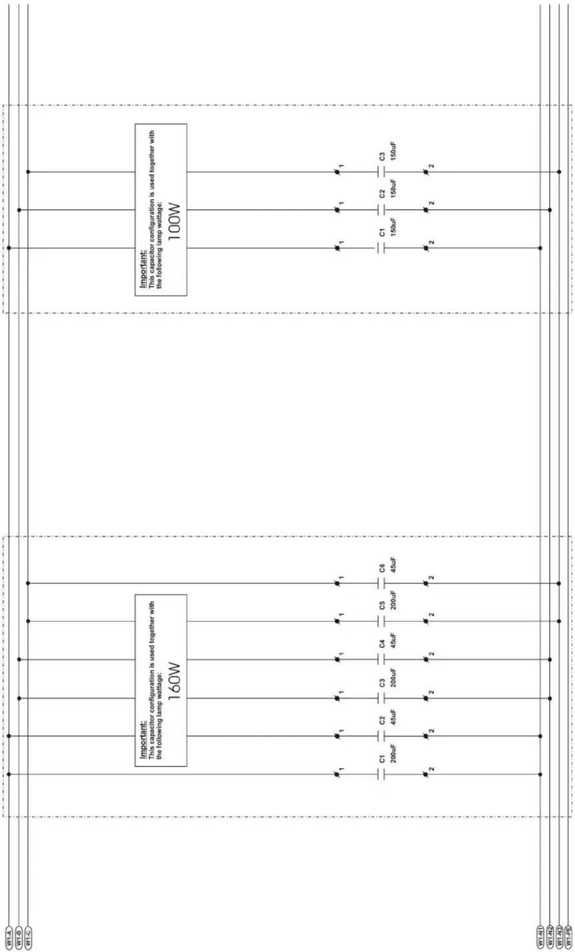
text_image
W1-A W1-B W1-C Important: This capacitor configuration is used together with the following lamp wattage: 160W Important: This capacitor configuration is used together with the following lamp wattage: 100W C1 200uF C2 45uF C3 200uF C4 45uF C5 200uF C6 45uF C1 150uF C2 150uF C3 150uF W1-N1 W1-N2 W1-N3 W1-PR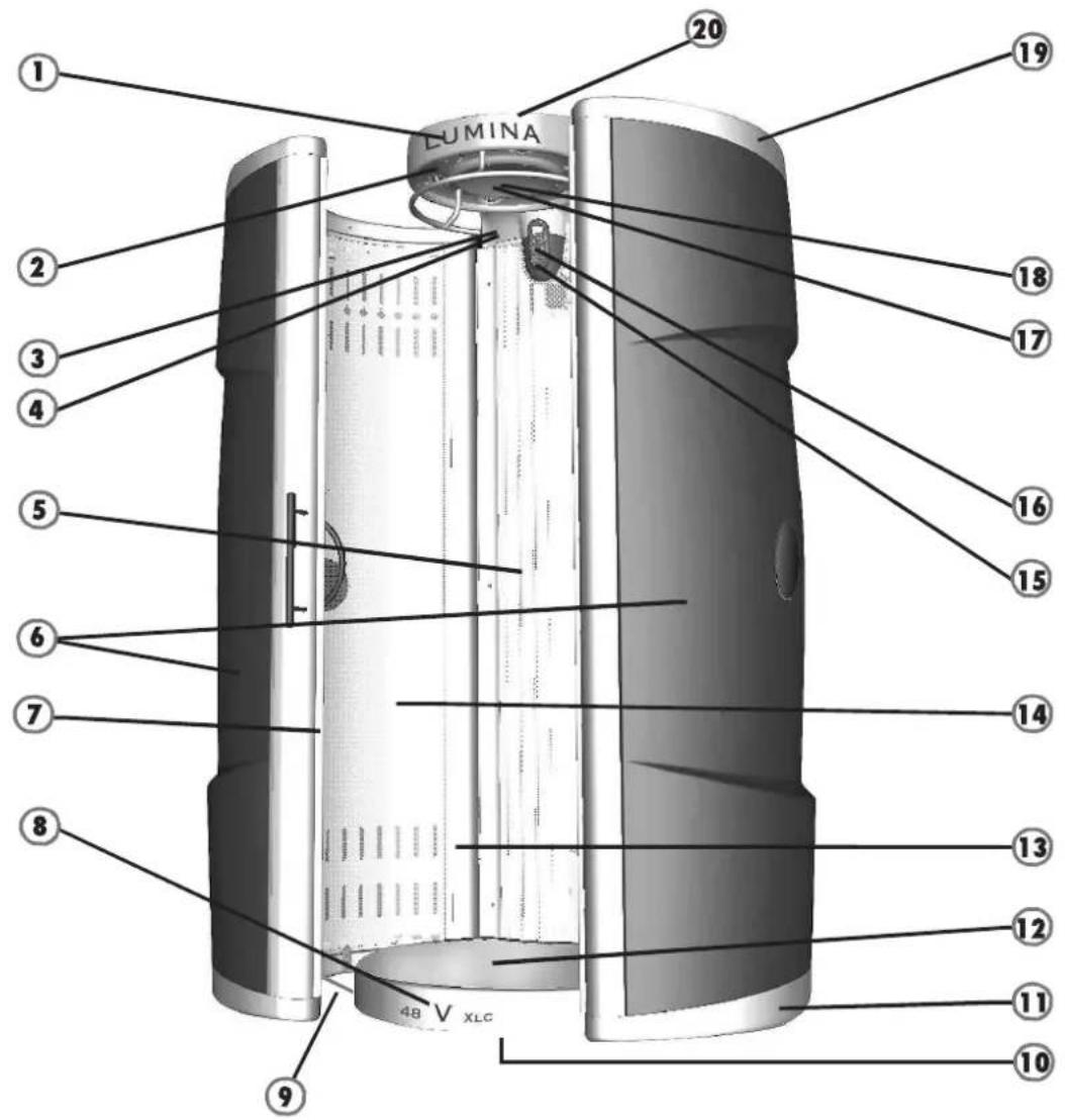
text_image
LUMINA 1 2 3 4 5 6 7 8 9 20 19 18 17 16 15 14 13 12 11 10Artikel nummer
Article number


-
Sticker Lumina 11835
-
Air diffuser 11049
-
Sticker Xsens button 10265
-
Button with LED Xsens 10382
-
Acrylicsheet panel "frosted" 09968
-
Plastic Cover for door Orange 11355
Plastic Cover for door Meteorblack 11120
Plastic Cover for door Midnightblue 11119
Plastic Cover for door Warmsilver 11118
-
Door-rubber 10257
-
Sticker 48V XLC-Intensive 10649
-
Rod 10305
-
Showlight floor (optional) "Tld" 10605
-
Endcover 11058
-
Cover for floor 09953
-
Aluminium side profile 09963
-
Acrylicsheet door "frosted" 09974
-
Switch (start) 01212
Switch (fan) 10547
Switch (stop) 01207
natural_image
Technical line drawing of a mechanical bracket component (no text or symbols)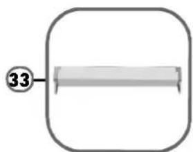
natural_image
Simple diagram of a rectangular frame with a central horizontal bar and a circled number 33 at the top (no text or symbols beyond the number)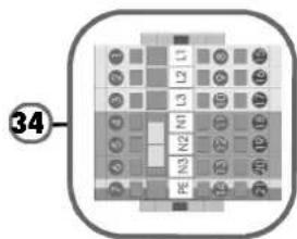
text_image
34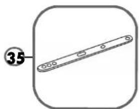
natural_image
Simple line drawing of a mechanical part with a numbered circle (35) pointing to it, enclosed in a rounded square frame (no text or symbols)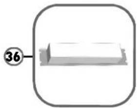
natural_image
Simple 3D diagram of a rectangular object with a circular label containing the number 36, no text or symbols present.
natural_image
Illustration of a threaded screw with a base, no text or symbols present
natural_image
Simple line drawing of a cylindrical electronic component with pins, no text or symbols present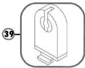
natural_image
Technical line drawing of a mechanical component with a numbered label (39) and no visible text or symbols.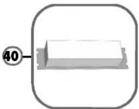
natural_image
Simple 3D diagram of a rectangular object with a circular label '40' pointing to its top face, enclosed in a rounded square frame (no text or symbols on the object itself)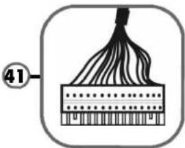
natural_image
Diagram of a fiber optic cable with labeled section 41 (no text or symbols on the diagram itself)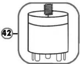
natural_image
Simple line drawing of a cylindrical electronic component with pins, no text or symbols present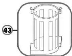
natural_image
Simple line drawing of a cylindrical trash bin with side supports and a numbered label (43) on the left side.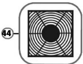
natural_image
Circular pattern with concentric rings and a central black circle, enclosed in a rounded square (no text or symbols)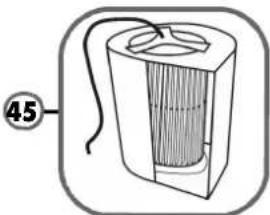
natural_image
Diagram of a cylindrical device with internal structure and labeled part 45 (no text or symbols on the device itself)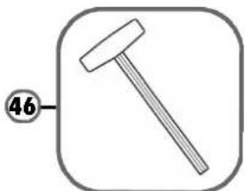
natural_image
Simple line drawing of a hammer inside a rounded square frame (no text or symbols)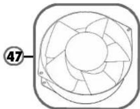
natural_image
Technical line drawing of a mechanical fan or impeller assembly (no text or symbols)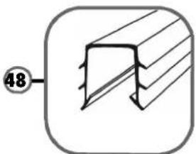
natural_image
Pure technical diagram of a structural component with diagonal hatching and a circled number 48, no text or symbols present.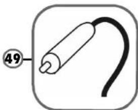
natural_image
Simple line drawing of a medical device with a curved cable and labeled point 49 (no text or symbols beyond the number)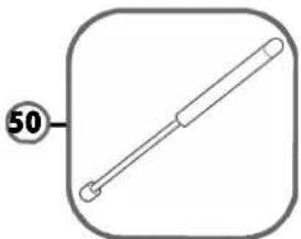
natural_image
Simple line drawing of a rod with a circular label containing the number 50, enclosed in a rounded square frame (no text or symbols on the object itself)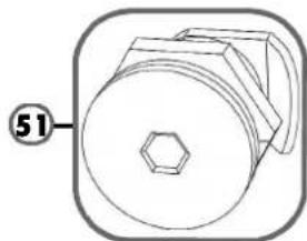
natural_image
Technical drawing of a mechanical component with a hexagonal nut and circular housing (no text or symbols)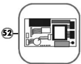
natural_image
Diagram of a computer monitor layout with labeled component (no text or symbols beyond label)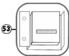
natural_image
Simple line drawing of a rectangular device with mounting holes and a central display (no text or symbols)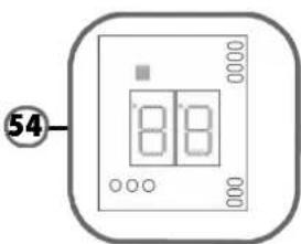
text_image
54 8 8
natural_image
Simple line drawing of a helmet with a circular frame and a numbered label (55) pointing to the helmet area.Article number
Artikel nummer