
W 150 - Paint spray WAGNER - Free user manual and instructions
Find the device manual for free W 150 WAGNER in PDF.


| Product Type | Low-pressure electric spray gun |
| Brand | Wagner |
| Model | W 150 |
| Weight | 1.2 kg |
| Power supply | 230 V ~ 50 Hz |
| Power consumption | 300 W |
| Spraying power | 70 W |
| Maximum product flow rate | 140 ml/min |
| Maximum viscosity | 100 DIN-s |
| Sound pressure level (uncertainty 4 dB(A)) | 75 dB(A) |
| Weighted sound level (uncertainty 4 dB(A)) | 86 dB(A) |
| Vibration level (uncertainty 1.5 m/s²) | < 2.5 m/s² |
| Protection class | I |
| Tank capacity | 600 ml |
| Adjustable spray patterns | Horizontal flat jet, vertical flat jet, round jet |
| Applicable products | Stains, solvent-based or water-based paints, primers |
| Maintenance | Regular cleaning of nozzle, air cap, and air filter; replace diaphragm if necessary |
| Safety | Do not use in explosive atmosphere; wear respiratory protection; do not point at people or animals; unplug before maintenance |
| Spare parts available | Yes, complete list in the manual |
| Warranty | 3 years + 1 additional year with online registration |
Frequently Asked Questions - W 150 WAGNER
User questions about W 150 WAGNER
0 question about this device. Answer the ones you know or ask your own.
Ask a new question about this device
Download the instructions for your Paint spray in PDF format for free! Find your manual W 150 - WAGNER and take your electronic device back in hand. On this page are published all the documents necessary for the use of your device. W 150 by WAGNER.
USER MANUAL W 150 WAGNER
natural_image
Line drawing of a spray gun with control panel and handle (no text or symbols)WOOD & METAL SPRAYER
W 150
ORIGINAL-
BETRIEBSANLEITUNG

natural_image
Illustration of a hand cleaning or adjusting a mechanical component with a numbered label (8) in the top left corner.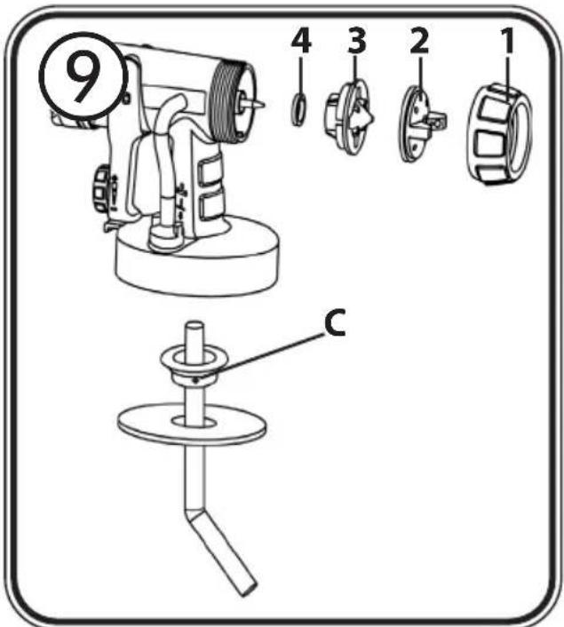
DE 1 - 14
EN 15 - 28
FR 29 - 42
NL 43 - 56
+ +

Fragen? · Questions? · Des questions? · Vragen?

HERZLICHEN DANK FÜR IHR VERTRAUEN
natural_image
Diagram of a mechanical device with a lever and curved arrow indicating rotation (no text or symbols)natural_image
Diagram of a mechanical device with a lever and base, showing rotational motion (no text or symbols)https://go.wagner-group.com/hf-warranty-conditions

Translation of the original operating instructions
MANY THANKS FOR PLACING YOUR TRUST IN US
We would like to congratulate you on purchasing this brand product from Wagner; we are sure that you will enjoy working with it greatly.
Please read the Operating Manual carefully and observe the safety information before starting the device. Store the Operating Manual in a safe place close to the product in case it needs to be used by someone else.
We would be happy to be of assistance if you have any questions, suggestions or requests.
Please contact us via the phone number included on the back page or via our homepage,
www.wagner-group.com/service.
Contents
- Explanation of symbols used .... 16
- General Safety Instructions .... 16
- Safety Instructions for Spray Guns 18
- Description/ Scope of delivery 19
- Coating Materials....20
- Start-up 20
- Adjusting the desired Spray Setting 21
- Adjusting the Material Volume (Fig. 6)....21
- Spray Technique 21
- Interruption of Work till 4 Hours....22
- Taking Out of Operation and Cleaning....22
- Maintenance 23
- Spare Parts List .... 24
- Accessories....24
- Correction of Malfunctions....24
- Technical Data.... 25
- Environmental protection.... 26
- Important Note regarding Product Liability! 26
1. Explanation of symbols used
 | This symbol indicates a potential danger for you or for the device. Under this symbol you can find important information on how to avoid injuries and damage to the device. |
 | Danger of electrical shock |
 | Indicates tips for use and other particularly useful information. |
2. General Safety Instructions
Caution!

Read all safety warnings and all instructions. Failure to follow the warnings and instructions may result in electric shock, fire and/or serious injury. Save all warnings and instructions for future reference.
The term "power tool" in the warnings refer to your mains-operated (corded) power tool or battery-operated (cordless) power tool.
1. Safety at the workplace
a) Keep your workplace clean and well lit. Disorder or unlit workplaces may result in accidents.
b) Never use the tool in hazardous areas that contain flammable liquids, gases or dusts. Power tools generate sparks that can ignite the dust or vapors.
c) Keep children and other persons away when using the power tool. You can lose control of the tool if you are distracted.
2. Electrical Safety
a) The tool plug must fit into the socket. The plug may not be modified in any form. Do not use adaptor plugs together with protective-earthed tools. Unmodified plugs and suitable sockets reduce the risk of an electric shock.
b) Avoid physical contact with earthed surfaces such as pipes, heating elements, stoves and refrigerators. The risk through electric shock increases if your body is earthed.
c) Keep the equipment away from rain and moisture. The risk of an electric shock increases if water penetrates electrical equipment.
d) Do not misuse the mains lead by carrying the tool by the lead, hanging it from
the lead or by pulling on the lead to remove the plug. Keep the lead away from heat, oil, sharp edges or moving tool parts. Damaged or twisted leads increase the risk of an electric shock.
e) If you work outdoors with a power tool, only use extension cables suitable for outdoor use. The use of an extension lead that is suitable for outdoors reduces the risk of an electric shock.
f) If you cannot avoid using the tool in a damp environment, use a residual current operated circuit-breaker. Using a residual current operated circuit-breaker avoids the risk of electric shock.
3. Safety of Persons
a) Be attentive. Pay attention to what you are doing and work sensibly with a power tool. Do not use the tool if you are tired or under the influence of drugs, alcohol or medication. Just a moment of inattentiveness while using the tool can lead to serious injuries.
b) Wear personal safety equipment and always wear safety goggles Wearing personal protective equipment, such as dust mask, non-slip safety shoes, safety helm or ear protection, depending on the type of power tools, reduces the risk of injury.
c) Avoid accidental starting-up. Make sure that the electric tool is switched off before you connect it to the power supply, pick it up or carry it. Accidents can occur if you carry the power tool while your finger is on the switch or if you connect the power tool to the power supply which it is on.
d) Remove setting tools or wrenches before switching on the power tool. A tool or wrench that is in a rotating tool part can lead to injuries.
e) Avoid an unnatural posture. Ensure that you are standing securely and have your balance at all times. This ensures that you can control the tool better in unexpected situations.
f) Wear suitable clothing. Do not wear wide clothing or jewellery. Keep your hair, clothes and gloves away from moving parts. Loose clothing, jewellery or long hair can be caught in moving parts.
g) Do not lull yourself into a false sense of security and do not think yourself above the safety rules for electric tools, even if you are familiar with the electric tool following extensive practical experience. Careless use can lead to serious injuries in fractions of a second.
4. Usage and treatment of the electric tool
a) Do not overload the tool. Use the power tool designed for the work that you
are doing. You work better and safer in the specified performance range if you use the suitable power tool.
b) Do not use power tools whose switch is defective. A power tool that cannot be switched on or off is dangerous and has to be repaired.
c) Remove the plug from the socket before carrying out tool settings, changing accessories or putting the tool away. This precautionary measure prevents unintentional starting of the tool.
d) Store unused power tools so that they are inaccessible to children. Do not let persons use the tool who are not familiar with it or who have not read these instructions. Power tools are dangerous when they are used by inexperienced persons.
e) Take proper care of your tools. Check whether the moving parts functiontrouble-free and do not jam, whether parts are broken or damaged so that the tool function is impaired. Have damaged parts repaired before using the tool. Many accidents have their origin in power tools that have been maintained badly.
f) Use the power tool, accessories, insert tools, etc. in accordance with these instructions and in a fashion specified for this special tool type. Take the working conditions and the activity to be carried out into consideration. The use of power tools for purposes other than the intended ones can lead to dangerous situations.
g) Keep the handles and grip surfaces dry, clean and free of oil and grease. Slippery handles and grip surfaces hamper safe operation and control of the electric tool in unforeseen situations.
5. Service
a) Have your tool repaired only by qualified specialist personnel and only with original spare parts. This ensures that the tool safety is maintained.
b) If the supply cord is damaged, it must be replaced by the manufacturer or it's service agent or a similarly qualified person in order to avoid a safety hazard.
3. Safety Instructions for Spray Guns
- The device may not be used in workplaces covered by the explosion-protection regulations.
- There must be no sources of ignition such as, for example, open fires, smoke of lit cigarettes, cigars and tobacco pipes, sparks, glowing wires, hot surfaces, etc. in the vicinity during spraying.
- Do not spray any substances whose hazard potential is not known.
- Before working on the spray gun remove the power plug from the socket.
- Do not use the spray guns to spray flammable substances.
-
The spray guns are not to be cleaned with flammable solvents.
-
Caution against dangers that can arise from the sprayed substance and observe the text and information on the containers or the specifications given by the substance manufacturer.
- Caution! Wear breathing equipment: Paint mist and solvent vapors are damaging to health. Always wear breathing equipment and only work in well ventilated rooms or using supplementary ventilating equipment. It is advisable to wear working clothing, safety glasses, ear protection and gloves.

CAUTION: DANGER OF INJURY!
Never point the spray stream towards human beings or animals.

Sockets and plugs must be masked. Risk of an electric shock as a consequence of sprayed material entering the socket!

Attention! Never operate the device if the nozzle seal is either damaged or missing. If the nozzle seal is either missing or damaged liquids can enter the device and increase the risk of an electric shock. Check the nozzle seal before each use.
- When working with the W 150 indoors as well as outdoors ensure that no solvent vapors are sucked in by the spray gun.
- When working outdoors, be aware of the wind direction. Wind can carry the coating substance across greater distances - thus causing damage. When working indoors, provide for adequate ventilation.
- Do not let children handle the device.
- Never open the device yourself in order to carry out repairs in the electrical system!

The units may only be used with a functional valve. If paints rises in the ventilating hose (Fig. 1, item 15) do not operate the unit further! Dismantle and clean the ventilating hose, valve and diaphragm and replace the diaphragm if necessary.
- Do not lay the spray gun.
With original WAGNER accessories and spare parts, you have the guarantee that all safety regulations are fulfilled.
4. Description/ Scope of delivery
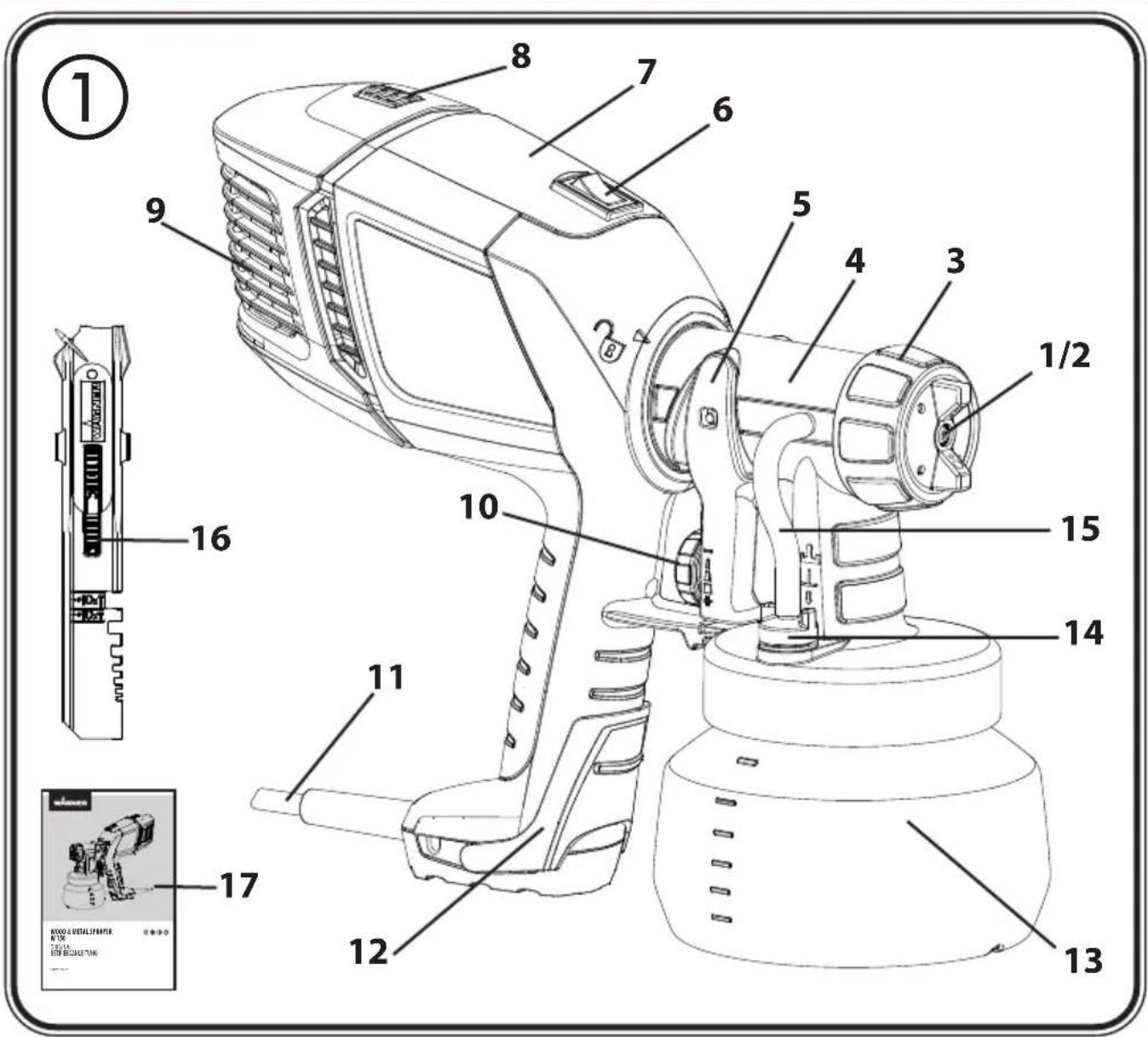
| Description/ Scope of delivery (Fig. 1) | |
| 1) Air Cap 2) Nozzle | |
| 3) Union nut 4) Standard small spray attachment | |
| 5) Trigger 6) ON/OFF switch | |
| 7) Spray gun rear part 8) Locking of the air filter cover | |
| 9) Air filter cover 10) Material volume adjustment | |
| 11) Mains lead 12) Fold-out handle extension | |
| 13) Container 14) Valve | |
| 15) Ventilating hose 16) Stir stick | |
Description/ Scope of delivery (Fig. 1)
| 17) Operating instructions 18) Replacement | nozzle seal* |
| 19) Lubricating grease* |
* This is inside the container: remove it before starting operations!
5. Coating Materials
| Coating Materials Suitable for Use | |
| Glazes, Wood preservatives undiluted | |
| Paints containing solvents and water-soluble paints, primers dilute by 5 - 10% | |
Coating Materials Not Suitable for Use
| Wall paints, materials that contain highly abrasive components, facade paint, caustic solutions and acidic coating substances. Flammable materials. |
Paints, varnishes and glazes can be sprayed undiluted or slightly diluted.
- Stir the material up and put the required amount into the paint container.
- If the convey capacity is too low, add 5 - 10% dilution step-by-step until the convey capacity fulfils your requirements.
6. Start-up
Before connecting to the mains supply, be sure that the supply voltage is identical with the value given on the rating plate.
- Unscrew the container from the spray gun.
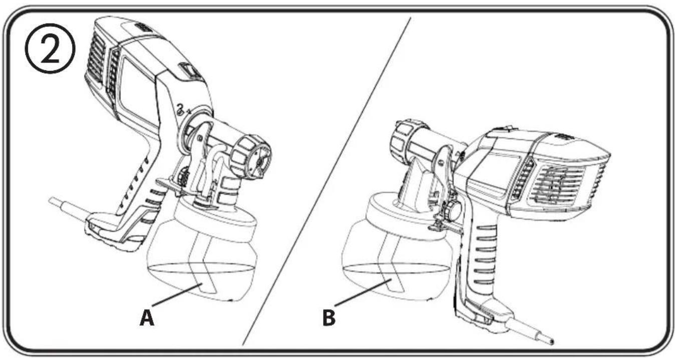
• Aligning suction tube. (Fig. 2)
If the suction tube is positioned correctly, the container contents can be sprayed without almost any residue.
When working on lying objects: Turn the suction tube forwards. (Fig. 2 A)
Spraying work when working on overhead objects: Turn the suction tube rearwards. (Fig. 2 B)
- Set the container on a sheet of paper, pour in the prepared coating material and screw the container tightly onto the spray gun.
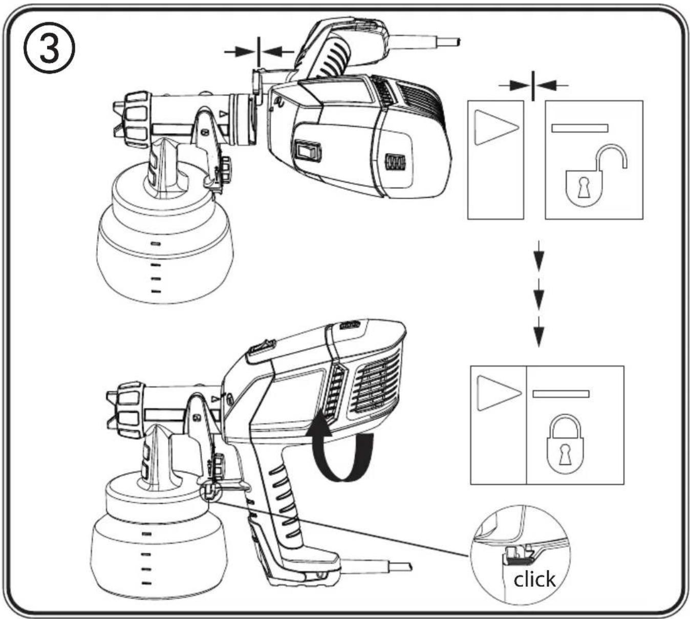
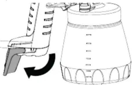
- Connect the front part with the rear part of the gun (Fig. 3).

A selection of spray attachments with different container heights are available as accessories. Always fold out the handle extension before placing on the ground if you are using a different spray attachment to the included Standard small spray attachment to balance the container height.
natural_image
Diagram of a mechanical device with a lever and curved arrow indicating rotation (no text or symbols)- Put the machine down only on a level, clean surface. Otherwise the machine could tip over!

Always switch the W 150 on first before pulling the trigger. Otherwise, there will be a delay in the turbine starting up and the material may drip unatomised from the nozzle.
- Switch the unit on using the ON/OFF switch (Pos. I).
- Pull the trigger.
- Adjust the spray setting on the spray gun.
7. Adjusting the desired Spray Setting
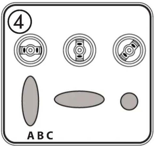
Three different spray jet settings can be chosen on the spray gun, depending on the application and target object.

WARNING! Danger of injury! Never pull the trigger guard while adjusting the air cap.
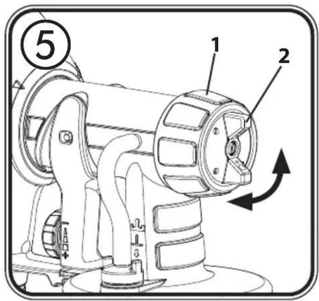
With the union nut (fig. 5, 1) slightly unscrewed, turn the air cap (2) to the desired spray setting position (arrow). Then tighten the union nut.
Fig. 4 A = vertical flat jet → for horizontal surfaces
Fig. 4 B = horizontal flat jet → for vertical surfaces
Fig. 4 C = circular jet → for corners, edges and hard-to-reach surfaces
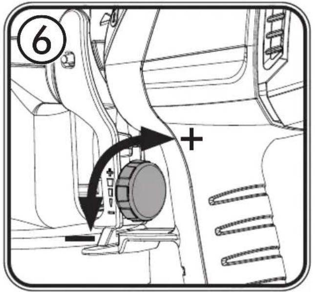
8. Adjusting the Material Volume (Fig. 6)
Set the material volume by turning the regulator on the trigger guard of the spray gun.
- turn to the left → lower material volume
+ turn to the right → higher material volume
9. Spray Technique
- The spray result depends heavily on the smoothness and cleanliness of the surface to be sprayed. Therefore the surface should be carefully prepared and kept free of dust.
- Cover all surfaces not to be sprayed.
- Cover screw threads or similar parts of the target object.
- It is advisable to test the spray gun on cardboard or a similar surface to find the correct setting.
Important: Begin spraying outside of the target area and avoid interruptions inside the target area.
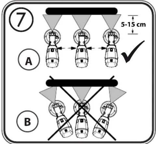
- Correct (Fig. 7a) Be sure to hold the spray gun at an even distance of approx. 5 - 15 cm to the target object.
- Incorrect (Fig. 7b) Heavy spray fog build-up, uneven surface quality.
- Move the spray gun evenly cross-wise or up-and-down, depending on the spray pattern
setting.
- An even movement of the spray gun results in an even surface quality.
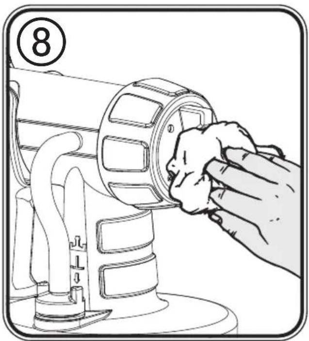
- Wipe off the nozzle and air cap regularly to make sure they do not get blocked. (Fig. 8)
10. Interruption of Work till 4 Hours
- Switch the unit off using the ON/OFF switch (Pos. 0).
• Unplug the power plug. - When processing 2-component varnishes, clean the device immediately.

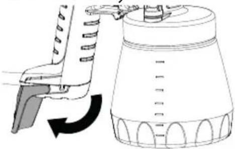
Always fold out the handle extension before placing on the ground if you are using a different spray attachment to the included standard small spray attachment to balance the container height.
natural_image
Diagram of a mechanical device with a lever and rotating arrow, no text or symbols present11. Taking Out of Operation and Cleaning
Proper cleaning is the prerequisite for problem-free operation of the paint application device. No warranty claims are accepted in case of improper or no cleaning.
1) Switch the unit off using the ON/OFF switch (Pos. 0). Vent the container in case of longer breaks and after the work has been terminated. This can be done by briefly turning open and then closing the container or by pulling the trigger guard and letting the paint into the original paint container.
2) Divide the spray gun. Press the hook (Fig. 3 "click") slightly downwards. Turn the gun front part and gun rear part against each other and take them apart.
3) Unscrew the container. Empty any remaining coating material back into the material tin.
4) Pull out the suction tube with container seal.
5) Preclean the container and suction tube with a brush. Clean the ventilating bore (Fig. 9, C).
CAUTION! Never clean seals, diaphragm and nozzle or air holes of the spray gun with metal objects.
The ventilation hose and diaphragm are only solvent-resistant to a limited extent. Do not immerse in solvent, only wipe.
6) Unscrew the union nut (Fig. 9, 1) and remove the air cap (2) and nozzle (3). Clean the air cap, nozzle seal (4) and nozzle with a brush and solvent or water.
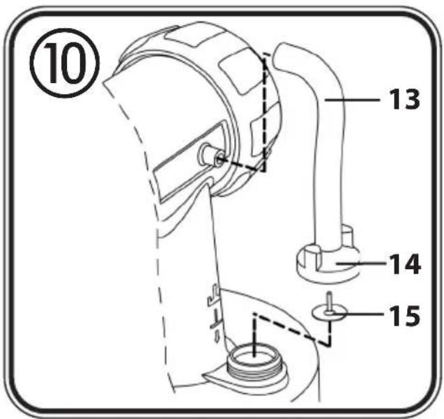
7) The unit may only be operated with an integer diaphragm (Fig. 10, 15). If any paint has penetrated to the ventilation hose, check and clean the membrane (see the Maintenance chapter).

WARNING! Never hold the spray gun rear part under water or immerse it into liquids. Clean the housing only with a moistened cloth.
8) Clean the outside of the spray gun and container with a cloth soaked in solvent or water.
9) Assemble the parts again (see "Assembly").
Assembly

Attention! Never operate the device if the nozzle seal is either damaged or missing. If the nozzle seal is either missing or damaged liquids can enter the device and increase the risk of an electric shock.
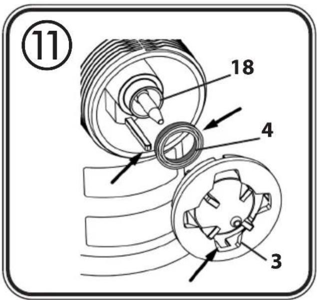
1) Push the nozzle seal (fig. 11, 4) over the needle (18); the groove (slot) should point towards you.
2) Put the nozzle (fig. 11, 3) onto the gun body and find the correct position by turning it.
3) Put the air cap onto the nozzle and tighten it using the union nut.
4) Place the container seal from below on the suction tube and slide it over the collar, while turning the container seal slightly.
5) Insert the suction tube with container seal in the gun body.

In order to mount the gun more easily apply lubricating grease (enclosed) liberally to the O-ring at the gun front part. (Fig. 13, Item 6)
12. Maintenance
Air filter

WARNING! Never operate the machine without the air filter; dirt could be sucked in and interfere with the function of the machine. Disconnect plug before changing parts.
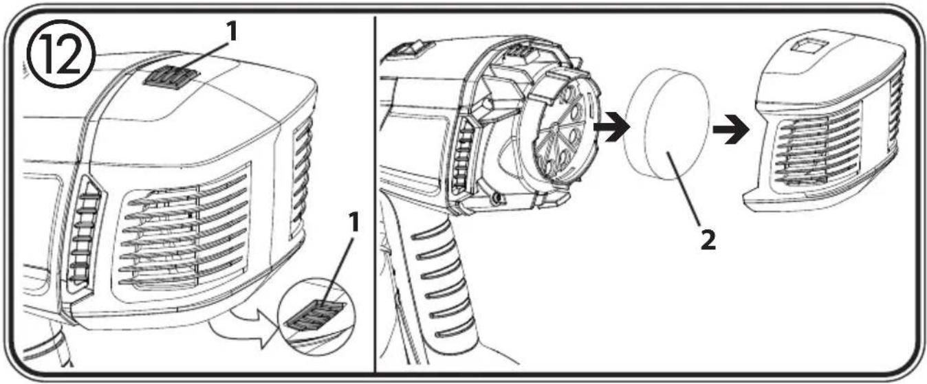
- Press both locks (Fig. 12.1) and remove the filter cover.
- Remove the air filter (2) and replace depending on contamination.
- Click the filter cover in place again.
Ventilating hose/Valve
- Pull the ventilating hose (Fig. 10, 13) at the top from the gun body. Screw off the valve cover (14). Remove the diaphragm (15). Carefully clean all parts or replace in the event of damage.
- Place the diaphragm (Fig. 10, 15) with the pin facing upwards on the bottom section of the valve. Also see the marking on the gun body.
- Place on the valve cover (Fig. 10, 14) and screw it closed.
- Place the ventilating hose (Fig. 10, 13) on the valve cover and on the nipple at the gun body.
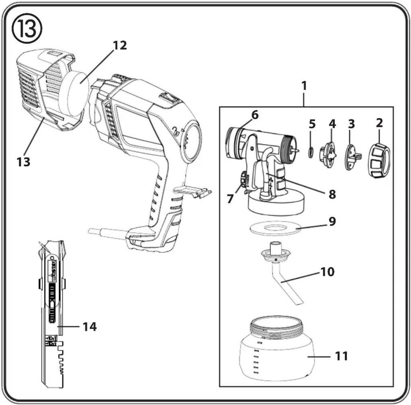
13. Spare Parts List
| Spare Parts List (Fig. 13) | ||
| Pos. | Designation Order No. | |
| 1 | Standard small spray attachment complete incl. 600 ml container | 2370525 |
| 2 | Union nut 2362873 | |
| 3 | Air cap 2362877 | |
| 4 | Nozzle 2362878 | |
| 5 | Nozzle seal 0417706 | |
| 6 | O-ring 2362875 | |
| 7 | Material volume regulation with spring, complete 0417910 | |
| 8 | Ventilating hose, valve cover, diaphragm 2304027 | |
| 9 | Container seal 2370527 | |
| 10 | Suction tube 2371151 | |
| 11 | Container with cover | 2370528 |
| 12 | Air filter | 2370530 |
| 13 | Air filter cover 2370532 | |
| 14 | Stir stick | 2304419 |
| 15 | Lubricating grease (no fig.) | 2315539 |
14. Accessories
The CLICK&PAINT SYSTEM with additional spray attachments and accessories offers the right tool for each work.

We recommend against using the W 150 with the Wall Extra I-Spray spray attachment.
Further information about the WAGNER range of products for renovating is available under www.wagner-group.com
15. Correction of Malfunctions
| Problem | Cause | Remedy |
| No coating material emerges from the nozzle | Nozzle cloggedFeed tube cloggedMaterial volume setting turned too far to the left (-)Feed tube looseNo pressure build-up in container | CleanCleanTurn to the right (+)InsertTighten container |
| Coating material drips from the nozzle | Nozzle looseNozzle wornNozzle seal is missing or wornCoating material assembly at air cap, nozzle or needle | TightenChangeInsert an intact nozzle sealClean |
| Atomisation too coarse | Viscosity of coating material too highMaterial volume too large Material volume adjusting screw turned too far to the right (+)Nozzle contaminatedAir filter heavily soiledToo little pressure build-up in container | ThinTurn material volume adjusting screw to the left (-)CleanChangeTighten container |
| Spray jet pulsates | Coating material in container running outAir filter heavily soiledNozzle seal is missing or worn | RefillChangeInsert an intact nozzle seal |
| Coating material causes "paint tears" | Too much coating material applied. | Turn material volume adjusting screw to the left (-) |
| Too much fog of coating material (Overspray) | Distance to the object too largeToo much coating material applied | Reduce distanceTurn material volume adjusting screw to the left (-) |
| Paint in the ventilating hose | Diaphragm soiledDiaphragm defective | Clean the diaphragmReplace the diaphragm |
- Technical Data
* Measured in accordance with 50580
| Technical Data | |
| Max. viscosity 100 DIN-s | |
| Power source 230 V | ~, 50 Hz |
| Power consumption 300 W | |
| Atomizing output: 70 W | |
| Max. flow rate: 140 ml/min | |
| Protection Class: | I |
| Sound pressure level* | 75 dB (A); Uncertainty K = 4 dB |
| Sound pressure output* | 86 dB (A); Uncertainty K = 4 dB |
| Oscillation level*Weight 1.2 kg | < 2.5 m/s ^2 ; Uncertainty K = 1.5 m/s ^2 |
Information about the oscillation level
The specified oscillation level has been measured according to a standard test procedure and can be used to compare against electric tools.
The oscillation level is also for determining an initial assessment of the vibrational strain.
Attention! The vibration emission value can differ from the specified value when the electric tool is actually in use, depending on how the electric tool is being used. It is necessary to specify safety measures to protect the operating personnel. These measures are based on an estimated shutdown during the actual conditions of use (all parts of the operating cycle are taken into consideration here, for example periods when the electric tool is switched off, and, when it is switched on but running without any load).
17. Environmental protection

The device and all accessories and packaging have to be recycled in an environmentally friendly manner. Do not dispose of the appliance with household waste. Support environmental protection by taking the appliance to a local collection point or obtain information from a specialist retailer. Leftover paint and solvents may not be emptied into drains, the sewage system or disposed of as household rubbish. It has to be disposed of separately as special waste. Please pay special attention to the instructions on the product packaging.
18. Important Note regarding Product Liability!
According to an EU directive, the manufacturer is only liable without limitation for faults in the product if all parts come from the manufacturer or have been approved by the manufacturer and have been mounted to the device and are operated properly. If third-party accessories or spare parts are used, the manufacturer is exonerated wholly or partly from his/her liability if use of the third-party accessories or spare parts have caused a defect in the product.
3 + 1 year guarantee on this WAGNER DIY product
In addition to the statutory warranty for this product, J. Wagner GmbH, based in 88677 Markdorf, Germany, grants you a guarantee (device guarantee) of 36 months for this product. This guarantee is extended by a further 12 months if the product is registered within 28 days of purchase on the Internet at https://go.wagner-group.com/3plus1.
The guarantee includes the free repair of defects which are demonstrably caused by the use of unsuitable materials in the product's manufacture or by assembly errors, as well as the free replacement of faulty components provided there are no guarantee exclusions.
The statutory material defect rights to which you as the purchaser are entitled for the intended purpose from the time of handover of the purchased item are not restricted by the guarantee. The guarantee, along with your statutory warranty rights, will expire if the device has been opened by persons other than authorised WAGNER service personnel. The detailed guarantee conditions can be obtained on request from our authorised WAGNER partners (see website or operating instructions) or in text form on our website:
https://go.wagner-group.com/hf-warranty-conditions

- Modifications reserved -
UKCA Declaration of conformity
We declare under sole responsibility that this product conforms to the following relevant regulations:
Supply of Machinery (Safety) Regulations 2018
Electromagnetic Compatibility Regulations 2016
The Restriction of the Use of Certain Hazardous Substances in Electrical and Electronic Equipment Regulations 2012
The Waste Electrical and Electronic Equipment Regulations 2013
Applied harmonised standards
BS EN 62841-1:2015, BS EN 50580:2012+A1:2013, BS EN IEC 55014-1:2021,
BS EN IEC 55014-2:2021, BS EN 61000-3-2:2019+A1:2021,
BS EN 61000-3-3:2013+A2:2021, BS EN 62233:2008
EU Declaration of conformity
We declare under sole responsibility that this product conforms to the following relevant stipulations:
2006/42/EC, 2014/30/EU, 2011/65/EU, 2012/19/EU
Applied harmonised norms:
EN 62841-1, EN 50580, EN 55014-1, EN 55014-2, EN IEC 61000-3-2, EN 61000-3-3, EN 62233
The EU declaration of conformity is enclosed with the product.
If required, it can be re-ordered using order number 2371193.
Warning
If the supply cord of this appliance is damaged, it must only be replaced by a repair shop appointed by the manufacturer, because special purpose tools are required. The wires in this mains lead are coloured in accordance with the following code:
$$ \begin{array}{c} \text {green / yellow = earth} \ \text {blue = neutral brown = live} \end{array} $$
As the colours of the wires in the mains lead of this appliance may not correspond with the coloured markings identifying the terminals in your plug, proceed as follows:
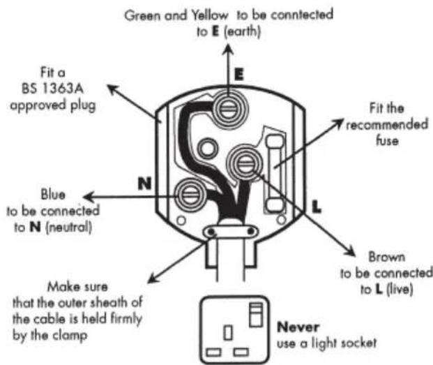
- The wire which is coloured green and yellow must be connected to the terminal in the plug which is marked with the letter E or by the earth symbol or coloured green or green and yellow.
- The wire which is coloured blue must be connected to the terminal which is marked with the letter N or coloured black.
- The wire which is coloured brown must be connected to the terminal which is marked with the letter L or coloured brown.
- Should the moulded plug have to be replaced, never re-use the defective plug or attempt to plug it into a different 13 A socket. This could result in an electric shock.
- Should it be necessary to exchange the fuse in the plug only use fuses approved by ASTA in accordance with BS 1362. Only 13 Amp fuses may be used.
- To ensure that the fuse and fuse carrier are correctly mounted please observe the provided markings or colour coding in the plug.
• After changing the fuse, always make sure that the fuse carrier is correctly inserted. Without the fuse carrier, it is not permissible to use the plug. - The correct fuses and fuse carriers are available from your local electrical supplies stockist.
natural_image
Diagram of a laboratory instrument with a curved arrow indicating rotation or movement (no text or symbols present)natural_image
Diagram of a cleaning or cleaning device with a tool and brush, showing a curved arrow indicating rotation (no text or symbols present)https://go.wagner-group.com/hf-warranty-conditions

natural_image
Diagram of a mechanical device with a lever and curved arrow indicating rotation (no text or symbols)natural_image
Diagram of a laboratory instrument with a curved arrow indicating rotation or movement (no text or symbols present)https://go.wagner-group.com/hf-warranty-conditions

GB Inspiration of a very special kind
Are you on the look-out for your next project? Then take a look at our project finder. Here, you'll find practical guides on renovation, decoration and DIY. Make your home unique. Make it beautiful!

natural_image
Black-and-white photo of a woman sitting in a wicker chair on a wooden deck, with potted plants and a glass table nearby (no visible text or symbols)natural_image
Interior scene of a woman sitting in a chair near a window with a potted plant, bookshelf, and painting on the wall (no visible text or symbols)natural_image
Black-and-white photo of a person pushing a wheelbarrow beside a wooden fence in a garden setting (no visible text or symbols)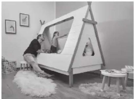
natural_image
Interior scene of a child playing with a wooden play structure, surrounded by rug and wall art (no visible text or symbols)D Mehr Inspiration?
wagner-group.com/projects
GB More inspiration?
wagner-group.com/projects

natural_image
Black-and-white photo of a woman operating a manual lawn machine outdoors, surrounded by gardenery and a wooden deck (no visible text or symbols)D
J. WAGNER GMBH
Silverstone Park, Silverstone
Northants NN12 8GX
T + 44 (0) 1327 368410
DK
DVA A/S
Marielundvej 48 C
2730 Herlev
T+45 70 234 239
DK
ORKLA HOUSE CARE DANMARK A/S
Stationsvej 13
3550 Slangerup
Danmark
T+45 47 33 74 00
F+45 47 33 74 01
NOR
ORKLA HOUSE CARE NORGE AS
41-605 Swietochlowice
T+48/32/346 37 00
F +48/32/346 37 13
SCH
ORKLA HOUSE CARE AB
Box 133
564 23 Bankeryd
Sweden
T +46(0)36 37 63 00
ROM
ROMIB S.R.L.


- WOOD & METAL SPRAYER
- W 150
- HERZLICHEN DANK FÜR IHR VERTRAUEN
- Translation of the original operating instructions
- MANY THANKS FOR PLACING YOUR TRUST IN US
- Contents
- Explanation of symbols used
- General Safety Instructions
- Caution!
- Safety at the workplace
- Electrical Safety
- Safety of Persons
- Usage and treatment of the electric tool
- Service
- Safety Instructions for Spray Guns
- Description/ Scope of delivery
- Coating Materials
- Start-up
- Adjusting the desired Spray Setting
- Adjusting the Material Volume (Fig. 6)
- Spray Technique
- Interruption of Work till 4 Hours
- Taking Out of Operation and Cleaning
- Proper cleaning is the prerequisite for problem-free operation of the paint application device. No warranty claims are accepted in case of improper or no cleaning.
- Assembly
- Attention! Never operate the device if the nozzle seal is either damaged or missing. If the nozzle seal is either missing or damaged liquids can enter the device and increase the risk of an electric shock.
- Maintenance
- Air filter
- WARNING! Never operate the machine without the air filter; dirt could be sucked in and interfere with the function of the machine. Disconnect plug before changing parts.
- Ventilating hose/Valve
- Spare Parts List
- Accessories
- Correction of Malfunctions
- Information about the oscillation level
- Environmental protection
- Important Note regarding Product Liability!
- + 1 year guarantee on this WAGNER DIY product
- UKCA Declaration of conformity
- EU Declaration of conformity
- Warning
- GB Inspiration of a very special kind
- WAGNER GMBH
- DVA A/S
- ORKLA HOUSE CARE DANMARK A/S
- ORKLA HOUSE CARE NORGE AS
- ORKLA HOUSE CARE AB
- ROMIB S.R.L.
Brand : WAGNER
Model : W 150
Category : Paint spray