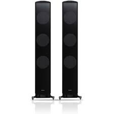
S-71 (X1) - Pregnant PIONEER - Free user manual and instructions
Find the device manual for free S-71 (X1) PIONEER in PDF.



User questions about S-71 (X1) PIONEER
0 question about this device. Answer the ones you know or ask your own.
Ask a new question about this device
Download the instructions for your Pregnant in PDF format for free! Find your manual S-71 (X1) - PIONEER and take your electronic device back in hand. On this page are published all the documents necessary for the use of your device. S-71 (X1) by PIONEER.
USER MANUAL S-71 (X1) PIONEER
STRØMFORSYNT SUBWOOFER
TEHOLLINEN APUBASSO
AKTINBHyI CAEByΦEP
Discover the benefits of registering your product online at http://www.pioneer.co.uk (or http://www.pioneer.eu).
Thank you for buying this PIONEER product. Please read through these operating instructions so you will know how to operate your model properly. After you have finished reading the instructions, put them away in a safe place for future reference. In some countries or regions, the shape of the power plug and power outlet may sometimes differ from that shown in the explanatory drawings. However, the method of connecting and operating the unit is the same.
IMPORTANT

The lightning flash with arrowhead symbol, within an equilateral triangle, is intended to alert the user to the presence of uninsulated "dangerous voltage" within the product's enclosure that may be of sufficient magnitude to constitute a risk of electric shock to persons.
CAUTION
RISK OF ELECTRIC SHOCK DO NOT OPEN
CAUTION:
TO PREVENT THE RISK OF ELECTRIC SHOCK,DO NOT REMOVE COVER (OR BACK).NO USER-SERVICEABLE PARTS INSIDE.REFER SERVICING TO QUALIFIED SERVICE PERSONNEL.

The exclamation point within an equilateral triangle is intended to alert the user to the presence of important operating and maintenance (servicing) instructions in the literature accompanying the appliance.
D3-4-2-1-1_A1_En
WARNING
This equipment is not waterproof. To prevent a fire or shock hazard, do not place any container filled with liquid near this equipment (such as a vase or flower pot) or expose it to dripping, splashing, rain or moisture.
D3-4-2-1-3_A1_En
WARNING
Before plugging in for the first time, read the following section carefully.
The voltage of the available power supply differs according to country or region. Be sure that the power supply voltage of the area where this unit will be used meets the required voltage (e.g., 230V or 120V ) written on the rear panel.
D3-4-2-1-4*A1En
WARNING
To prevent a fire hazard, do not place any naked flame sources (such as a lighted candle) on the equipment.
D3-4-2-1-7a_A1_En
VENTILATION CAUTION
When installing this unit, make sure to leave space around the unit for ventilation to improve heat radiation (at least 15cm at top, 15cm at rear, and 15cm at each side).
WARNING
Slots and openings in the cabinet are provided for ventilation to ensure reliable operation of the product, and to protect it from overheating. To prevent fire hazard, the openings should never be blocked or covered with items (such as newspapers, tablecloths, curtains) or by operating the equipment on thick carpet or a bed.
D3-4-2-1-7b*A1En
Operating Environment
Operating environment temperature and humidity: +5^ to +35^ (+41^ to +95^) less than 85% RH (cooling vents not blocked)
Do not install this unit in a poorly ventilated area, or in locations exposed to high humidity or direct sunlight (or strong artificial light)
D3-4-2-1-7c*A1_EN
If the AC plug of this unit does not match the AC outlet you want to use, the plug must be removed and appropriate one fitted. Replacement and mounting of an AC plug on the power supply cord of this unit should be performed only by qualified service personnel. If connected to an AC outlet, the cut-off plug can cause severe electrical shock. Make sure it is properly disposed of after removal. The equipment should be disconnected by removing the mains plug from the wall socket when left unused for a long period of time (for example, when on vacation).
D3-4-2-2-1a A1_En
CAUTION
The POWER switch on this unit will not completely shut off all power from the AC outlet. Since the power cord serves as the main disconnect device for the unit, you will need to unplug it from the AC outlet to shut down all power. Therefore, make sure the unit has been installed so that the power cord can be easily unplugged from the AC outlet in case of an accident. To avoid fire hazard, the power cord should also be unplugged from the AC outlet when left unused for a long period of time (for example, when on vacation).
D3-4-2-2-2a*A1En
POWER-CORD CAUTION
Handle the power cord by the plug. Do not pull out the plug by tugging the cord and never touch the power cord when your hands are wet as this could cause a short circuit or electric shock. Do not place the unit, a piece of furniture, etc., on the power cord, or pinch the cord. Never make a knot in the cord or tie it with other cords. The power cords should be routed such that they are not likely to be stepped on. A damaged power cord can cause a fire or give you an electrical shock. Check the power cord once in a while. When you find it damaged, ask your nearest PIONEER authorized service center or your dealer for a replacement.
S002*A1En
WARNING:
Do not climb or sit on this unit. Be especially careful when children are around. The unit may be damaged, or may fall over causing injury.
If you want to dispose this product, do not mix it with general household waste. There is a separate collection system for used electronic products in accordance with legislation that requires proper treatment, recovery and recycling.
Private households in the member states of the EU, in Switzerland and Norway may return their used electronic products free of charge to designated collection facilities or to a retailer (if you purchase a similar new one).
For countries not mentioned above, please contact your local authorities for the correct method of disposal.
By doing so you will ensure that your disposed product undergoes the necessary treatment, recovery and recycling and thus prevent potential negative effects on the environment and human health.
K058b_A1_En
CONTENTS
ACCESSORY ITEMS 4
FEATURES 4
IN COMBINATION WITH
SPEAKERS 4
INSTALLATION 4
Speaker Installation 4
Installation Precautions 5
PANEL FACILITIES. 6
FRONT PANEL. 6
REAR PANEL 6
CONNECTIONS 7
LINE LEVEL CONNECTION 7
OPERATION 7
SPECIFICATIONS. 7
TROUBLESHOOTING 8
ACCESSORY ITEMS
- RCA plug cord x 1
Power cord x 1
Warranty card - Operating instructions (this document)
FEATURES
Extended Low Frequency Response
High linearity magnetic circuit
Phase Control Technology
IN COMBINATION WITH SPEAKERS
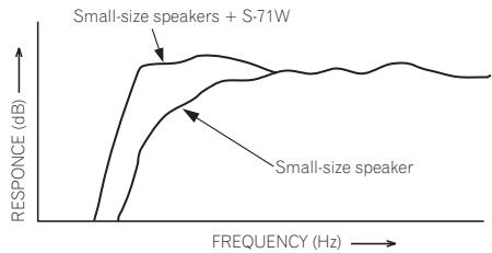
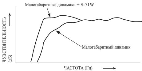
The frequency characteristics of the S-71W combined with small-size speakers are shown below. As shown in these figures, the low frequency range is improved.
- These special characteristics are obtained in an echoless chamber. The effect of an additional S-71W in an ordinary listening room is better than the chart indicates when positioned adequately.
-
With playback of Dolby* Digital, establishment of a special channel for the subwoofer is recommended; and with playback of LFE (Low Frequency Effect: sound effect like the rumbling of the earth, whose purpose is to intensify the force of the video), the S-71W is especially effective.
-
Manufactured under license from Dolby Laboratories. "Dolby" and the double-D symbol are trademarks of Dolby Laboratories.
INSTALLATION
Speaker Installation
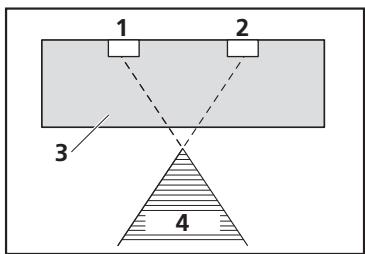
- Subwoofer Installation Criteria
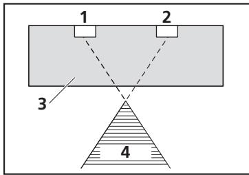
1 Left speaker
2 Right speaker
3 Recommended installation range for the subwoofer
4 Listening position
The subwoofer plays back the bass in monaural, making use of the fact that the human ear is not very sensitive to the direction of low-pitched sound. Because of this, the subwoofer can be installed almost anywhere. If it is installed too far away, however, the sound from the other speakers may become unnatural.
- An example of speaker positioning
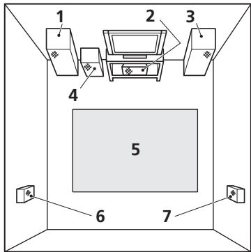
1 Front left speaker
2 Center speaker
3 Front right speaker
4 Subwoofer
5 Listening area
6 Rear left speaker
7 Rear right speaker
NOTES:
- Position the left and right channel speakers at equal distances from the TV set and approximately 1.8 meters from each other.
- Install the center speaker above or below the TV so that the sound of the center channel is localized at the TV screen.
- The rear (surround) speakers are most effective when installed in parallel locations directly to the side, or slightly behind, the listener, at a level about 1 meter above the listener's ears.
CAUTION:
When installing the center speaker on top of the TV, be sure to secure it with tape or some other suitable means. Otherwise, the speaker may fall from the TV due to external shocks such as earthquakes, and it may lead to endangering those nearby or damaging the speaker.
Installation Precautions
- Do not attach the subwoofer to the wall or ceiling. They may fall off and cause injury.
- Install the unit in a well-ventilated location where it will not be exposed to high temperatures and high humidity.
- Do not place the unit near stoves or other heating equipment or at locations exposed to direct sunlight, as these can have an adverse effect on the cabinet and internal components. Also, do not install the unit where there is too much dust or high humidity, as these can cause malfunctioning or breakdowns. (Avoid cooking tables and other locations where the unit would be exposed to heat, steam and soot.)
-
Do not place heavy or large objects on top of the speaker. Doing so could provoke the speaker to fall, causing damages or bodily injury. If speakers fall from their installation locations, they may suffer irreparable cracks in their finish.
-
Keep the unit away from devices such as cassette decks which are sensitive to magnetic fields.
The subwoofer is not magnetically shielded and so should not be placed near a CRT-based TV or color monitor. Magnetic storage media (such as floppy discs and tape or video cassettes) should also not be kept close to the subwoofer.
- Do not place the speaker on an unstable surface, as doing so may cause the speaker to fall and cause damage or bodily injury.
- Do not place cups, glasses, or other containers with fluids on top of the units, since the units may be damaged if the liquid spills.
- The installation location selected should have a sturdy floor surface. Mounting the speaker on a long-pile carpet should be avoided, since the carpet may touch the driver's diaphragm, causing distorted sound.
- Please install this unit away from the antenna cable of the tuner, as noise can be caused with installation close to the antenna cable. In such a case, use this unit at a position away from the antenna and the antenna cable, or when playback of extra bass is not required, switch off the power for this unit.
MAINTENANCE OF EXTERNAL SURFACES:
- Clean the surface by wiping with a soft, dry cloth.
- When the surfaces are very dirty, wipe with a soft cloth dipped in some neutral cleanser diluted five or six times with water, and wrung out well, and then wipe again with a dry cloth. Do not use furniture wax or cleaners.
- Never use thinners, benzine, insecticide sprays and other chemicals on or near this unit, since these will corrode the surfaces.
PANEL FACILITIES FRONT PANEL
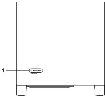
REAR PANEL

1 Power Indicator (STANDBY/ON)
Lights blue when the power has been switched ON. Lights red when the unit is in the standby condition.
NOTE:
- The power is still supplied even when the power indicator is off. The power plug (interrupter) must be unplugged in order to completely cut the power supply. When not using this product for long periods of time, such as when traveling, unplug the power cord (interrupter) from the power outlet for safety purposes. Failure to do so could lead to fire.
2 Power switch (POWER)
Switches the subwoofer between ON and OFF.
3 Volume knob (VOLUME)
Sets the subwoofer volume.
- Turn the knob slowly from the MIN position.
- With this unit, the bass level can be independently set, so do not turn up the bass on the AV amplifier.
4 Auto Standby switch (AUTO STANDBY)
Turning the Auto Standby function on or off.
NOTE:
- The default setting for Auto Standby switch is ON.
Auto standby function
The power is automatically set to the standby mode (off) if there is no input signal for approximately 12 minutes (the power indicator turns red). The power automatically turns on when a signal is input. The auto standby function is deactivated when Auto Standby switch is set to OFF.
NOTE:
- There may be cases where a connected component outputs noise or some other non-audio signal which causes this system to automatically power on when in Auto Standby mode. If this happens, switch off the Auto Standby mode and switch the system on/off manually.
5 Phase switch (PHASE)
When set to 180^ , the output phase becomes the reverse of the input signal, and when set to 0^ , it is in the same phase as the input signal.
- Normally, the switch is set to 0^ . But when the sound connection between the subwoofer and the left and right speakers sounds unnatural, try switching to 180^ and set the switch in the position where the sound is natural.
6 Line Level Output terminal (LINE OUT)
Used for connecting other equipment through the amplifier. The signal output from this jack is not affected in any way by the settings of the various controls on the unit.
7 Line Level Input terminal (LINE IN)
Connect to the SUBWOOFER PREOUT terminal of an amplifier or receiver, with the specially provided RCA plug cord.
8 AC IN
- Connect the power cord to the powered subwoofer unit's AC IN.
- Connect the power cord to an AC socket.
CONNECTIONS
Before making or changing any connections, switch off the power and disconnect both this unit and the amplifier/receiver from the AC outlet.
LINE LEVEL CONNECTION
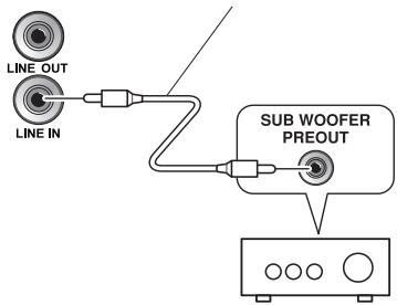
Rear Panel Supplied RCA plug cord
Connect the set's LINE IN terminal to the amplifier or receiver's SUBWOOFER PREOUT terminal using the included RCA pin cord.
NOTE:
- When connected to the PREOUT terminal for surround center channel on the amplifier or receiver, the bass is heard only on the center channel, so it will be insufficient.
Connect the power cord for this unit to the unit's power connector (AC IN), and the other ends to an AC power supply. When turning on the power, turn on the power to the amplifier first, then the power to this unit.
OPERATION
For details regarding operating part functions, refer to PANEL FACILITIES on page 6.
-
Turn the POWER switch (2) ON.
-
If the unit's power cord is connected to a switched AC outlet on the amplifier or receiver and the switch is left ON, the unit can be turned ON/OFF together with the amplifier or receiver.
- If the unit cannot be connected to the amplifier or receiver, turn the power to the amplifier or receiver ON before turning the power to the unit ON. When turning the power OFF, turn the power to the unit OFF before turning the power to the amplifier or receiver OFF.
2. Operate the amplifier or receiver and adjust the volume of the other speakers.
3. Adjust the volume of the bass with the VOLUME knob (3).
- When necessary, operate the PHASE switch (5) and then adjust with the VOLUME knob (3).
4. Turn the POWER switch (2) OFF.
- The power indicator disappears.
CAUTION:
- Do not use the speaker to output distorted sound for long periods of time. This can result in damages to the speaker and poses a potential fire hazard.
SPECIFICATIONS
Cabinet........... Bass-reflex, floor type
Speaker............ 25 cm cone type
Power Amplifier Continuous Power Output (RMS) 160 W/6 Ω (100 Hz) Input (sensitivity at 100 Hz)
LINE LEVEL (RCA jack) 190 mV
Outline Dimension
372 mm (W) x 394 mm (H) x 412 mm (D)
Weight (without package) 19.3 kg Power Requirements
220Vto 240V ,50Hz/60Hz
Power Consumption 130 W
Power consumption in standby. .0.45 W less
Specifications and design subject to possible modification without notice, due to improvements.
Published by Pioneer Corporation.
Copyright © 2009 Pioneer Corporation.
All rights reserved.
TROUBLESHOOTING
Incorrect operations are often mistaken for trouble and malfunctions. If you think that there is something wrong with this component, check the points below. Sometimes the trouble may lie in another component. Investigate the other components and electrical appliances being used. If the trouble cannot be rectified even after exercising the checks listed below, ask your nearest PIONEER authorized service center or your dealer to carry out repair work.
| SYMPTOM | CAUSE | REMEDY | |
| 1 | No power is being supplied (Indicator does not light up when power switch is turned on.) | • Power supply plug is not correctly inserted. | • Insert plug securely. |
| 2 | No sound (Indicator is lit blue.) | • Connection of accessory RCA plug cord is wrong or disconnected. • VOLUME knob is set to MIN. | • Check again and connect correctly. • Turn clockwise slowly. |
| 3 | Sound is distorted. | • Level is too high. • Input level is too high. | • Turn the VOLUME knob counterclockwise to lower the level. • Turn the amplifier's output level (volume, bass control, bass boost) counter-clockwise to lower the level. |
| 4 | Howling noise occurs. | • No power supplied to the amplifier. • Subwoofer level is set too high. | • Connect an amplifier and supply power. • Place the subwoofer a good distance from speakers. Turn the VOLUME knob counterclockwise to lower the volume. |
| 5 | Much noise when listening to AM or FM broadcasts. | • The AM loop antenna or the FM indoor antenna is close to this unit. | • Increase the distance between the AM or FM antenna (for indoor use) and this unit. |
| 6 | Sound is broken. | • Auto standby function is on. | • Turn the auto standby function off. |
| 7 | No sound (Indicator is lit red.) | • No input signal. | • Turn the auto standby function off. |
ACCESSIONS FOURNIS 4
CHARACTERISTIQUES. 4
UTILISATION COMBINÉE AVEC
DES ENCEINTES ACOUSTIQUES. 4
INSTALLATION 4
Publication de Pioneer Corporation.
© 2009 Pioneer Corporation.
WAARSCHUWING NETSNOER
Copyright © 2009 Pioneer Corporation.
I KOMBINATION MED HÖGTALARE......4
INSTALLERING. 4
Installering av hoga talaren. 4
Observera vidinstalling. 5
REGLAGENS PLACERING. 6
FRAMSIDAN 6
BAKSIDAN. 6
ANSLUTNINGAR 7
LINJENIVÄANSLUTNING. 7
ANSLUTNING AV NÄTKABELN.8
TILLVÄGAGANGSSÄTT 8
TEKNISKA DATA 8
FELSÖKNING. 9
I KOMBINATION MED HÖGTALARE
Published by Pioneer Corporation. Copyright © 2009 Pioneer Corporation. All rights reserved.
FEJLFINDING
I KOMBINASJON MED HÖYTTALERE
2 Strømbryter (POWER)
YcTaHOBka IHHaMHKOB 4
MepbI IpeIOCTOPOKHOCTH IIpy ycTaHOBKe ....5
OPRAHbI IOKJIIOUeyHnI
YNPABJIENHA BHEUHNX
IIAHENIX 6
IIPEIINHJIY IAIHEJIb. 6
3AДнЯ ПАHEЛь. 6
COEINHEHNA 7
COEINHEHNE JIJIHNHO
CNTHAJIA 7
IODCOEINHEHNE UHUPA
PINTAHNA 8
PABOTA C YCTPOIcTBOM 8
TEXHUNECKNE XAPAKTEPNCTNUKII.....8
ПОИСК И YYSTРАЕНЕ HЕПОЛДАК...9
ПРИЛАГАБМБЕ ПРИНДЛЕЖHOCTN
Ka6eJIb cpa3BeMOM RCA x 1
- IIHypпнтаянх1
- FapaHTHnHbI TaJIOH
- INHCTpyKIIH NO 3KcIIyataHH (JaHHbI JOKUMENT)
ФУHKUHOHAJIbHbIE BO3MOXHOCTN
PacHINpeHHbIe HN3KoYacTOTHbIe xapakTepcTHKN
MaHHTaIeIb C BbICOKOJIINHeHOCtBIO
TexHIOIgHnpeRyJInpOBKnΦa3bI
B COYETAHN C DInHAMNKAMN
YactOTHbIe XapaKTePncTHKnS-71W BcoetyAHn cMaJIOra6apHTbIMN HnHaMHKaMn IIpNBedeHb HnKe. KaBnDHO n3 IIpNBeEeHHbIX nHΦp, yJIyUHeH dHaNa3OH Hn3KHX YactOT.
- ΘTN cπeπηλIbHbIe xapaKterpHcTHKn ΜIoJIyUeHbI B KAMpe 6e3 3XooTpaJxKeHn. ΘΦΦeKT ΦΠΟJIHHTeJIbHOrO S-71W B ΜθυHOM ΜΠeMεHnДΙ ΠροCιIyIuHbAHHaHδyIET ΦIyUHII ΦIpo CpaBHeHnO C ΠρινBéHbIMn Ha rpaΦke XapaKterpHcTHKnKaMn, eζIη yctPoiCTBO paCIOLOJxKeHo IpaBnIbHo.
-ПинВOCIPINOH3BeHENHcHcIOJIb3OBaHNem Dolby* Digital peKOMeHdyetca yCTAHABJIBBaTb CIIeIHaJIbHbI KaHJIДЯ ca6Byfepa;аПинВOCIPINOH3BeHENHc HcIOJIb3OBAHNEM LFE (Low Frequency Effect -Hn3KoYAcTOTHbIe 3ykoBoi 3ΦΦeKtB:3ByKOBoI 3ΦΦeKt, HAIOMINHOII INpOkaHne 3EmIn, IpeIHa3HaueHdIy ycHJIeHnI 3ΦΦeKtA BnDeO) S-71W Ooc6EHNO 3ΦΦeKTHBEH.
- H3zomob6IeNo no luuehen3uu KOMnauuu Dolby Laboratories. «ДоI6u» u 3нak e 6ube de6oHoui 6yK6bDЯ6IhOmca moBapnmu 3naKamu KOMnauu Dolby Laboratories.
YCTAHOBKA
YcTaHObKa DnHaMnKOB
Kpntepnn yctaHOBkn ca6ByΦepa
1 JIeBbI dHaMVK
2 PpaBbI dHnHaMnK
3 PeKOMeHnyembIi Dnana3OH yCTaHOBKn ca6ByΦepa
4 P03nucnCnywataTena
Ca6ByepeB OBCnpoH3BOJNT HN3KoUacTOTHbIe 3ByKn B MOHOfoHNHeCKOM peXHMe, IIOJIb3yAcB TeM, YTO HeOChEh YUBCTBHTeJIbHO IO OTHOIIeHNIO K HAnpAbJIeHNIO HN3KNX 3ByKOB.БlaOrdApA TcMOY Ca6Byepe MoKeT 6bITb yCTaHOBJEIN IIpaKTHeeCKN B JIObOM MeCe. OJNaKO, ECJN OH yCTaHOBJEIN CJINIKOM DAJIeKO, 3BYK, BOcIPOn3BODIMbIpyrHMN DHHAMNKAMH, MoKeT 3BYuATb HeecTeCTBeHHO.
PABOTA C YCTPOICTBOM
3a IIOIPO6HOH INHΦOPMaIIeH O ΦyHKIIHX opraHOB yIPaBJIeHN O6paIIaIteCb K pa3JeIy OPRAHBI IIOJIKIIIOYEHIN I YIIPABJIeHN HA BHEIIHHX IIAHEJIAX Ha cTp. 6.
- NapeKJIIOUHTe BbIKIOUaTeIb NITAHNPOWER (2) B NOJIOXHeHb BKJIIOUeHnR (ON).
EclnIINHyp IITaHnY yCtpoHCTBa IIOIKJIOueH K BCIOOMoTaTeJIbHOI IpeKJIIOaEMo pO3eTKe cETN IepemEHNO TOKa Ha ycJIInTeJIe HJIIn pecHBpe, a BbIKJIOaTeJIb IITaHHo OCTabJIeH yCTaHOBJIeHHbIM B IOJOxKeHHe BKIIIOUeHHa (ON), ycTpoICTBO MOJHO BKIIIOuATb H bIKJIOuaTb OJHOBpeMeHHo C ycJIInTeJIe HJIIn pecHBepom.
Korda daHHoe yctpoCTBO He moKet 6bITb IIOcoeINHeHO K PO3ETke Ha ycHJIInTeJe HIN peCHepe, BKJIOuaIte IINTaHHe ycHJIInTeJe HIN peCHepeA DO TORO, KaK BKJIIOuAteB IIHTaHHe DaHHoro yctpoCTBa. PnB BbIKJIIOUeHN IIITaHHe BbIKJIIOuaIte IIHTaHHe ycTPOIcTBA IpeE d Tem, KaK BbIKJIIOUHTb IIITaHHe ycHJIInTeJe HIN peCHepeA.
2. BbInOpHnTe Heo6xOdMlbIe onepaun c ycHInTeJIem nI IN peCINBepOM n HacTpoIte yPoBeHb rPOMKocTN dpyrNX DInHaAMNKOB.
3. HacptpoTe ypoBeHb rPOMKocTn HN3KOyAcTOThbIX 3ByKOB C NOMOuBIO pyuKn VOLUME (3).
Ipn Heo6xOJIMOCTH OTpepyHpyTe IIOJOKeHHe IpeKJIOnaTeJIa 5bI PHASE (5), a 3aTeM HacToPeYyPoBeHb rPOMKoCTN c IOMOIIbIO pyKN VOLUME (3).
- NapeKJIIOUHTe BbIKIOUaTeIb PNTAHNPOWER (2) B noJIOXeHne BbIKIOUcEHN (OFF).
- INHdkatop nHTaHHnIgacHeT.
BHIMAHNE:
He IOnIyckaJIte BbIBOJ chepe3 rPOMKOrOBOpHTeJIb NCKAKeHHoro 3Byka B TeueHHe IJIInTeJIbHoro IepHOJa BpeMeHN.3To MoKet BbI3BaTb IOBpeKJDeHne rPOMKOrOBOpHTeJIa H CO3JaTe IOTeHIIaJIbHyIOIaChOcTB BO3rOpaHHa.
TEXHNUECKNE XAPAKTEPNUCTNIKNI
Kopnyc
HaIOJIbHOrO TINa c OtpaKaTeJIeM 6acOB
HnHAMNK. 25cm KOHycHOrO THIIa
HeIpepbBna BbIXoIHnA MOuHocTb yCHInTeJIa
MOUHOCTHR (RMS) 160BT/6Ω(100Tt)
BXoJ (YyBCTBHTeJIbHocTb IIpy 100Tt)
JIINHEINHbI BXoJ (pa3bEm RCA) .190MB
TgabapHTbIe pa3mepbl
372 MM (III) x 394 MM (B) x 412 MM (Д)
Bec (6e3 yIaKOBKN). 19,3 Kf
Tpe6oBaHnK OJIeKTPoIHNTaHHo
OT 220 Bdo 240 B~, 50 Tt/60 Tt
IOTpe6JIeMaMA MOUHocTb. 130BT
IOTpe6JIeMaMA MOUHocTb B peKHMe OKnJaHHa
.0,45BT HIN Mehblie
TexHHueckHe xapaKTepeHCTKN H KOHcTpkyIHH MoTy MeHrTbc8 63 IpeJIbAhpTEJIbHO rByEOMJIeHHB C BcB3N C BHOCHMbIMn ycOBePIIeHCTBOBaHHaMH.
Издано Pioneer Corporation.
Pioneer Corporation, 2009.
Published by Pioneer Corporation.
Copyright © 2009 Pioneer Corporation.
All rights reserved.
Publication de Pioneer Corporation.
© 2009 Pioneer Corporation.
PIONEER ELECTRONICS (USA) INC.
P.O. BOX 1540, Long Beach, California 90801-1540, U.S.A. TEL: (800) 421-1404
PIONEER ELECTRONICS OF CANADA, INC.
300 Allstate Parkway, Markham, Ontario L3R 0P2, Canada TEL: 1-877-283-5901, 905-479-4411
PIONEER EUROPE NV
Haven 1087, Keetberglaan 1, B-9120 Melsele, Belgium TEL: 03/570.05.11
PIONEER ELECTRONICS ASIACENTRE PTE. LTD.
253 Alexandra Road, #04-01, Singapore 159936 TEL: 65-6472-7555
PIONEER ELECTRONICS AUSTRALIA PTY. LTD.
178-184 Boundary Road, Braeside, Victoria 3195, Australia, TEL: (03) 9586-6300
PIONEER ELECTRONICS DE MEXICO S.A. DE C.V.
Blvd.Manuel Avila Camacho 138 10 piso Col.Lomas de Chapultepec, Mexico,D.F. 11000 TEL: 55-9178-4270
K002_Ru