
WHSDC0709J3E5 - Air-conditioner PANASONIC - Free user manual and instructions
Find the device manual for free WHSDC0709J3E5 PANASONIC in PDF.
| Product type | Air-to-water heat pump (split system) |
| Brand | Panasonic |
| Model | WHSDC0709J3E5 |
| Refrigerant | R32 (mildly flammable) |
| Power supply | 230 V AC |
| Operating modes | Heat, Cool (unlockable by installer), Auto, DHW tank |
| Water outlet temperature range (Heat) | 20 to 55 °C (depending on outdoor temperature) |
| Water outlet temperature range (Cool) | 5 to 20 °C |
| Outdoor temperature range (Heat) | -20 to 35 °C |
| Outdoor temperature range (Cool) | 10 to 43 °C |
| Remote controller | LCD screen, directional keys, adjustable backlight |
| Weekly programming | Up to 6 slots per day |
| Silent mode | 3 adjustable levels |
| Sterilization function (anti-legionella) | Configurable (day, time, temperature, duration) |
| DHW capacity | Variable or standard (depending on setting) |
| Electric backup | Activable for heating and/or DHW tank |
| Bivalent connection | Possible with boiler in alternating, parallel, or advanced parallel |
| Optional connectivity | Network adapter (Panasonic Smart app) |
| Frost protection | Activable when stopped |
| Error display | HXX and FXX codes on remote controller |
| Maintenance | Annual cleaning of water filter, clearing of outdoor air intakes |
| Safety | RCCB/ELCB circuit breaker, refrigerant leak detection |
| Standards | R32 – compliance with minimum room area (Amin) |
Frequently Asked Questions - WHSDC0709J3E5 PANASONIC
User questions about WHSDC0709J3E5 PANASONIC
0 question about this device. Answer the ones you know or ask your own.
Ask a new question about this device
Download the instructions for your Air-conditioner in PDF format for free! Find your manual WHSDC0709J3E5 - PANASONIC and take your electronic device back in hand. On this page are published all the documents necessary for the use of your device. WHSDC0709J3E5 by PANASONIC.
USER MANUAL WHSDC0709J3E5 PANASONIC
Operating Instructions
Air-to-Water Heatpump
natural_image
Exterior view of a modern industrial water heater unit (no visible text or symbols)Model No.
Indoor Unit Outdoor Unit
WH-SDC0305J3E5 WH-UD03JE5*
WH-UD05JE5*
WH-SDC0709J3E5 WH-UD07JE5*
WH-UD09JE5*


Manufactured by:
Panasonic AVC Networks Czech, s.r.o.
U Panasoniciku 1, 320 84 Plzeň, Czech Republic
Operating Instructions
Air-to-Water Heatpump
2-39
English (EN)
Thank you for purchasing Panasonic product.
Before operating the system, please read these operating instructions thoroughly and keep them for future reference.
Installation Instructions attached.
Serial number and production year please refer to name plate.
Table of contents
Safety precautions 4-16
Remote Controller buttons and display 17-19
Initialization 19
Quick Menu 20
Menus 20-34
For user
1 Function setup 20-21
1.1 Weekly timer
1.2 Holiday timer
1.3 Quiet timer
1.4 Room heater
1.5 Tank heater
1.6 Sterilization
2 System check 22
2.1 Energy monitor
2.2 System information
2.3 Error history
2.4 Compressor
2.5 Heater
3 Personal setup 22-23
3.1 Touch sound
3.2 LCD contrast
3.3 Backlight
3.4 Backlight intensity
3.5 Clock format
3.6 Date & Time
3.7 Language
3.8 Unlock password
4 Service contact 23
4.1 Contact 1 / Contact 2
For installer
5 Installer setup > System setup .....24-29
5.1 Optional PCB connectivity
5.2 Zone & Sensor
5.3 Heater capacity
5.4 Anti freezing
5.5 Tank connection
5.6 DHW capacity
5.7 Buffer tank connection
5.8 Tank heater
5.9 Base pan heater
5.10 Alternative outdoor sensor
5.11 Bivalent connection
5.12 External SW
5.13 Solar connection
5.14 External error signal
5.15 Demand control
5.16 SG ready
5.17 External compressor SW
5.18 Circulation liquid
5.19 Heat-Cool SW
5.20 Force heater
5.21 Force defrost
5.22 Defrost signal
5.23 Pump flowrate
6 Installer setup > Operation setup .....29-33
6.1 Heat
6.2 Cool
6.3 Auto
6.4 Tank
7 Installer setup > Service setup 33-34
7.2 Pump down
7.3 Dry concrete
7.4 Service contact
7.1 Pump maximum speed
Cleaning instructions 35
Troubleshooting 36-37
Information 38-39

Before use, make sure the system has been installed correctly by an authorised dealer according to the given instructions.
- Panasonic Air-to-Water Heatpump is a split system, consisting of two units: indoor and outdoor units. This system is designed to operate with Panasonic Water Tank Unit. Unless used together with the Panasonic Water Tank Unit, Panasonic does not guarantee any normal operation nor the reliability of the system.
• These operating instructions describe how to operate the system using the indoor and outdoor units. - As for the operation of other products such as water tank, radiator, external thermo controller, and underfloor units, refer to the operating instructions of each product.
- System could be locked to operate in HEAT mode and disable COOL mode.
- Some functions described in this manual may not be applicable to your system.
- Consult your nearest authorised dealer for further information.
*1 The system is locked to operate without COOL mode. It can be unlocked only by authorised installers or our authorised service partners.
*2 Only displayed when COOL mode is unlocked (This means when COOL mode is available)
System overview
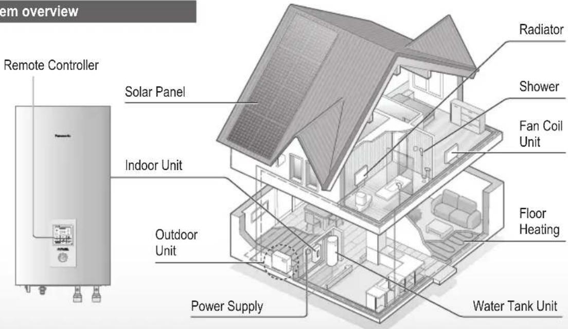
The illustrations in this manual are for explanation purposes only and may differ from the actual unit. They are subject to change without notice for future improvement.
Operating conditions
| HEATING (CIRCUIT) * | 1. *2 COOLING (CIRCUIT) | |
| Water outlet temperature (°C) (Min. / Max.) | 20 / 55 (Below Ambient -15 °C) *320 / 60 (Above Ambient -10 °C) *3 | 5 / 20 |
| Outdoor ambient temperature (°C)(Min. / Max.) | -20 / 35 10 / 43 |
When the outdoor temperature is out of the range in the table, the heating capacity will drop significantly and the outdoor unit may stop operating for its protection.
The unit will restart automatically after the outdoor temperature returns to the specified range.
*3 Between outdoor ambient -10 °C and -15 °C, the water outlet temperature gradually decreases from 60 °C to 55 °C.
To prevent personal injury, injury to others or property damage, please comply with the following:
Incorrect operation due to failure to follow instructions below may cause harm or damage, the seriousness of which is classified as below:
This appliances is not intended for accessibility by the general public.

WARNING
This sign warns of death or serious injury.

CAUTION
This sign warns of injury or damage to property.
The instructions to be followed are classified by the following symbols:

This symbol denotes an action that is PROHIBITED.


These symbols denote actions COMPULSORY.

WARNING
Indoor unit and outdoor unit

This appliance can be used by children aged from 8 years and above and persons with reduced physical, sensory or mental capabilities or lack of experience and knowledge if they have been given supervision or instruction concerning use of the appliance in a safe way and understand the hazards involved. Children shall not play with the appliance. Cleaning and user maintenance shall not be made by children without supervision.
Please consult an authorised dealer or specialist to clean the internal parts, repair, install, remove, disassemble and reinstall the unit. Improper installation and handling will cause leakage, electric shock or fire.
Confirm with authorised dealer or specialist on usage of any specified refrigerant type. Using refrigerant type other than the specified may cause product damage, burst and injury etc.

Do not use means to accelerate the defrosting process or to clean, other than those recommended by manufacturer.
Any unfit method or using incompatible material may cause product damage, burst and serious injury.
Do not install the unit in a potentially explosive or flammable atmosphere. Failure to do so could result in fire.

Do not insert your fingers or other objects into the Air to water indoor or outdoor unit, rotating parts may cause injury.

Do not touch the outdoor unit during lightning, it may cause electric shock.
Do not sit or step on the unit, you may fall down accidentally.

Do not install the indoor unit outdoors. This is designed for indoor installation only.
Power supply

Do not use a modified cord, joint cord, extension cord or unspecified cord to prevent overheating and fire.


To prevent overheating, fire or electric shock:
- Do not share the same power outlet with other equipment.
- Do not operate with wet hands.
- Do not over bend the power supply cord.

If the supply cord is damaged, it must be replaced by the manufacturer, service agent or similarly qualified persons in order to avoid a hazard.
This unit is equipped with Residual Current Circuit Breaker/Earth Leakage Circuit Breaker (RCCB/ELCB). Ask an authorised dealer to check RCCB/ELCB operation regularly, especially after installation, inspection, and maintenance. RCCB/ELCB malfunction may result in electric shock and/or fire.

It is strongly recommended that Install Residual Current Device (RCD) on-site to prevent electric shock and/or fire.
Before obtaining access to terminals, all supply circuits must be disconnected.
Stop using the product if any abnormality/failure occurs and disconnect the power supply. (Risk of smoke/fire/electric shock)
Examples of abnormality/failure
• RCCB/ELCB trips frequently.
- Burning smell is observed.
• Abnormal noise or vibration of the unit is observed.
- Hot water leaks from the indoor unit. Contact your local dealer immediately for maintenance/repair.
Wear gloves during inspection and maintenance.

This equipment must be earthed to prevent electrical shock or fire.

Prevent electric shock by switching off the power supply:
-Before cleaning or servicing, -When extended non-use.
This appliance is for multiple uses. To avoid electric shock, burn and/or fatal injury, make sure to disconnect all power supplies before accessing any terminal in the indoor unit.

CAUTION
Indoor unit and outdoor unit

Do not wash the indoor unit with water, benzine, thinner or scouring powder to avoid damage or corrosion at the unit.
Do not install the unit close to any combustibles or at bathroom. Otherwise, it may cause electric shock and/or fire.
Do not touch the sharp aluminium fin, sharp parts may cause injury.

Do not use the system during sterilisation in order to prevent scalding with hot water, or overheating of shower.
Do not dismantle the unit for cleaning purpose to avoid injury.
Do not step onto an unstable bench when cleaning the unit to avoid injury.
Do not place a vase or water container on the unit. Water may enter the unit and degrade the insulation. This may cause an electric shock.

Prevent water leakage by ensuring drainage pipe is:
-Connected properly,
-Kept clear of gutters and containers, or
-Not immersed in water
After a long period of use or use with any combustible equipment, aerate the room regularly.
After a long period of use, make sure the installation rack does not deteriorate to prevent the unit from falling down.
Remote Controller

Do not wet the Remote Controller. Failure to do so may result in electric shock and/or fire.
Do not press the buttons on the Remote Controller using hard and sharp objects. Failure to do so may cause damage to the unit.
Do not wash the Remote Controller using water, benzine, thinner or scouring powder.
Do not inspect or maintain the Remote Controller by yourself. Consult an authorised dealer in order to prevent personal injury caused by incorrect operation.

WARNING
This appliance is filled with R32 (mild flammable refrigerant).
If the refrigerant is leaked and exposed to an external ignition source, there is a risk of fire.
Indoor unit and outdoor unit

The appliance shall be installed, and/or operated in a room with floor area larger than Amin (m²) and keep away from ignition sources, such as heat/sparks/open flame or hazardous areas such as gas appliances, gas cooking, reticulated gas supply systems or electric cooking appliances, etc. (Refer to Table I of Installation instructions table for Amin (m²))
Be aware that refrigerant may not contain an odour, highly recommended to ensure suitable flammable refrigerant gas detectors are present, operating and able to warn of a leak.
Keep any required ventilation openings clear of obstruction.

Do not pierce or burn as the appliance is pressurized. Do not expose the appliance to heat, flame, sparks, or other sources of ignition. Else it may explode and cause injury or death.
Precaution for using R32 refrigerant
The basic installation work procedures are the same as conventional refrigerant (R410A, R22) models.

Since the working pressure is higher than that of refrigerant R22 models, some of the piping and installation and service tools are special. Especially, when replacing a refrigerant R22 model with a new refrigerant R32 model, always replace the conventional piping and flare nuts with the R32 and R410A piping and flare nuts on the outdoor unit side. For R32 and R410A, the same flare nut on the outdoor unit side and pipe can be used.
The mixing of different refrigerants within a system is prohibited. Models that use refrigerant R32 and R410A have a different charging port thread diameter to prevent erroneous charging with refrigerant R22 and for safety.
Therefore, check beforehand. [The charging port thread diameter for R32 and R410A is 1/2 inch.]
Must always ensure that foreign matter (oil, water, etc.) does not enter the piping. Also, when storing the piping, securely seal the opening by pinching, taping, etc. (Handling of R32 is similar to R410A.)
• Operation, maintenance, repairing and refrigerant recovery should be carried out by trained and certified personnel in the use of flammable refrigerants and as recommended by the manufacturer. Any personnel conducting an operation, servicing or maintenance on a system or associated parts of the equipment should be trained and certified.

- Any part of refrigerating circuit (evaporators, air coolers, AHU, condensers or liquid receivers) or piping should not be located in the proximity of heat sources, open flames, operating gas appliance or an operating electric heater.
- The user/owner or their authorised representative shall regularly check the alarms, mechanical ventilation and detectors, at least once a year, where as required by national regulations, to ensure their correct functioning.
- A logbook shall be maintained. The results of these checks shall be recorded in the logbook.
• In case of ventilations in occupied spaces shall be checked to confirm no obstruction.
- Before a new refrigerating system is put into service, the person responsible for placing the system in operation should ensure that trained and certified operating personnel are instructed on the basis of the instruction manual about the construction, supervision, operation and maintenance of the refrigerating system, as well as the safety measures to be observed, and the properties and handling of the refrigerant used.
• The general requirement of trained and certified personnel are indicated as below:
a) Knowledge of legislation, regulations and standards relating to flammable refrigerants; and,
b) Detailed knowledge of and skills in handling flammable refrigerants, personal protective equipment, refrigerant leakage prevention, handling of cylinders, charging, leak detection, recovery and disposal; and,

c) Able to understand and to apply in practice the requirements in the national legislation, regulations and Standards; and,
d) Continuously undergo regular and further training to maintain this expertise.
e) Air-conditioner piping in the occupied space shall be installed in such a way to protect against accidental damage in operation and service.
f) Precautions shall be taken to avoid excessive vibration or pulsation to refrigerating piping.
g) Ensure protection devices, refrigerating piping and fittings are well protected against adverse environmental effects (such as the danger of water collecting and freezing in relief pipes or the accumulation of dirt and debris).
h) Expansion and contraction of long runs piping in refrigerating systems shall be designed and installed securely (mounted and guarded) to minimize the likelihood hydraulic shock damaging the system.
i) Protect the refrigerating system from accidental rupture due to moving furniture or reconstruction activities.
j) To ensure no leaking, field-made refrigerant joints indoors shall be tightness tested. The test method shall have a sensitivity of 5 grams per year of refrigerant or better under a pressure of at least 0.25 times the maximum allowable pressure (>1.04 MPa, max 4.15 MPa). No leak shall be detected.

1. Installation (Space)
- Product with flammable refrigerants, shall be installed according to the minimum room area, Amin (m ^2 ) mentioned in Table I of the Installation Instructions.
- In case of field charge, the effect on refrigerant charge caused by the different pipe length has to be quantified, measured and labelled.
- Must ensure the installation of pipework shall be kept to a minimum. Avoid use dented pipe and do not allow acute bending.
- Must ensure that pipe-work shall be protected from physical damage.
- Must comply with national gas regulations, state municipal rules and legislation. Notify relevant authorities in accordance with all applicable regulations.
- Must ensure mechanical connections be accessible for maintenance purposes.
• In cases that require mechanical ventilation, ventilation openings shall be kept clear of obstruction. - When disposal of the product, do follow to the precautions in #12 and comply with national regulations. Always contact to local municipal offices for proper handling.

2.Servicing
2-1. Service personnel
- The system is inspected, regularly supervised and maintained by a trained and certified service personnel who is employed by the person user or party responsible.
- Ensure the actual refrigerant charge is in accordance with the room size within which the refrigerant containing parts are installed.
- Ensure refrigerant charge not to leak.
- Any qualified person who is involved with working on or breaking into a refrigerant circuit should hold a current valid certificate from an industry-accredited assessment authority, which authorizes their competence to handle refrigerants safely in accordance with an industry recognised assessment specification.
- Servicing shall only be performed as recommended by the equipment manufacturer. Maintenance and repair requiring the assistance of other skilled personnel shall be carried out under the supervision of the person competent in the use of flammable refrigerants.
• Servicing shall be performed only as recommended by the manufacturer.

2-2.Work
- Prior to beginning work on systems containing flammable refrigerants, safety checks are necessary to ensure that the risk of ignition is minimised. For repair to the refrigerating system, the precautions in #2-2 to #2-8 must be followed before conducting work on the system.
• Work shall be undertaken under a controlled procedure so as to minimize the risk of a flammable gas or vapour being present while the work is being performed. - All maintenance staff and others working in the local area shall be instructed and supervised on the nature of work being carried out.
- Avoid working in confined spaces. Always ensure away from source, at least 2 meter of safety distance, or zoning of free space area of at least 2 meter in radius.
- Wear appropriate protective equipment, including respiratory protection, as conditions warrant.
- Keep all sources of ignition and hot metal surfaces away.

2-3. Checking for presence of refrigerant
• The area shall be checked with an appropriate refrigerant detector prior to and during work, to ensure the technician is aware of potentially flammable atmospheres.
- Ensure that the leak detection equipment being used is suitable for use with flammable refrigerants, i.e. non sparking, adequately sealed or intrinsically safe.
• In case of leakage/spillage happened, immediately ventilate area and stay upwind and away from spill/release.
• In case of leakage/spillage happened, do notify persons down wind of the leaking/spill, isolate immediate hazard area and keep unauthorized personnel out.

2-4. Presence of fire extinguisher
- If any hot work is to be conducted on the refrigerating equipment or any associated parts, appropriate fire extinguishing equipment shall be available at hand.
- Have a dry powder or CO_2 fire extinguisher adjacent to the charging area.

2-5. No ignition sources
- No person carrying out work in relation to a refrigerating system which involves exposing any pipe work that contains or has contained flammable refrigerant shall use any sources of ignition in such a manner that it may lead to the risk of fire or explosion. He/She must not be smoking when carrying out such work.
- All possible ignition sources, including cigarette smoking, should be kept sufficiently far away from the site of installation, repairing, removing and disposal, during which flammable refrigerant can possibly be released to the surrounding space.
- Prior to work taking place, the area around the equipment is to be surveyed to make sure that there are no flammable hazards or ignition risks.
- "No Smoking" signs shall be displayed.

2-6. Ventilated area
- Ensure that the area is in the open or that it is adequately ventilated before breaking into the system or conducting any hot work.
- A degree of ventilation shall continue during the period that the work is carried out.
• The ventilation should safely disperse any released refrigerant and preferably expel it externally into the atmosphere.

2-7. Checks to the refrigerating equipment
- Where electrical components are being changed, they shall be fit for the purpose and to the correct specification.
- At all times the manufacturer's maintenance and service guidelines shall be followed.
- If in doubt consult the manufacturer's technical department for assistance.
• The following checks shall be applied to installations using flammable refrigerants.
-The actual refrigerant charge is in accordance with the room size within which the refrigerant containing parts are installed.
-The ventilation machinery and outlets are operating adequately and are not obstructed.
-If an indirect refrigerating circuit is being used, the secondary circuit shall be checked for the presence of refrigerant.
-Marking to the equipment continues to be visible and legible. Markings and signs that are illegible shall be corrected.
-Refrigerating pipe or components are installed in a position where they are unlikely to be exposed to any substance which may corrode refrigerant containing components, unless the components are constructed of materials which are inherently resistant to being corroded or are properly protected against being so corroded.

2-8. Checks to electrical devices
• Repair and maintenance to electrical components shall include initial safety checks and component inspection procedures.
- Initial safety checks shall include but not limit to:-
-That capacitors are discharged: this shall be done in a safe manner to avoid possibility of sparking.
-That there no live electrical components and wiring are exposed while charging, recovering or purging the system.
-That there is continuity of earth bonding.
- At all times the manufacturer's maintenance and service guidelines shall be followed.
- If in doubt consult the manufacturer's technical department for assistance.
- If a fault exists that could compromise safety, then no electrical supply shall be connected to the circuit until it is satisfactorily dealt with.
- If the fault cannot be corrected immediately but it is necessary to continue operation, an adequate temporary solution shall be used.
- The owner of the equipment must be informed or reported so all parties are advised thereinafter.

3. Repairs to sealed components
- During repairs to sealed components, all electrical supplies shall be disconnected from the equipment being worked upon prior to any removal of sealed covers, etc.
- If it is absolutely necessary to have an electrical supply to equipment during servicing, then a permanently operating form of leak detection shall be located at the most critical point to warn of a potentially hazardous situation.
- Particular attention shall be paid to the following to ensure that by working on electrical components, the casing is not altered in such a way that the level of protection is affected. This shall include damage to cables, excessive number of connections, terminals not made to original specification, damage to seals, incorrect fitting of glands, etc.
- Ensure that apparatus is mounted securely.
- Ensure that seals or sealing materials have not degraded such that they no longer serve the purpose of preventing the ingress of flammable atmospheres.
- Replacement parts shall be in accordance with the manufacturer's specifications.
NOTE: The use of silicon sealant may inhibit the effectiveness of some types of leak detection equipment.
Intrinsically safe components do not have to be isolated prior to working on them.

4. Repair to intrinsically safe components
- Do not apply any permanent inductive or capacitance loads to the circuit without ensuring that this will not exceed the permissible voltage and current permitted for the equipment in use.
- Intrinsically safe components are the only types that can be worked on while live in the presence of a flammable atmosphere.
• The test apparatus shall be at the correct rating. - Replace components only with parts specified by the manufacturer. Unspecified parts by manufacturer may result ignition of refrigerant in the atmosphere from a leak.

5. Cabling
- Check that cabling will not be subject to wear, corrosion, excessive pressure, vibration, sharp edges or any other adverse environmental effects.
- The check shall also take into account the effects of aging or continual vibration from sources such as compressors or fans.

6. Detection of flammable refrigerants
• Under no circumstances shall potential sources of ignition be used in the searching or detection of refrigerant leaks.
- A halide torch (or any other detector using a naked flame) shall not be used.

7. The following leak detection methods are deemed acceptable for all refrigerant systems
- No leaks shall be detected when using detection equipment with a sensitivity of 5 grams per year of refrigerant or better under a pressure of at least 0.25 times the maximum allowable pressure (>1.04 MPa, max 4.15 MPa), for example, a universal sniffer.
- Electronic leak detectors may be used to detect flammable refrigerants, but the sensitivity may not be adequate, or may need recalibration. (Detection equipment shall be calibrated in a refrigerant-free area.)
- Ensure that the detector is not a potential source of ignition and is suitable for the refrigerant used.
- Leak detection equipment shall be set at a percentage of the LFL of the refrigerant and shall be calibrated to the refrigerant employed and the appropriate percentage of gas (25 % maximum) is confirmed.
- Leak detection fluids are also suitable for use with most refrigerants, for example, bubble method and fluorescent method agents. The use of detergents containing chlorine shall be avoided as the chlorine may react with the refrigerant and corrode the copper pipe-work.
- If a leak is suspected, all naked flames shall be removed/extinguished.
- If a leakage of refrigerant is found which requires brazing, all of the refrigerant shall be recovered from the system, or isolated (by means of shut off valves) in a part of the system remote from the leak. The precautions in #8 must be followed to remove the refrigerant.

8. Removal and evacuation
- When breaking into the refrigerant circuit to make repairs – or for any other purpose – conventional procedures shall be used. However, it is important that best practice is followed since flammability is a consideration. The following procedure shall be adhered to: remove refrigerant -> purge the circuit with inert gas -> evacuate -> purge with inert gas -> open the circuit by cutting or brazing.
• The refrigerant charge shall be recovered into the correct recovery cylinders. - The system shall be purged with OFN to render the appliance safe.
• This process may need to be repeated several times. - Compressed air or oxygen shall not be used for this task.
- Purging shall be achieved by breaking the vacuum in the system with OFN and continuing to fill until the working pressure is achieved, then venting to atmosphere, and finally pulling down to a vacuum.
• This process shall be repeated until no refrigerant is within the system. - When the final OFN charge is used, the system shall be vented down to atmospheric pressure to enable work to take place.
- This operation is absolutely vital if brazing operations on the pipe work are to take place.
- Ensure that the outlet for the vacuum pump is not close to any potential ignition sources and there is ventilation available.
OFN = oxygen free nitrogen, type of inert gas.

9. Charging procedures
• In addition to conventional charging procedures, the following requirements shall be followed.
-Ensure that contamination of different refrigerants does not occur when using charging equipment.
-Hoses or lines shall be as short as possible to minimize the amount of refrigerant contained in them.
-Cylinders shall be kept in an appropriate position according to the instructions.
-Ensure that the refrigerating system is earthed prior to charging the system with refrigerant.
-Label the system when charging is complete (if not already).
-Extreme care shall be taken not to over fill the refrigerating system.
- Prior to recharging the system it shall be pressure tested with OFN (refer to #7).
- The system shall be leak tested on completion of charging but prior to commissioning.
• A follow up leak test shall be carried out prior to leaving the site. - Electrostatic charge may accumulate and create a hazardous condition when charging and discharging the refrigerant. To avoid fire or explosion, dissipate static electricity during transfer by grounding and bonding containers and equipment before charging/discharging.

10. Decommissioning
- Before carrying out this procedure, it is essential that the technician is completely familiar with the equipment and all its details.
- It is recommended good practice that all refrigerants are recovered safely.
- Prior to the task being carried out, an oil and refrigerant sample shall be taken in case analysis is required prior to re-use of recovered refrigerant.
- It is essential that electrical power is available before the task is commenced.
a) Become familiar with the equipment and its operation.
b) Isolate system electrically.
c) Before attempting the procedure ensure that:
- mechanical handling equipment is available, if required, for handling refrigerant cylinders;
- all personal protective equipment is available and being used correctly;
• the recovery process is supervised at all times by a competent person;
• recovery equipment and cylinders conform to the appropriate standards.
d) Pump down refrigerant system, if possible.
e) If a vacuum is not possible, make a manifold so that refrigerant can be removed from various parts of the system.
f) Make sure that cylinder is situated on the scales before recovery takes place.
g) Start the recovery machine and operate in accordance with instructions.

h) Do not over fill cylinders. (No more than 80 % volume liquid charge).
i) Do not exceed the maximum working pressure of the cylinder, even temporarily.
j) When the cylinders have been filled correctly and the process completed, make sure that the cylinders and the equipment are removed from site promptly and all isolation valves on the equipment are closed off.
k) Recovered refrigerant shall not be charged into another refrigerating system unless it has been cleaned and checked.
- Electrostatic charge may accumulate and create a hazardous condition when charging or discharging the refrigerant. To avoid fire or explosion, dissipate static electricity during transfer by grounding and bonding containers and equipment before charging/discharging.

11. Labelling
• Equipment shall be labelled stating that it has been de-commissioned and emptied of refrigerant.
• The label shall be dated and signed.
- Ensure that there are labels on the equipment stating the equipment contains flammable refrigerant.

12. Recovery
- When removing refrigerant from a system, either for servicing or decommissioning, it is recommended good practice that all refrigerants are removed safely.
- When transferring refrigerant into cylinders, ensure that only appropriate refrigerant recovery cylinders are employed.
- Ensure that the correct number of cylinders for holding the total system charge are available.
- All cylinders to be used are designated for the recovered refrigerant and labelled for that refrigerant (i.e. special cylinders for the recovery of refrigerant).
- Cylinders shall be complete with pressure relief valve and associated shut-off valves in good working order.
- Recovery cylinders are evacuated and, if possible, cooled before recovery occurs.
• The recovery equipment shall be in good working order with a set of instructions concerning the equipment that is at hand and shall be suitable for the recovery of flammable refrigerants.
• In addition, a set of calibrated weighing scales shall be available and in good working order.
- Hoses shall be complete with leak-free disconnect couplings and in good condition.
- Before using the recovery machine, check that it is in satisfactory working order, has been properly maintained and that any associated electrical components are sealed to prevent ignition in the event of a refrigerant release. Consult manufacturer if in doubt.

- The recovered refrigerant shall be returned to the refrigerant supplier in the correct recovery cylinder, and the relevant Waste Transfer Note arranged.
- Do not mix refrigerants in recovery units and especially not in cylinders.
- If compressors or compressor oils are to be removed, ensure that they have been evacuated to an acceptable level to make certain that flammable refrigerant does not remain within the lubricant.
• The evacuation process shall be carried out prior to returning the compressor to the suppliers.
- Only electric heating to the compressor body shall be employed to accelerate this process.
- When oil is drained from a system, it shall be carried out safely.
Buttons / Indicator
Quick Menu button
① (For more details, refer to the separate Quick Menu Guide.)
② Back button
Returns to the previous screen
③LCD Display
④ Main Menu button For function setup
⑤ ON/OFF button
Starts/Stops operation
Operation indicator
⑥ Illuminates during operation, blinks during alarm.
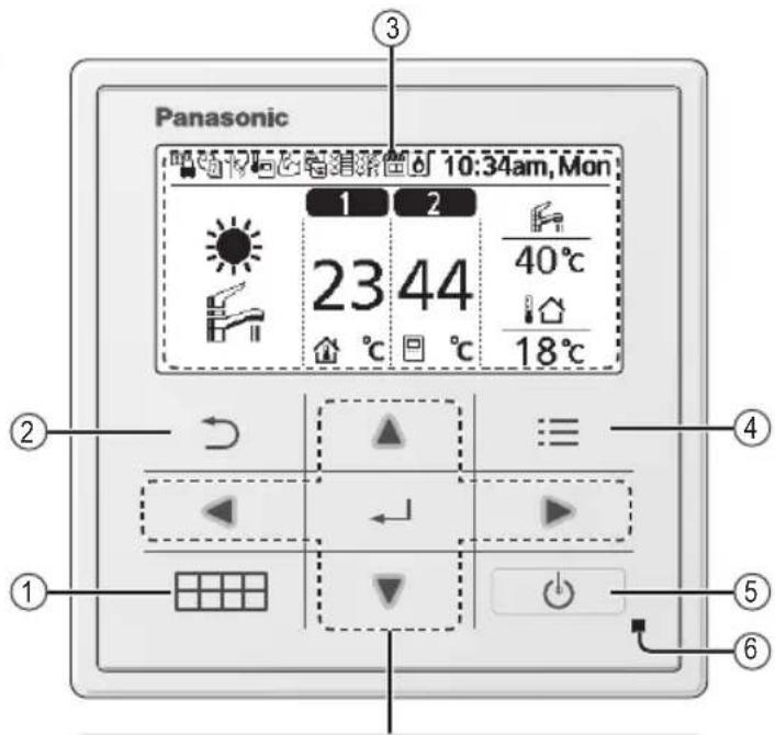
Cross key buttons
Selects an item.
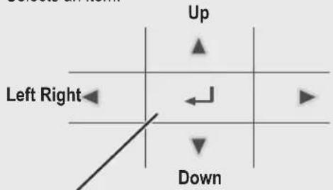
Enter button
Fixes the selected content.

Press centre

No glove
natural_image
Hand pointing at a grid with directional arrows (no text or symbols)
No pen
natural_image
Hand holding a pen writing on a grid, no text or symbols presentRemote Controller buttons and display
Display
① Mode selection
flowchart
graph TD
    A["HOAT + TANK"] --> B["HEAT"]
    B --> C["HEAT + AUTO"]
    D["COOL + TANK"] --> E["COOL operation is either turned ON or OFF."]
    E --> F["The outdoor unit provides cooling to the system."]
    G["TANK"] --> H["The outdoor unit provides cooling to the system."]
    H --> I["The outdoor unit provides heating when boiling tank."]
    J["HEAT + TANK"] --> K["HEAT operation is either turned ON or OFF."]
    K --> L["The outdoor unit provides heat to the system."]
    M["COOL + TANK"] --> N["COOL operation is either turned ON or OFF."]
    N --> O["The outdoor unit provides cooling to the system."]
    P["HEAT + TANK"] --> Q["HEAT operation is either turned ON or OFF."]
    Q --> R["The outdoor unit provides heat to the system."]
    S["COOL + TANK"] --> T["COOL operation is either turned ON or OFF."]
    T --> U["The outdoor unit provides cooling to the system."]
    V["HEAT + TANK"] --> W["HEAT operation is either turned ON or OFF."]
    W --> X["The outdoor unit provides heat to the system."]
    Y["COOL + TANK"] --> Z["COOL operation is either turned ON or OFF."]
    Z --> AA["The outdoor unit provides cooling to the system."]
    AB["HEAT + TANK"] --> AC["HEAT operation is either turned ON or OFF."]
    AC --> AD["The outdoor unit provides heat to the system."]
    AE["COOL + TANK"] --> AF["COOL operation is either turned ON or OFF."]
    AF --> AG["The outdoor unit provides cooling to the system."]
    AH["HEAT + TANK"] --> AI["HEAT operation is either turned ON or OFF."]
    AI --> AJ["The outdoor unit provides heat to the system."]
    AK["COOL + TANK"] --> AL["COOL operation is either turned ON or OFF."]
    AL --> AM["The outdoor unit provides cooling to the system."]
    AN["HEAT + TANK"] --> AO["HEAT operation is either turned ON or OFF."]
    AO --> AP["The outdoor unit provides heat to the system."]
    AQ["COOL + TANK"] --> AR["COOL operation is either turned ON or OFF."]
    AR --> AS["The outdoor unit provides cooling to the system."]
    AT["HEAT + TANK"] --> AU["HEAT operation is either turned ON or OFF."]
    AU --> AV["The outdoor unit provides heat to the system."]
    AW["COOL + TANK"] --> AX["COOL operation is either turned ON or OFF."]
    AX --> AY["The outdoor unit provides cooling to the system."]
    AZ["HEAT + TANK"] --> BA["HEAT operation is either turned ON or OFF."]
    BA --> BB["The outdoor unit provides heat to the system."]
    BC["COOL + TANK"] --> BD["COOL operation is either turned ON or OFF."]
    BD --> BE["The outdoor unit provides cooling to the system."]
    BF["HEAT + TANK"] --> BG["HEAT operation is either turned ON or OFF."]
    BG --> BH["The outdoor unit provides heat to the system."]
    BI["COOL + TANK"] --> BJ["COOL operation is either turned ON or OFF."]
    BJ --> BK["The outdoor unit provides cooling to the system."]
    BL["HEAT + TANK"] --> BM["HEAT operation is either turned ON or OFF."]
    BM --> BN["The outdoor unit provides heat to the system."]
    BO["COOL + TANK"] --> BP["COOL operation is either turned ON or OFF."]
    BP --> BQ["The outdoor unit provides cooling to the system."]
    BR["HEAT + TANK"] --> BS["HEAT operation is either turned ON or OFF."]
    BS --> BT["The outdoor unit provides heat to the system."]
    BU["COOL + TANK"] --> BV["COOL operation is either turned ON or OFF."]
    BV --> BW["The outdoor unit provides cooling to the system."]
    BX["HEAT + TANK"] --> BY["HEAT operation is either turned ON or OFF."]
    BY --> BZ["The outdoor unit provides heat to the system."]
    CA["COOL + TANK"] --> CB["COOL operation is either turned ON or OFF."]
    CB --> CC["The outdoor unit provides cooling to the system."]
    CD["TANK"] --> CE["TANK operation is either turned ON or OFF."]
    CE --> CF["The outdoor unit provides cooling to the system."]
    CG["TANK + TANK"] --> CH["TANK operation is either turned ON or OFF."]
    CH --> CI["The outdoor unit provides cooling to the system."]
    CJ["TANK + TANK"] --> CK["TANK operation is either turned ON or OFF."]
    CK --> CL["The outdoor unit provides cooling to the system."]
    CM["TANK + TANK"] --> CN["TANK operation is either turned ON or OFF."]
    CN --> CO["TANK operation provides cooling to the system."]
    CP["TANK + TANK"] --> CQ["TANK operation is either turned ON or OFF."]
    CQ --> CR["TANK operation provides cooling to the system."]
    CS["TANK + TANK"] --> CT["TANK operation is either turned ON or OFF."]
    CT --> CU["TANK operation provides cooling to the system."]
    CV["TANK + TANK"] --> CW["TANK operation is either turned ON or OFF."]
    CW --> CX["TANK operation provides cooling to the system."]
② Operation icons
The status of operation is displayed.
Icon will not display (under operation OFF screen) whenever operation is OFF except weekly timer.


Holiday operation status Weekly Upper operation status Quiet operation status
Zone: Room Thermostat →Internal sensor status
Room Heater status Tank Heater status Solar status
Bivalent status (Boiler)


Demand Control or SG ready or SHP status
The system is locked to operate without COOL mode. It can be unlocked only by authorised installers or our authorised service partners.
Only displayed when COOL mode is unlocked (This means when COOL mode is available).
③ Temperature of each zone
④ Time and day
⑤Water Tank temperature
⑥ Outdoor temperature
⑦ Sensor type/Set temperature type icons

Water Temperature →Compensation curve Room Thermostat →External

Water Temperature →Direct Room Thermostat →Internal

Pool only Room Thermistor
Initialization
Before starting to install the various menu settings, please initiate the Remote Controller by selecting the language of operation and installing the date and time correctly.
When power is turned on for the first time, it becomes the setting screen automatically. It can also be set from personal setting of the menu.
Selecting the language
Wait while the display is initializing.
When initializing screen ends, it turns to normal screen.
When any button is pressed, language setting screen appears.
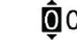
① Scroll with ▼ and ▲ to select the language.
② Press ← to confirm the selection.
Setting the clock
① Selectwith ▼ or ▲ how to display the time, either 24h or am/pm format (for example, 15:00 or 3:00 pm).
② Press ← to confirm the selection.
③ Use ▼ and to select year, month, day, hour and minutes. (Select and move with ▼ and press to confirm.)
④ Once the time is set, time and day will appear on the display even if the Remote Controller is turned OFF.
![Initialization 12:00am, Mon LCD blinking Initializing . . . 12:00am, Mon [◀] Start Language 12:00am, Mon ENGLISH FRANÇAIS DEUTSCH ITALIANO Select [←] Confirm Clock format 12:00am, Mon 24h am/pm *Select [←] Confirm Date & Time 12:00am, Mon Year/Month/Day Hour : Min 2015 / 01 / 01 12 : 00 am *Select [←] Confirm 10:00am, Wed [◀] Start](/content/2026/03/461017/images/76ccdfd21b1944396350ced784d3b71c7a6876c5f44a96bc0d40c3c94b577fc9.jpg)
After the initial settings have been completed, you can select a quick menu from the following options and edit the setting.
① Press ☐ to display the quick menu.
![Select [←] ON/OFF](/content/2026/03/461017/images/a91208f363752512a1d86a9a00fa54e5db89e0196ef1e1ad26f982f5dcafb2d3.jpg)
② Use ▲ ▼ to select menu.
③ Press ← to turn on/off the select menu.
Menus
For user
Select menus and determine settings according to the system available in the household. All initial settings must be done by an authorised dealer or a specialist. It is recommended that all alterations of the initial settings are also done by an authorised dealer or a specialist.
• After initial installation, you may manually adjust the settings.
- The initial setting remains active until the user changes it.
- The Remote Controller can be used for multiple installations.
- Ensure the operation indicator is OFF before setting.
- The system may not work properly if set wrongly. Please consult an authorised dealer.
To display
To select menu: ▲ ▼ ◀ ▶
To confirm the selected content:
![Panasonic Main Menu 10:34am, Mon Function setup System check Personal setup Service contact Select [←] Confirm](/content/2026/03/461017/images/2a4c88e24cdc678ca4e77e4c12e1b5957cbd3d3415f23a5aa113f548eb227fc4.jpg)
Menu Default Setting Setting Options / Display
1 Function setup
1.1 > Weekly timer
Once the weekly timer is set up, User can edit from Quick Menu. To set up to 6 patterns of operation on a daily basis.
- Disabled if Heat-Cool SW is select "Yes" or if Force Heater is on.
Timer setup Select day of the week and set the patterns needed (Time / Operation ON/OFF / Mode)
Timer copy
Select day of the week
| Weekly timer 10:34am,Mon | ||||||
| Sun | Mon | Tue | Wed | Thu | Fri | Sat |
| 1. | 8:00am | ON | 40°C | |||
| 2. | 12:00pm | ON | 24/28°C | 40°C | ||
| 3. | 1:00pm | ON | 12/10°C | |||
| ←Day | Pattern | [-]Edit | ||||
Menu Default Setting Setting Options / Display
1.2 > Holiday timer
To save energy, a holiday period may be set to either turn OFF the system or lower the temperature during the period.
OFF

ON
Holiday start and end. Date and time
OFF or lowered temperature
- Weekly timer setting may be temporarily disabled during Holiday timer setting but it will be restored once the Holiday timer is completed.
Holiday: End 10:34am, Mon
Year/Month/Day Hour:Min

01/07
10:00 am
Select
[←] Confirm
1.3 >Quiet timer
To operate quietly during the preset period. 6 patterns may be set. Level 0 means the mode is off.
Time to start Quiet : Date and time
Level of quietness: 0 \~ 3
| Quiet 10:34am, Mon | ||
| Pattern | Time | Level |
| 1 | 8:00 am | 0 |
| 2 | 5:00 pm | 1 |
| 3 | 11:00 pm | 3 |
| Select | [←] Edit | |
1.4 > Room heater
To set the room heater ON or OFF.

1.5 >Tank heater
To set the tank heater ON or OFF.
OFF

1.6 > Sterilization
To set the auto sterilization ON or OFF.
OFF

- Do not use the system during sterilization in order to prevent scalding with hot water, or overheating of shower.
- Ask an authorised dealer to determine the level of sterilization function field settings according to the local laws and regulations.
Menu Default Setting Setting Options / Display
2 System check
2.1 >Energy monitor
| Present or historical chart of energy consumption, generation or COP. | PresentSelect and retrieve |
| Historical chartSelect and retrieve | |
| ·COP=Coefficient of Performance.·For historical chart, the period is selected from 1 day/1 week/1year.·Energy consumption (kWh) of heating, *1,*2 cooling, tank and total may be retrieved.·The total power consumption is an estimated value based on AC 230 V and may differ from value measured by precise equipment. | |
2.2 > System information
| Shows all system information in each area. | Actual system information of 10 items: Inlet / Outlet / Zone 1 / Zone 2 / Tank / Buffer tank / Solar / Pool / COMP frequency / Pump flowrateSelect and retrieve | System information 10:34am,Mon |
| 1. Inlet : 0°C2. Outlet : 0°C3. Zone 1 : 0°C4. Zone 2 : 0°C | ||
| Page |
2.3 >Error history
| Refer to Troubleshooting for error codes.The most recent error code is displayed at the top. | Select and retrieve | Error history 10:34am, Mon |
| 1. -- | ||
| 2. -- | ||
| 3. -- | ||
| 4. -- | ||
| [--] Clear history |
2.4 > Compressor
| Shows the compressor performance. | Select and retrieve | Compressor 10:34am, Mon |
| 1. Current frequency : 0 Hz2. (OFF-ON) counter : 03. Total ON time : 0 h | ||
| [5]Back |
2.5 > Heater
| Total hours of ON time for Room heater/Tank heater. | Select and retrieve | Heater | 10:34am, Mon |
| Total ON time | |||
| ☐ | : 0h | ||
| ☒ | : 0h | ||
| [☐]Back | |||
3 Personal setup
3.1 > Touch sound
| Turns the operation sound ON/OFF. | ON |
3.2 >LCD contrast
| Sets the screen contrast. | 3 | LCD contrast 10:34am,Mon | ||
| Low | High | |||
| ◄►Select | [←-] Confirm | |||
*1 The system is locked to operate without COOL mode. It can be unlocked only by authorised installers or our authorised service partners.
*2 Only displayed when COOL mode is unlocked (This means when COOL mode is available).
| Menu Default Setting Setting Options / Display | ||||
| 3.3 | >Backlight | |||
| Sets the duration of screen backlight. | 1 min | Backlight 10:34am,Mon | ||
| OFF 5 mins | ||||
| 15 secs 10 mins | ||||
 | ||||
 -]Confirm -]Confirm | ||||
| 3.4 | >Backlight intensity | |||
| Sets screen backlight brightness. | 4 |  ty 10:34am,Mon ty 10:34am,Mon | ||
 Bright Bright | ||||
 -] Confirm -] Confirm | ||||
| 3.5 | >Clock format | |||
| Sets the type of clock display. | 24h |  10:34am,Mon 10:34am,Mon | ||
 4h 4h | ||||
| v/pm | ||||
 -] Confirm -] Confirm | ||||
| 3.6 | >Date & Time | |||
| Sets the present date and time. | Year / Month / Day / Hour / Min |  10:34am,Mon 10:34am,Mon | ||
| Year/Month/Day Hour :Min | ||||
 10 : 00 am 10 : 00 am | ||||
 [-] Confirm [-] Confirm | ||||
| 3.7 | >Language | |||
| Sets the display language for the top screen. | ENGLISH / FRANÇAIS / DEUTSCH / ITALIANO / ESPAÑOL / DANISH / SWEDISH / NORWEGIAN / POLISH / CZECH / NEDERLANDS / TÜRKÇE / SUOMI / MAGYAR / SLOVENŠČINA / HRVATSKI / LIETUVIŲ |  10:34am,Mon 10:34am,Mon | ||
| • For Greek, please refer to the English version. | ENGLISH  | |||
FRANCAS  | ||||
| ITALIANO | ||||
 -] Confirm -] Confirm | ||||
| 3.8 | >Unlock password | |||
| 4 digit password for all the settings. | 0000 |  10:34am,Mon 10:34am,Mon | ||
 00 00 | ||||
 -] Confirm -] Confirm | ||||
| 4 Service contact |  | |||
| 4.1 | >Contact 1 / Contact 2 | |||
| Preset contact number for installer. | Select and retrieve |  10:34am,Mon 10:34am,Mon | ||
Contact 1 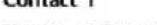 Name : Bryan Adams Name : Bryan Adams | ||||
 345678 345678 | ||||
 | ||||
Menu Default Setting Setting Options / Display
5 Installer setup System setup
5.1 > Optional PCB connectivity
| To connect to the external PCB required for servicing. | No | YesNo |
- If the external PCB is connected (optional), the system will have following additional functions:
① Buffer tank connection and control over its function and temperature.
② Control over 2 zones (including the swimming pool and the function to heat water in it).
③ Solar function (the solar thermal panels connected to either the DHW (Domestic Hot Water) Tank or the Buffer Tank.
• DHW is not applicable for WH-ADC *models.
④ External compressor switch.
⑤ External error signal.
⑥ SG ready control.
⑦ Demand control.
⑧ Heat-Cool SW
5.2 >Zone & Sensor
To select the sensors and to select either 1 zone or 2 zone system. Zone • After selecting 1 or 2 zone system, proceed to the selection of room or swimming pool. Zone & Sensor 10:34am, Mon Zone 1 Zone system
- If the swimming pool is selected, the temperature must be selected for T temperature between 0^ 10^ . 2 Zones system Select [-] Confirm
Sensor * For room thermostat, there is a further selection of external or internal. Sensor Water temperature Room thermostat Room thermistor Select [←] Confirm
5.3 > Heater capacity
To reduce the heater power if unnecessary.* 3 kW / 6 kW / 9kW * Options of kW vary depending on the model. Heater capacity 10:34am, Mon 3 kW [+-] Confirm
5.4 > Anti freezing
To activate or deactivate the water freeze prevention when the system is OFF Yes Yes No
5.5 >Tank connection
To connect tank to the system. No Yes No
5.6 > DHW capacity
To select tank heating capacity to variable or standard. Variable capacity heat up tank with fast mode and keep the tank temperature with efficient mode. While standard capacity heat up Variable
Menu Default Setting Setting Options / Display
| 5.7 | > Buffer tank connection | |||
| To connect tank to the system and if selected YES, to set △T temperature.• The optional PCB connectivity must be selected YES to enable the function.• If the optional PCB connectivity is not selected, the function will not appear on the display. | No |  | ||
| > Yes | ||||
| 5 °C | Set △T for Buffer Tank | Buffer Tank 10:34am, Mon△T for Buffer TankRange: (0°C~10°C)Steps: ±1°C  Select [-]Confirm Select [-]Confirm | ||
| 5.8 | >Tank heater | |||
| To select external or internal tank heater and if External is selected, set a timer for the heater to come on.* This option is available if Tank connection is selected (YES). | Internal | Tank heater 10:34am, MonExternalInternal^Select [-]Confirm | ||
| >External | ||||
| 0:20 | Tank heater ON time set. | Tank heater 10:34am, MonTank heater: ON timeRange: (0:20~3:00)Steps: ±0:05  Select [-]Confirm Select [-]Confirm | ||
| 5.9 | >Base pan heater | |||
| To select whether or not optional base pan heater is connected.* Type A - The base pan heater activates only during deice operation.* Type B -The base pan heater activates when outdoor ambient temperature is 5 °C or lower. | No | YesNo | ||
| >Yes | ||||
| A | Set base pan heater type*. | Base pan heater type 10:34am, Mon| Select [-]Confirm Select [-]Confirm | ||
| 5.10 | >Alternative outdoor sensor | |||
| To select an alternative outdoor sensor. | No |  | ||
| 5.11 | >Bivalent connection | |||
| To select to enable or disable bivalent connection. | No |  | ||
| >Yes | ||||
| To select either auto control pattern or SG ready input control pattern.* This selection only displays to select when optional pcb connection set to Yes. | Auto | 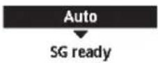 | ||
Menu Default Setting Setting Options / Display
| To select a bivalent connection to allow an additional heat source such as a boiler to heat-up the buffer tank and domestic hot water tank when heatpump capacity is insufficient at low outdoor temperature. The bivalent feature can be set-up either in alternative mode (heatpump and boiler operate alternately), or in parallel mode (both heatpump and boiler operate simultaneously), or in advance parallel mode (heatpump operates and boiler turns on for buffer-tank and/or domestic hot water depending on the control pattern setting options). | >Yes >Auto | ||
| -5°C | Set outdoor temperature for turn ON Bivalent connection. | Bivalent connection 10:34am, MonTurn ON: Outdoor tempRange: (-15°C~35°C)Steps: ±1°C  Select [-] Confirm Select [-] Confirm | |
| Yes >After selecting the outdoor temperature | |||
| Control pattern | Bivalent connection 10:34am, MonControl patternAlternativeParallelAdvanced parallelSelect [-] Confirm | ||
| Alternative / Parallel / Advanced parallel | |||
| • Select advanced parallel for bivalent use of the tanks. | |||
| Control pattern >Alternative | |||
| OFF | Option to set external pump either ON or OFF during bivalent operation. Set to ON if system is simple bivalent connection. | Bivalent connection 10:34am, MonExternal pumpONOFFSelect [-] Confirm | |
| Control pattern >Advanced parallel | |||
| Heat Selection of the tank | Bivalent connection 10:34am, MonAdvanced parallelHeatDHWSelect [-] Confirm | ||
| • “Heat” implies Buffer Tank and “DHW” implies Domestic Hot Water Tank. | |||
| Control pattern >Advanced parallel >Heat Yes | |||
| • Buffer Tank is activated only after selecting “Yes”. | Bivalent connection 10:34am, MonAdvanced parallel: HeatYesNoSelect [-] Confirm | ||
| -8°C | Set the temperature threshold to start the bivalent heat source. | Bivalent connection 10:34am, MonHeat start: Target temp.Range: (-10°C~0°C)Steps: ±1°C  Select [-] Confirm Select [-] Confirm | |
| 0:30 | Delay timer to start the bivalent heat source(in hour and minutes). | Bivalent connection 10:34am, MonHeat start: Delay timeRange: (0:00~1:30)Steps: ±0:05  Select [-] Confirm Select [-] Confirm | |
| -2°C | Set the temperature threshold to stop the bivalent heat source. | Bivalent connection 10:34am, MonHeat stop: Target temp.Range: (-10°C~0°C)Steps: ±1°C  Select [-] Confirm Select [-] Confirm | |
| Menu Default Setting Setting Options / Display | |||
| 0:30 | Delay timer to stop the bivalent heat source (in hour and minutes). | Bivalent connection 10:34am, Mon Heat stop: Delay time Range: (0:00-1:30) Steps: ±0:05 Select [-] Confirm | |
| Control pattern >Advanced parallel >DHW Yes | |||
| • DHW Tank is activated only after selecting "Yes". | Bivalent connection 10:34am, Mon Advanced parallel: DHW Yes No Select [-] Confirm | ||
| 0:30 | Delay timer to start the bivalent heat source (in hour and minutes). | Bivalent connection 10:34am, Mon DHW: Delay time Range: (0:30-1:30) Steps: ±0:05 Select [-] Confirm | |
| SG ready input control for bivalent system follow below input condition. | >Yes >SG ready | ||
| SG signal Operation pattern | Option to set external pump either ON or OFF during bivalent operation. Set to ON if system is simple bivalent connection. Bivalent connection 10:34am, Mon External pump ON OFF Select [-] Confirm | ||
| Vcc-bit1 Vcc-bit2 | |||
| Open Open | Heat Pump OFF, Boiler OFF | ||
| Short Open | Heat Pump ON, Boiler OFF | ||
| Open Short | Heat Pump OFF, Boiler ON | ||
| Short Short | Heat Pump ON, Boiler ON | ||
| 5.12 >External SW | |||
| No | Yes No | ||
| 5.13 >Solar connection | |||
| • The optional PCB connectivity must be selected YES to enable the function.• If the optional PCB connectivity is not selected, the function will not appear on the display.• DHW is not applicable for WH-ADC *models. | No | Yes No | |
| >Yes | |||
| Buffer tank Selection of the tank | Solar connection 10:34am, Mon Buffer tank DHW tank Select [-] Confirm | ||
| >Yes >After selecting the tank | |||
| 10 °C | Set △T ON temperature | Solar connection 10:34am, Mon ΔT Turn ON Range: (6°C~15°C) Steps: ±1°C Select [-] Confirm | |
Menu Default Setting Setting Options / Display
| >Yes >After selecting the tank >T.ON temperature | |||
| 5°C | Set △OFFtemperature | Solar connection 10:34am, Mon△T Turn OFFRange: (2°C~9°C)Steps: ±1°C  Select [-] Confirm Select [-] Confirm | |
| >Yes >After selecting the tank >T.ON temperature T QFF temperature | |||
| 5°C | Set Antifreeze temperature | Solar connection 10:34am, MonAnti freezeRange: (-20°C~10°C)Steps: ±1°C  Select [-] Confirm Select [-] Confirm | |
| >Yes >After selecting the tank >T.ON temperature T QFF temperature> After setting the antifreeze temperature | |||
| 80°C Set Hi limit | 80°C Set Hi limit | Solar connection 10:34am, MonHi limitRange: (70°C~90°C)Steps: ±5°C  Select [-] Confirm Select [-] Confirm | |
| 5.14 >External error signal | |||
| No |  | ||
| 5.15 >Demand control | |||
| No |  | ||
| 5.16 >SG ready | |||
| No |  | ||
| >Yes | |||
| 120% | Capacity (1) & (2)of DHW (in %),Heat (in %) andCool (in °C) | SG ready 10:34am, MonCapacity [1-0]: DHWRange: (50%~150%)Steps: ±5%  Select [-] Confirm Select [-] Confirm | |
| 5.17 >External compressor SW | |||
| No |  | ||
| 5.18 >Circulation liquid | |||
| To select whether to circulate water or glycol in the system. | Water | Circulation liquid 10:34am, Mon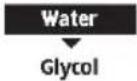 Select [-] Confirm Select [-] Confirm | |
| Menu Default Setting Setting Options / Display | ||
| 5.19 > Heat-Cool SW | ||
| No | YesNo | |
| 5.20 > Force heater | ||
| To turn on Force heater either manually (by default) or automatically. | Manual | Force heater 10:34am,MonAutoManual |
| Select [-] Confirm | ||
| 5.21 > Force defrost | ||
| If auto selection is set, outdoor unit will start defrost operation if long heating hour operate during low outdoor temperature. | Manual | AutoManual |
| 5.22 > Defrost signal | ||
| To turn on defrost signal to stop fan coil during defrost operation. (If defrost signal set to yes, bivalent function will not available to use) | No | YesNo |
| 5.23 > Pump flowrate | ||
| To set variable flow pump control or fix pump duty control. | T | T Max. Duty |
| 6 Installer setup >Operation setup | |||
| To access to the four major functions or modes. | 4 main modes | Operation setup 10:34am,Mon | |
| Heat | |||
| Cool | |||
| Auto | |||
| Tank | |||
| Select [←] Confirm | |||
| 6.1 > Heat | |||
| To set various water & ambient temperatures for heating. | Water temp. for heating ON / Outdoor temp. for heating OFF / △T for heating ON / Heater ON/OFF | Operation setup 10:34am,Mon | |
| Heat | |||
| Water temp. for heating ON | |||
| Outdoor temp. for heating OFF | |||
| △T for heating ON | |||
| Select [←] Confirm | |||
| > Water temp. for heating ON | |||
| Compensation curve | Heating ON temperatures in compensation curve or direct input. | Operation setup 10:34am,Mon | |
| Heat ON: Water temp. | |||
| Compensation curve | |||
| Direct | |||
| Select [←] Confirm | |||
*1 The system is locked to operate without COOL mode. It can be unlocked only by authorised installers or our authorised service partners.
*2 Only displayed when COOL mode is unlocked (This means when COOL mode is available).
Menu Default Setting Setting Options / Display
| >Water temp. for heating ON >Compensation curve | ||
| X axis: -5 °C, 15 °CY axis: 55 °C, 35 °C | Input the 4 temperature points(2 on horizontal Xaxis, 2 on vertical Yaxis). | Heat ON: Water temp.:Zone1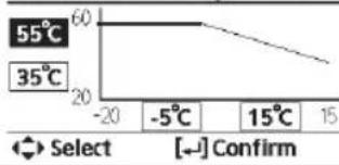 |
| • Temperature range: X axis: -20 °C ~ 15 °C, Y axis: See below• Temperature range for the Y axis input:1. WH-UD model: 20 °C ~ 60 °C2. WH-UH model & Back up heater is enabled: 25 °C ~ 65 °C3. WH-UH model & Back up heater is disabled: 35 °C ~ 65 °C4. WH-UX model: 20 °C ~ 60 °C• If 2 zone system is selected, the 4 temperature points must also be input for Zone 2.• “Zone 1” and “Zone 2” will not appear on the display if only 1 zone system. | ||
| >Water temp. for heating ON >Direct | ||
| 35 °C | Temperature forheating ON | Operation setup 10:34am,MonHeat ON: Water temp.:Zone2Range: (20°C~60°C)Steps: ±1°C  Select [-] Confirm Select [-] Confirm |
| • Min. ~ Max. range is conditional as follows:1. WH-UD model: 20 °C ~ 60 °C2. WH-UH model & Back up heater is enabled: 25 °C ~ 65 °C3. WH-UH model & Back up heater is disabled: 35 °C ~ 65 °C4. WH-UX model: 20 °C ~ 60 °C• If 2 zone system is selected, temperature set point must input for Zone 2.• “Zone 1” and “Zone 2” will not appear on the display if only 1 zone system. | ||
| >Outdoor temp. for heating OFF | ||
| 24 °C | Temperature forheating OFF | Operation setup 10:34am,MonHeat OFF: Outdoor temp.Range: (5°C~35°C)Steps: ±1°C  Select [-] Confirm Select [-] Confirm |
| >T for heating ON | ||
| 5 °C | Set △T for heatingON.* This setting will notavailable to set whenpump flowrate set toMax. duty. | Operation setup 10:34am,MonHeat ON: ΔTRange: (1°C~15°C)Steps: ±1°C  Select [-] Confirm Select [-] Confirm |
| >Heater ON/OFF | ||
| >Heater ON/OFF >Outdoor temp. for heater ON | ||
| 0 °C | Temperature forheater ON | Operation setup 10:34am,MonHeater ON: Outdoor temp.Range: (-20°C~15°C)Steps: ±1°C  Select [-] Confirm Select [-] Confirm |
Menu Default Setting Setting Options / Display
| >Heater ON/OFF >Delay time for heater ON | |||
| 0:30 min | Delay time for heater to turn on | Operation setup 10:34am,MonHeater ON: Delay timeRange: (0:10~1:00)Steps: ±0:10Select [-] Confirm | |
| >Heater ON/OFF >Water temperature for heater ON | |||
| -4 °C | Setting of water temperature to turn on from water set temperature. | Operation setup 10:34am,MonHeater ON: ΔT of target Temp.Range: (-10°C~-2°C)Steps: ±1°CSelect [-] Confirm | |
| >Heater ON/OFF >Water temperature for heater OFF | |||
| -2 °C | Setting of water temperature to turn off from water set temperature. | Operation setup 10:34am,MonHeater OFF: ΔT of target Temp.Range: (-8°C~0°C)Steps: ±1°CSelect [-] Confirm | |
6.2 > *1, *2 Cool
| To set various water & ambient temperatures for cooling. | Water temperatures for cooling ON and △T for cooling ON. | Operation setup 10:34am, MonCoolWater temp. for cooling ON△T for cooling ONSelect [-] Confirm | |
| > Water temp. for cooling ON | |||
| Compensation curve | Cooling ON temperatures in compensation curve or direct input. | Operation setup 10:34am, MonCool ON: Water temp.Compensation curveDirectSelect [-] Confirm | |
| > Water temp. for cooling ON >Compensation curve | |||
| X axis: 20 °C, 30 °CY axis: 15 °C, 10 °C | Input the 4 temperature points (2 on horizontal X axis, 2 on vertical Y axis) | Cool ON: Water temp: Zone115°C2010°C15 20°C 30°C 30Select [-] Confirm | |
| • If 2 zone system is selected, the 4 temperature points must also be input for Zone 2.• “Zone 1” and “Zone 2” will not appear on the display if only 1 zone system. | |||
*1 The system is locked to operate without COOL mode. It can be unlocked only by authorised installers or our authorised service partners.
*2 Only displayed when COOL mode is unlocked (This means when COOL mode is available).
Menu Default Setting Setting Options / Display
| >Water temp. for cooling ON >Direct | |||
| 10°C | Set temperature for Cooling ON | Operation setup 10:34am,MonCool ON: Water temp.: Zone2Range: (5°C~20°C)Steps: ±1°C  Select [-] Confirm Select [-] Confirm | |
| • If 2 zone system is selected, temperature set point must input for Zone 2.• “Zone 1” and “Zone 2” will not appear on the display if only 1 zone system. | |||
| >Δ for cooling ON | |||
| 5°C | Set ΔT for cooling ON* This setting will not available to set when pump flowrate set to Max. duty. | Operation setup 10:34am,MonCool ON: ΔTRange: (1°C~15°C)Steps: ±1°C  Select [-] Confirm Select [-] Confirm | |
| 6.3 >*1, *2 Auto | |||
| Automatic switch from Heat to Cool or Cool to Heat. | Outdoor temperatures for switching from Heat to Cool or Cool to Heat.Outdoor temp. for (Heat to Cool) / Outdoor temp. for (Cool to Heat) | Operation setup 10:34am,MonAutoOutdoor temp. for (Heat to Cool)Outdoor temp. for (Cool to Heat)Select [-] Confirm | |
| >Outdoor temp. for (Heat to Cool) | |||
| 15°C | Set outdoor temperature for switching from Heat to Cool. | Operation setup 10:34am,MonAuto: Outdoor temp.(Heat to Cool)Range: (11°C~25°C)Steps: ±1°C  Select [-] Confirm Select [-] Confirm | |
| >Outdoor temp. for (Cool to Heat) | |||
| 10°C | Set outdoor temperature for switching from Cool to Heat. | Operation setup 10:34am,MonAuto: Outdoor temp.(Cool to Heat)Range: (5°C~14°C)Steps: ±1°C  Select [-] Confirm Select [-] Confirm | |
| 6.4 >Tank | |||
| Setting functions for the tank. | Floor operation time (max) /Tank heat up time (max) /Tank re-heat temp. /Sterilization | Operation setup 10:34am,MonTankFloor operation time (max)Tank heat up time (max)Tank re-heat temp.Select [-] Confirm | |
| • The display will show 3 functions at a time. | |||
| >Floor operation time (max) | |||
| 8:00 | Maximum time for floor operation (in hours and minutes) | Operation setup 10:34am,MonTank: Floor ope. time (max)Range: (0:30~10:00)Steps: ±0:30Select [-] Confirm | |
* The system is locked to operate without COOL mode. It can be unlocked only by authorised installers or our authorised service partners.
*2 Only displayed when COOL mode is unlocked (This means when COOL mode is available).
Menu Default Setting Setting Options / Display
| >Tank heat up time (max) | |||
| 1:00 | Maximum time for heating the tank (in hours and minutes) | Operation setup 10:34am, MonTank: Heat up time (max)Range: (0:05~4:00)Steps: ±0:05Select [-] Confirm | |
| >Tank re-heat temp. | |||
| -8 °C | Set temperature to perform reboil of tank water. | Operation setup 10:34am, MonTank: Re-heat temp.Range: (-12°C~-2°C)Steps: ±1°CSelect [-] Confirm | |
| >Sterilization | |||
| Monday | Sterilization may be set for 1 or more days of the week.Sun / Mon / Tue / Wed / Thu / Fri / Sat | Operation setup 10:34am, MonSterilization: DaySun Mon Tue Wed Thu Fri Sat-✓ - - - - - - | |
| >Sterilization: Time | |||
| 12:00 | Time of the selected day(s) of the week to sterilize the tank0:00 ~ 23:59 | Operation setup 10:34am, MonSterilization: Time12:00 pmSelect [-] Confirm | |
| >Sterilization: Boiling temp. | |||
| 65 °C | Set boiling temperatures for sterilize the tank. | Operation setup 10:34am, MonSterilization: Boiling temp.Range: (55°C~65°C)Steps: ±1°C65 °CSelect [-] Confirm | |
| >Sterilization: Ope. time (max) | |||
| 0:10 | Set sterilizing time (in hours and minutes) | Operation setup 10:34am, MonSterilization: Ope. time (max)Range: (0:05~1:00)Steps: ±0:05Select [-] Confirm | |
| 7 Installer setup Service setup | ||
| 7.1 >Pump maximum speed | ||
| To set the maximum speed of the pump. | Setting the flow rate, max. duty and operation ON/OFF of the pump. | Service setup 10:34am, Mon |
| Flow rate Max. Duty Operation | ||
| Flow rate: XX:X L/minMax. Duty: 0x40 ~ 0xFE,Pump: ON/OFF/Air Purge | 0.0 L/min 0xCE Air Purge | |
| Select | ||
Menu Default Setting Setting Options / Display
| 7.2 > Pump down | |||
| To set the pump down operation. | Pump down operationON |  | |
| 7.3 > Dry concrete | |||
| To dry the concrete (floor, walls, etc.) during construction.Do not use this menu for any other purposes and in period other than during construction | Edit to set the temperature of dry concrete.ON / Edit | 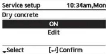 | |
| > Edit | |||
| Stages: 1Temperature: 25 °C | Heating temperature for drying the concrete.Select the desired stages: 1 ~ 10, range: 1 ~ 99 | 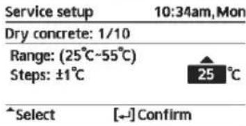 | |
| >ON | |||
| Confirm the setting temperatures of dry concrete for each stage. | 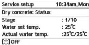 | ||
| 7.4 > Service contact | |||
| To set up to 2 contact names and numbers for the User. | Service engineer's name and contact number.Contact 1 / Contact 2 | 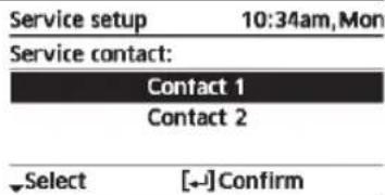 | |
| > Contact 1 / Contact 2 | |||
| Contact name or number.Name / phone icon | 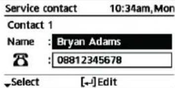 | ||
| Input name and numberContact name: alphabet a ~ z.Contact number: 1 ~ 9 | Contact-1 ■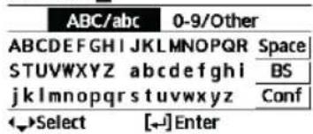 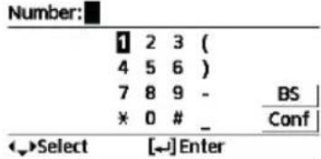 | ||
To ensure optimal performance of the system, cleaning has to be carried out at regular intervals. Consult an authorised dealer.
- Disconnect the power supply before cleaning.
- Do not use benzine, thinner or scouring powder.
- Use only soap (≈ pH7) or neutral household detergent.
- Do not use water hotter than 40^ .
Indoor unit
- Do not splash water directly. Wipe the unit gently with a soft dry cloth.
natural_image
Exterior view of a large industrial water heater unit with control panel and piping (no visible text or symbols)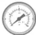
Water pressure gauge

- Do not press or hit the glass cover using hard and sharp objects. Failure to do so may cause damage to the unit.
- Ensure that the water pressure is between 0.05 and 0.3MPa (0.1 MPa = 1 bar).
- In case the water pressure is out of the above range, consult an authorised dealer.

Water filter
- Clean the water filter at least once a year. Failure to do so may cause the filter to clog up, which may lead to system breakdown. Consult an authorised dealer.
- Please also remove dust on the magnet.
Outdoor unit
- Do not obstruct the air inlet and outlet vents. Failure to do so may result in low performance or system breakdown. Remove any obstruction to assure the ventilation.
- When it snows, clean and remove snow around the outdoor unit to prevent the air inlet and outlet vents from being covered with snow.
For extended non-use
- The water inside the Tank Unit should be drained.
- Disconnect the power supply.
Non serviceable criteria
Disconnect the power supply
then please consult an authorised dealer under the following conditions:
- Abnormal noise during operation.
- Water/foreign particles have entered the Remote Controller.
• Water leaks from the indoor unit.
- Circuit breaker switches off frequently.
- Power cord becomes excessively warm.
MAINTENANCE
User
- In order to ensure optimal performance of the units, user may inspect and clear any obstruction on the air inlet and outlet vents of the outdoor unit.
- Users should not try to service or replace parts of the unit.
- Contact authorised dealer for scheduled inspection.
Dealer
- In order to ensure safety and optimal performance of the units, seasonal inspections on the units, functional check of RCCB/ELCB, water filter, field wiring and piping have to be carried out at regular intervals by authorised dealer.
Troubleshooting
The following symptoms do not indicate malfunction.
| Symptom Cause | |
| Water flowing sound during operation. | • Refrigerant flow inside the unit. |
| Operation is delayed a few minutes after restarting. | • The delay is a protection for the compressor. |
| Outdoor unit emits water/steam. | • Condensation or evaporation occurring in the pipes. |
| Steam comes out of the outdoor unit in the heating mode. | • It is caused by defrost operation in the heat exchanger. |
| Outdoor unit does not operate. | • It is caused by the protection control of the system when outdoor temperature is out of the operating range. |
| System operation switches off. | • It is caused by the protection control of the system. When the water inlet temperature is lower than 10 °C, the compressor stops and the backup heater power turns on. |
| System is hard to heat up. | • When the panel and the floor are heated simultaneously, warm water temperature may decrease, which may reduce the heating ability of the system.• When the outdoor air temperature is low, the system may need longer time to heat up.• Discharge outlet or intake inlet in the outdoor unit is blocked by some obstacle, such as a pile of snow.• When the preset water outlet temperature is low, the system may need longer time to heat up. |
| System does not heat up instantly. | • System will take some time to heat up the water if it starts to operate at cold water temperature. |
| Backup heater is automatically turned ON when it is disabled. | • It is caused by the protection control of the indoor unit heat exchanger. |
| Operation starts automatically when the timer is not set. | • Sterilization timer has been set. |
| Loud refrigerant noise continues for several minutes. | • It is caused by protection control during deice operation at outdoor ambient temperature lower than -10 °C. |
| *1.*2 COOL mode is unavailable. | • System has locked to operate in HEAT mode only. |
Check the following before calling for servicing.
| Symptom Check | |
| Operation in HEAT/ ^*1 . ^*2 COOL mode is not working efficiently. | Set the temperature correctly.Close the panel heater/cooler valve.Clear any obstruction in the air inlet and air outlet vents of the outdoor unit. |
| Noisy during operation. | Outdoor unit or indoor unit has been installed at an incline.Close the cover properly. |
| System does not work. • Circuit breaker | has tripped/activated. |
| Operation LED is not lit or nothing is displayed on the Remote Controller. | Power supply is working correctly, or a power failure has occurred. |
*1 The system is locked to operate without COOL mode. It can be unlocked only by authorised installers or our authorised service partners.
*2 Only displayed when COOL mode is unlocked (This means when COOL mode is available).
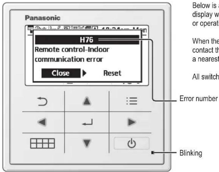
Below is a list of error codes that may appear on the display when there is some trouble with the system setting or operation.
When the display shows an error code as indicated below, contact the number registered in the Remote Controller or a nearest authorised installer.
All switches are disabled except and.
Error number
| Error No. | Error explanation |
| H12 | Capacity mismatch |
| H15 | Compressor sensor error |
| H20 | Pump error |
| H23 | Refrigerant sensor error |
| H27 | Service valve error |
| H28 | Solar sensor error |
| H31 | Pool sensor error |
| H36 | Buffer tank sensor error |
| H38 | Brand mismatch error |
| H42 | Low pressure protection |
| H43 | Zone 1 sensor error |
| H44 | Zone 2 sensor error |
| H62 | Water flow error |
| H63 | Low pressure sensor error |
| H64 | High pressure sensor error |
| H65 | Deice water circulation error |
| H67 | External thermistor 1 error |
| H68 | External thermistor 2 error |
| H70 | Back-up heater OLP error |
| H72 | Tank sensor error |
| H74 | PCB communication error |
| H75 | Low water temp protection |
| H76 | RC-Indoor communication error |
| H90 | Indoor-Outdoor communication error |
| H91 | Tank heater OLP error |
| H95 | Voltage connection error |
| H98 | High pressure protection |
| H99 | Indoor freeze prevention |
| Error No. | Error explanation |
| F12 | Pressure switch activated |
| F14 | Poor compressor rotation |
| F15 | Fan motor lock error |
| F16 | Current protection |
| F20 | Compressor overload protection |
| F22 | Transistor module overload protection |
| F23 | DC peak |
| F24 | Refrigerant cycle error |
| F25 | *1,*2 Cool / heat cycle error |
| F27 | Pressure switch error |
| F29 | Low discharge super heat |
| F30 | Water outlet sensor 2 error |
| F32 | Internal thermostat error |
| F36 | Outdoor ambient sensor error |
| F37 | Water inlet sensor error |
| F40 | Outdoor discharge sensor error |
| F41 | Power factor correction error |
| F42 | Outdoor heat exchanger sensor error |
| F43 | Outdoor defrost sensor error |
| F45 | Water outlet sensor error |
| F46 | Current transformer disconnection |
| F48 | Evaporator outlet sensor error |
| F49 | Bypass outlet sensor error |
| F95 | *1,*2 Cooling high pressure error |
* Some error code may not be applicable to your model. Consult authorised dealer for clarification.
*1 The system is locked to operate without COOL mode. It can be unlocked only by authorised installers or our authorised service partners.
*2 Only displayed when COOL mode is unlocked (This means when COOL mode is available).
Information when connect to Network Adaptor (Optional Accessories Part)

WARNING
Before use, check the safety around the Air-to-Water system. Confirm human and living objects at surrounding before operation.
Incorrect operation due to failure to follow instructions may cause harm and damage.

Confirm the below before operation (inside premises)
- Timer setting condition. Unpredictable on/off operation may cause serious injury or damage to human and living objects.
Confirm the below before and during operation (outside from premises)
- If is known someone in the premises, notify the person from outside of new operation setting prior executing. This is to avoid sudden shock to the person and any serious health breakdown duly from operation changed.
- Please do not use this appliance when infant, physical disability person or elderly who unable to operate the appliance by themselves in the premises.
- Check the setting and operation status frequently.
- Stop the operation when error code is displayed and consult an authorised dealer or specialist.
Please confirm before use
- The system may not usable when communication condition is bad. Please check “Operation Status” from the application display after operation. The following condition may happen in the remote operation.
- Cannot operate, operation time is not reflected.
- Air-to-Water operation is not reflected when operation is set outside of premises.
- It is recommended to lock screen the smart phone device to prevent miss-operation.
- Do not use other remote control, communication and operation device not specified by an authorised dealer or specialist.
- Use under the agreement of "Terms of Service" and "Handling of Personal Information" of Panasonic Smart Application.
- For extended non-use of Panasonic Smart Application, disconnect the network adaptor from the device.
Information for Users on Collection and Disposal of Old Equipment
This symbol on the products, packaging, and/or accompanying documents means that used electrical and electronic products must not be mixed with general household waste.
For proper treatment, recovery and recycling of old products, please take them to applicable collection points in accordance with your national legislation.
By disposing of these products correctly, you will help to save valuable resources and prevent any potential negative effects on human health and the environment which could otherwise arise from inappropriate waste handling.
For more information about collection and recycling of old products, please contact your local municipality, your waste disposal service or the point of sale where you purchased the items.
Penalties may be applicable for incorrect disposal of this waste, in accordance with national legislation.
For business users in the European Union
If you wish to discard electrical and electronic equipment, please contact your dealer or supplier for further information.
[Information on Disposal in other Countries outside the European Union]
These symbols are only valid in the European Union. If you wish to discard these items, please contact your local authorities or dealer and ask for the correct method of disposal.
![PANASONIC WHSDC0709J3E5 - [Information on Disposal in other Countries outside the European Union] - 1](/content/2026/03/461017/images/83a616005f17ac4cab4a2d9f1ae91f49594cb46b37aa3c04d561a120439366aa.jpg) WARNING WARNING | This symbol shows that this equipment uses a flammable refrigerant. If the refrigerant is leaked, together with an external ignition source, there is a possibility of ignition. | ![PANASONIC WHSDC0709J3E5 - [Information on Disposal in other Countries outside the European Union] - 2](/content/2026/03/461017/images/d58a879ad98077cf6a8695adde1c5dc47d61fc1273f1056306a357743b83eec8.jpg) | This symbol shows that the Operation Instructions should be read carefully. |
![PANASONIC WHSDC0709J3E5 - [Information on Disposal in other Countries outside the European Union] - 3](/content/2026/03/461017/images/4dce29729545a6c48bfb3782150d8a07573d11332fb6486c049cd834691cc2ee.jpg) | This symbol shows that a service personnel should be handling this equipment with reference to the Installation Instructions. | ![PANASONIC WHSDC0709J3E5 - [Information on Disposal in other Countries outside the European Union] - 4](/content/2026/03/461017/images/cc5ad763fbac9e4e9744f6adff17313cabe5f62a252dce35367c06315005d232.jpg) | This symbol shows that there is information included in the Operation Instructions and/or Installation Instructions. |
natural_image
Hand pointing at a grid with directional arrows (no text or symbols)![PANASONIC WHSDC0709J3E5 - [Information on Disposal in other Countries outside the European Union] - 5](/content/2026/03/461017/images/3d28c3d1b449a789ae6838cefb326015b3beaa917719ef563b7b45b8a9a91eea.jpg)
Ingen pen
![PANASONIC WHSDC0709J3E5 - [Information on Disposal in other Countries outside the European Union] - 6](/content/2026/03/461017/images/5029e8df95a69573c443a5d0a48927dd896bbcebb6d3c53f53957f88daf93fe3.jpg)
natural_image
Hand holding a pen writing on a grid, no text or symbols presentnatural_image
Exterior view of a large industrial pressure vessel with control panel and piping (no visible text or symbols)![PANASONIC WHSDC0709J3E5 - [Information on Disposal in other Countries outside the European Union] - 7](/content/2026/03/461017/images/4f8ac0a765e1c770f4f895de17e31f1e44b70652df17dbdf7136693bd4354f2a.jpg)
Vandtrykmåler

5.9 Res. band. condens.
5.10 Sensor exterior alternativo
natural_image
Hand pointing at a grid with directional arrows (no text or symbols)
No use bolígrafos

natural_image
Hand holding a pen writing on a grid, no text or symbols presentPantalla
natural_image
Exterior view of a cylindrical industrial vessel with control panel and piping (no visible text or symbols)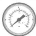
Manómetro

natural_image
Hand pointing at a grid with directional arrows (no text or symbols)
Senza penna

natural_image
Hand holding a pen writing on a grid, no text or symbols present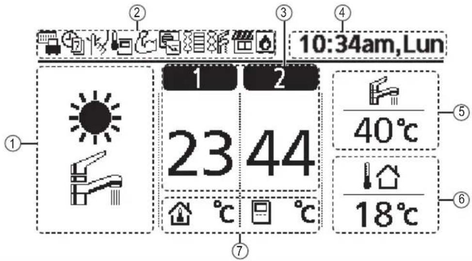
Display
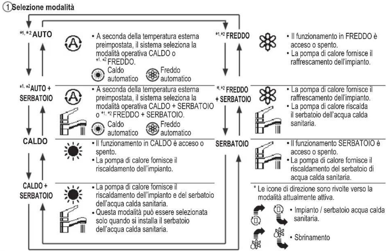
![Lingua 12:00am,Lur ENGLISH FRANÇAIS DEUTSCH ITALIANO Selez. [←] Conf.](/content/2026/03/461017/images/026aab361156c8382eae2c34008654e3e6c3e380c5f89390fef42956d0bb9e64.jpg)
![Formato orologio 12:00am,Lur 24 H am/pm ^Selez. [←] Conf.](/content/2026/03/461017/images/5a4d80e9e8e9591b1358b11c15043c3478c915c3d6d226acc06b4b7831384b01.jpg)
![Data e Ora 12:00am,Lur Anno/Mes/Gio Ora:Min 2015/01/01 12:00 am →Selez. [←]Conf.](/content/2026/03/461017/images/0740621a4fe0d1527a4f03e1c8960fef5da93c5924bfc4ce2be62382e4d52b4b.jpg)
| 10:00am,Mer |
| [+] Avvio |
natural_image
Exterior view of a large industrial pressure vessel with control panel and piping (no visible text or symbols)7.4 Service contactpers.
natural_image
Hand pointing at a grid with directional arrows (no text or symbols)
Gebruik geen pen

natural_image
Hand holding a pen writing on a grid, no text or symbols present
Forceren warmtapwater

Przyciski kursora
Wybór pozycji.
natural_image
Hand pointing at a grid with directional arrows (no text or symbols)natural_image
Hand holding a pen writing on a grid, no text or symbols presentnatural_image
Exterior view of a cylindrical industrial or laboratory vessel with control panel and piping (no visible text or symbols)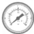
Manometr wody

natural_image
Hand pointing at a grid with directional arrows (no text or symbols)
Χωρίς στυλό

natural_image
Hand holding a pen writing on a grid, no text or symbols presentKurzorová tlačítka
Výběr položky.
natural_image
Hand pointing at a grid with directional arrows (no text or symbols)
Ne perem
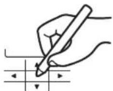
natural_image
Hand holding a pen writing on a grid, no text or symbols presentnatural_image
Exterior view of a cylindrical industrial vessel with control panel and piping (no text or symbols visible)
Tlakoměr vody

1.2 Programme vacances
1.3 Programme Silence
7.4 Contact maintenance
Instructions De Nettoyage ....339
natural_image
Hand pointing at a grid with directional arrows (no text or symbols)
Sans stylo

natural_image
Hand holding a pen writing on a grid with arrows indicating direction (no text or symbols present)
natural_image
Hand pointing at a grid with directional arrows (no text or symbols)
Kein Stift

natural_image
Hand holding a pen writing on a grid, no text or symbols present![Sprache 12:00am,Mc ENGLISH FRANÇAIS DEUTSCH ITALIANO Wählen [←]Bestät.](/content/2026/03/461017/images/1ff84522f5444c36a94d81fb8f2fbf3d1b11b3a83ea6079e4cdbc5e304d2f94e.jpg)
![Zeitformat 12:00am,Mo 24 h AM / PM Wählen [←]Bestät.](/content/2026/03/461017/images/cde0110ad8b374bcba20443e229be1db882b9c7fb1ff5bbe16d42fb0c2a93abe.jpg)
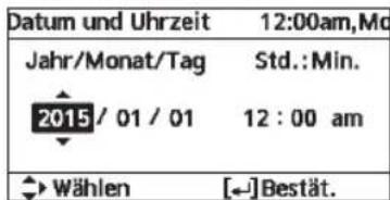
natural_image
Exterior view of a large industrial water heater unit with control panel and piping (no visible text or symbols)natural_image
Hand pointing at a grid with directional arrows (no text or symbols)
Kalem yok
