
WMR86NSX - Weather Station OREGON SCIENTIFIC - Free user manual and instructions
Find the device manual for free WMR86NSX OREGON SCIENTIFIC in PDF.
| Product type | Professional weather station |
| Brand | Oregon Scientific |
| Model | WMR86NSX |
| Base station dimensions | 94 x 51 x 182.5 mm (L x W x H) |
| Base station weight | 241 g (without batteries) |
| Base station power supply | 3 AA 1.5 V batteries or 5 V DC power adapter |
| Included sensors | Anemometer/wind vane, rain gauge, outdoor temperature/humidity sensor |
| Max number of remote sensors | 3 |
| Wireless range | 100 m (328 ft) in open field |
| Transmission frequency | 433 MHz |
| Display | Color LCD with backlight |
| Main functions | Weather forecast (12-24 h), indoor/outdoor temperature, humidity, wind speed and direction, rainfall, UV index, barometric pressure, radio-controlled clock, moon phase |
| Anemometer power supply | 2 AA 1.5 V batteries |
| Rain gauge power supply | 2 AA 1.5 V batteries |
| Outdoor TH sensor power supply | 2 AAA 1.5 V batteries |
| Maintenance and cleaning | Do not immerse; clean with a soft cloth; do not use abrasive products |
| Safety | Do not expose to excessive force, dust or moisture; do not block ventilation openings |
| Spare parts and repairability | Additional sensors and accessories (solar panel) are available from retailers |
| General information | Compliant with Directive 2014/53/EU; recycling according to WEEE; manual downloadable from Oregon Scientific website |
Frequently Asked Questions - WMR86NSX OREGON SCIENTIFIC
User questions about WMR86NSX OREGON SCIENTIFIC
0 question about this device. Answer the ones you know or ask your own.
Ask a new question about this device
Download the instructions for your Weather Station in PDF format for free! Find your manual WMR86NSX - OREGON SCIENTIFIC and take your electronic device back in hand. On this page are published all the documents necessary for the use of your device. WMR86NSX by OREGON SCIENTIFIC.
USER MANUAL WMR86NSX OREGON SCIENTIFIC
Pro Colour Weather Station Model: WMR86NS / WMR86NSA
USER MANUAL
CONTENTS
Introduction. 1
Packaging Contents 1
Base Station 1
Wind Sensor. 1
Temperature & Humidity Sensor 1
Rain Gauge 2
Accessories - Sensors 2
Overview 2
Front View 2
Back View 2
LCD Display 2
Wind Sensor 3
Rain Gauge 4
Outdoor Temperature / Humidity Sensor. 4
Getting Started. 4
Set Up Remote Wind Sensor 4
Set Up Remote Temperature / Humidity Sensor..4
- Set Up Rain Gauge 43
Set Up Base Station 5
Connect AC Adapter 5
Verify Connection 5
Wind Sensor. 5
Temperature / Humidity Sensor 5
Rain Gauge 5
Mounting / Placing Of Sensors 6
Wind Sensor. 6
Temperature / Humidity Sensor 6
Rain Gauge 6
Clock Reception 6
Clock/Calendar 7
Moon Phase 7
Auto Scanning Function 7
Weather Forecast 7
Temperature And Humidity 8
Temperature And Humidity Trend. 8
Wind Chill / Direction / Speed 8
Uvi / Barometer / Rainfall 8
UV Index 9
Barometer 9
Rainfall 9
Backlight 9
Reset. 9
Specifications 9
Precautions 10
About Oregon Scientific 11
EU Declaration Of Conformity 11
FCC statement 11
DISPOSAL INFORMATION FOR USERS 11
INTRODUCTION
Thank you for selecting the Oregon Scientific™ Weather Station (WMR86NS / WMR86NSA).
The base station is compatible with other sensors. To purchase additional sensors, please contact your local retailer.

Sensors with this logo 3.0 are compatible with this unit.
NOTE Please keep this manual handy as you use your new product. It contains practical step-by-step instructions, as well as technical specifications and warnings you should know about.
PACKAGING CONTENTS
BASE STATION
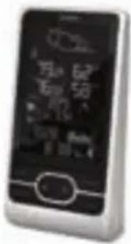
1 x Base Station
3 x AA UM-3 1.5V batteries
1x Power Adapter
WIND SENSOR
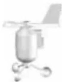
1 x Wind Sensor (1 x Wind Vane Above and 1 x Anemometer Below)

2 x AA UM-3 1.5V batteries
1 x sensor connector
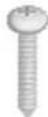
4 x Screws (Type A)
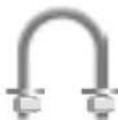
1 x Round U- bolt
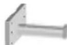
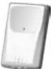
TEMPERATURE & HUMIDITY SENSOR
1 x Temperature / Humidity Sensor
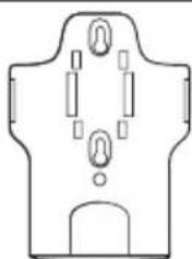
1xwallmount bracket
1 x Table stand

2x AAA UM-4 1.5V battery
RAIN GAUGE
1 x Rain Collector
4xScrews (Type B)
2xAAUM-3 1.5V batteries

6 x Washers
ACCESSORIES - SENSORS
This product can work with up to 3 sensors at any one time to capture outdoor temperature, relative humidity or UV readings in various locations.
Optional wireless remote sensors such as those listed below can be purchased separately. For more information, please contact your local retailer.*
- Solar Panel STC800 connectable to Wind Sensor and Temperature / humidity sensor
Thermo-hygro THGR800 (3-Ch)
Thermo-hygro THGR810 (10-Ch)
UV UVN800 - Pool sensor THWR800
- Features and accessories will not be available in all countries.
OVERVIEW
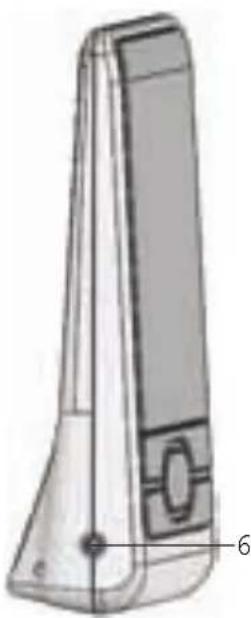
FRONT VIEW
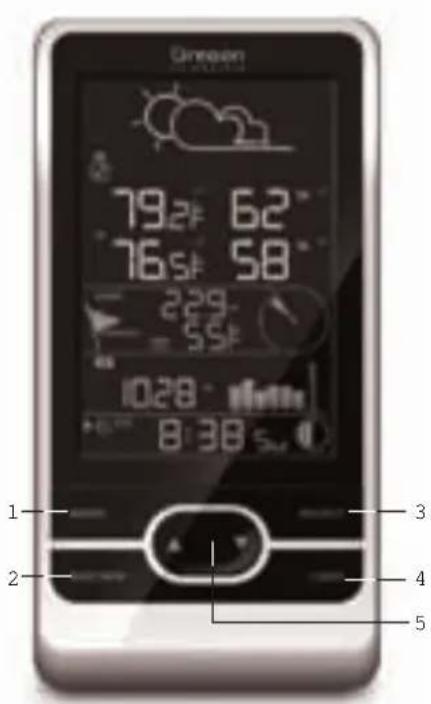
- MODE: Switch between the different display modes / settings; set clock; set altitude; activate autoscan
- MAX/MIN: Read the max / min memory readings; clear readings
-
SELECT: Switch between the different areas
-
LIGHT: Activate backlight
- Increase/decrease values of the selected setting; toggle between outdoor channels
BACK VIEW
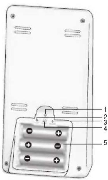
- RESET: Returns unit to default settings
- UNIT: Select unit of measurement
- SEARCH: Searches for sensors or for the radio-controlled clock signal
- EU / UK switch: Select the nearest radio signal (WMR86NS only)
- Battery compartment
- AC power adapter jack
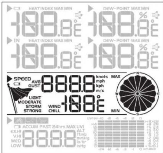
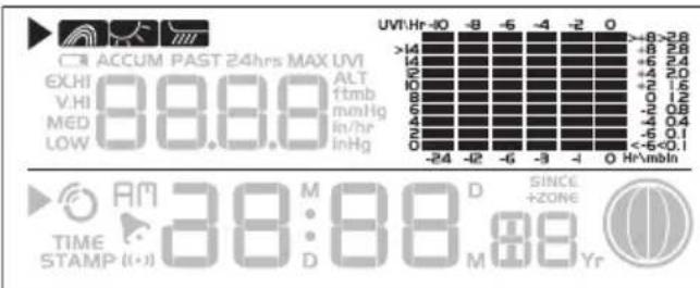
LCD DISPLAY
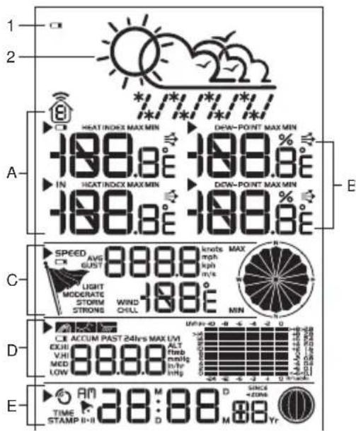
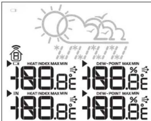
- Main unit battery low
- Weather forecast
A. Temperature/Heat Index Area
B. Humidity / Dew Point Area
C. Wind Speed / Wind Direction / Wind Chill Area
D. UVI / Barometer / Rainfall Area
E. Clock / Calendar / Moon Phase Area
A Temperature Area
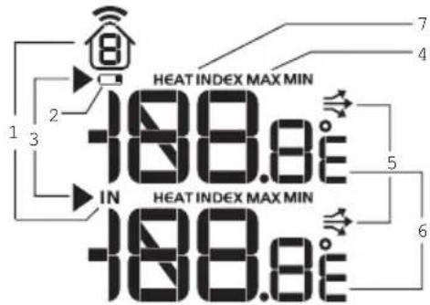
- Indoor In Outdoor humidity is displayed

nnel temperature and
- Outdoor sensor battery is low
- Selected area icon
- MAX/MIN temperature is displayed
- Temperature trend
- Temperature reading (^ / ^)
- Heat Index
B Humidity/Dew Point Area
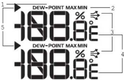
- Dew point level - Temperature is displayed
- MAX / MIN humidity / dew point level is displayed
- Humidity trend
- Humidity reading
- Selected area icon
C Wind Speed / Wind Direction / Wind Chill Area
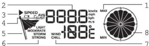
- MAX wind speed memory display
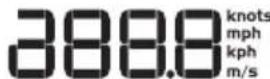
- Wind speed reading (m/s, knots, kph or mph)
- Outdoor wind sensor low battery display
- Wind speed indicator (AVG/GUST)
- Wind speed level indicator
- Wind speed level description
-
Minimum wind chill display
-
Wind direction indicator
D UVI / Barometer / Rainfall Area
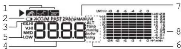
- Barometer/UVI/rainfall reading indicator
- Outdoor UVI/rain sensor low battery display
- ACCUM/PAST 24hrs - displays accumulative/past 24 hours rainfall
4.Barometer/UVI/rainfall readings - UVI level indicator
- Barometric pressure/UVI/rainfall units displayed
- MAX barometer/UVI/rainfall display
- Barometric pressure/UVI/rainfall historical bar chart display
E Clock / Calendar / Moon Phase Area
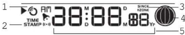
- Check signal reception indicator
- Timestamp is displayed
- Time zone offset
- Moon phase
- Time / date / calendar
WIND SENSOR
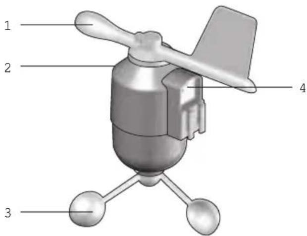
- Wind direction
- Wind vane casing
- Anemometer
- Solar power socket
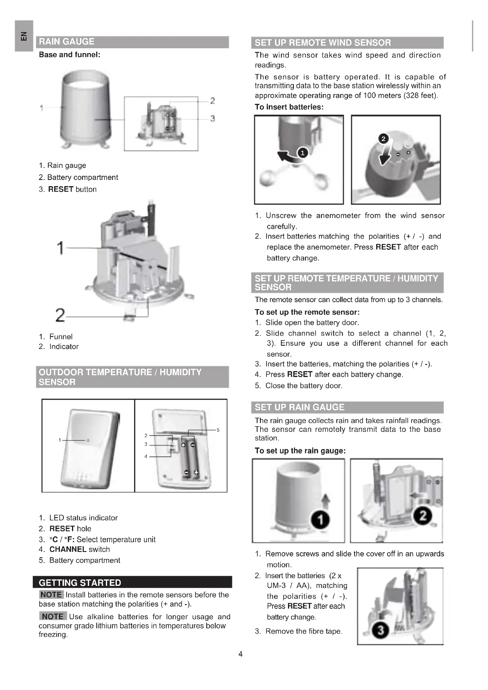
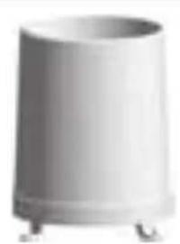
RAIN GAUGE
Base and funnel:
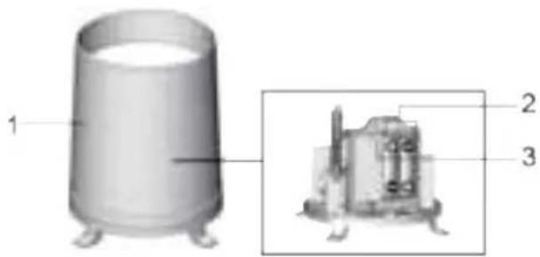
- Rain gauge
- Battery compartment
- RESET button
- Funnel
- Indicator
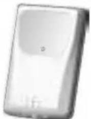
OUTDOOR TEMPERATURE/HUMIDITY SENSOR
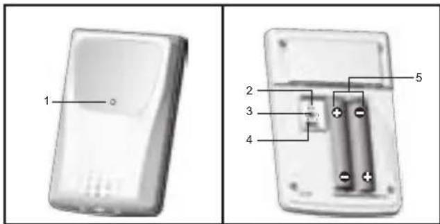
- LED status indicator
- RESET hole
- ^ C / ^ F : Select temperature unit
- CHANNEL switch
- Battery compartment
GETTING STARTED
NOTE Install batteries in the remote sensors before the base station matching the polarities (+ and -).
NOTE Use alkaline batteries for longer usage and consumer grade lithium batteries in temperatures below freezing.
SET UP REMOTE WIND SENSOR
The wind sensor takes wind speed and direction readings.
The sensor is battery operated. It is capable of transmitting data to the base station wirelessly within an approximate operating range of 100 meters (328 feet).
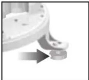
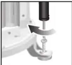
To insert batteries:
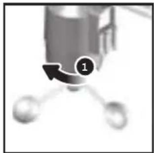
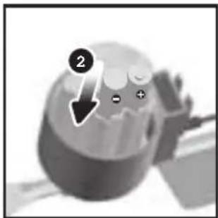
- Unscrew the anemometer from the wind sensor carefully.
- Insert batteries matching the polarities (+ / -) and replace the anemometer. Press RESET after each battery change.
SET UP REMOTE TEMPERATURE / HUMIDITY SENSOR
The remote sensor can collect data from up to 3 channels.
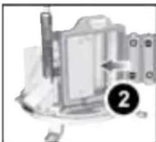
To set up the remote sensor:
- Slide open the battery door.
- Slide channel switch to select a channel (1, 2, 3). Ensure you use a different channel for each sensor.
- Insert the batteries, matching the polarities (+ / -) .
- Press RESET after each battery change.
- Close the battery door.
SET UP RAIN GAUGE
The rain gauge collects rain and takes rainfall readings. The sensor can remotely transmit data to the base station.
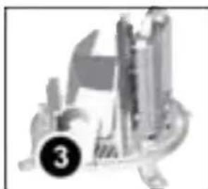
To set up the rain gauge:
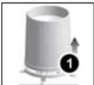
- Remove screws and slide the cover off in an upwards motion.
- Insert the batteries (2 x UM-3 / AA), matching the polarities (+/ -). Press RESET after each battery change.
- Remove the fibre tape.
SETUPBASESTATION
NOTE Install batteries in the remote sensors before the base station matching the polarities (+ and -).
- Slide open the battery door.
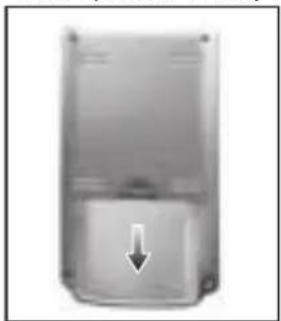
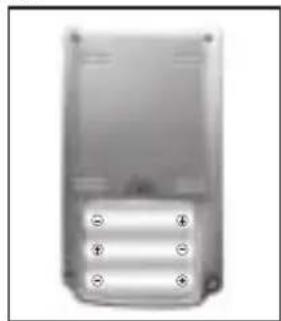
- Insert the batteries, matching the polarities (+ / -) .
- Press RESET after each battery change.
- Close the battery door.
NOTE Do not use rechargeable batteries. It is recommended that you use alkaline batteries with this product for longer performance.
NOTE Batteries should not be exposed to excessive heat such as sunshine or fire.
The battery icon indicator may appear in the following areas:
| AREA MEANING | |
| Weather Forecast Area | Battery in the base station is low. |
| Temperature or Humidity Area | The displayed channel indicates the outdoor sensor for which battery is low. |
| Wind Speed / Wind Direction / Wind Chil Area | Battery in the wind sensor is low. |
| UVI / Barometer / Rainfall Area | Battery in the UV / Rain sensor is low. |
CONNECT AC ADAPTER
Connect the supplied power adapter to the power jack, then plug into a standard AC outlet.
NOTE
- The batteries are only for back-up use. Always connect the unit to the power grid source via AC/DC adapter.
- Make sure the adapter is not obstructed and is easily accessible to the unit.
- The base station and adapter should not be exposed to wet conditions. No objects filled with liquid, such as vases, should be placed on the base station and adapter.
- To completely disconnect from power, unplug adapter from the mains.
VERIFY CONNECTION
Before proceeding to install sensors outside, please verify communication to the base station.
WIND SENSOR
Press SELECT until the selected area icon is in the middle display area.
- Wind speed: Gently rotate the wind vane and confirm a numerical reading on the base station, e.g., 1789
- Wind direction indicator. Move the direction of the wind indication and verify the icon moves in the same direction.
TEMPERATURE/HUMIDITY SENSOR
- Press SELECT until the selected area icon is in the upper display area.
- Press to select channel 1 and verify a numerical reading.
RAIN GAUGE
- Press SELECT until the selected area icon is in the lower display area.
- Press MODE until splayed.
- Tilt the tipping funnel on the rain gauge several times and verify a numerical reading on the base station.
TIP If no reading is displayed for a sensor, press and hold SEARCH button on the base station to initiate a wireless sensor search.
MOUNTING / PLACING OF SENSORS
WIND SENSOR
NOTE The sensor should be positioned in an open area away from trees or other obstructions.
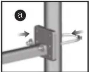
Secure the sensor connector in the desired location:
a. Align the back of the sensor connector to an existing pole. Secure in place by inserting the ends of the U-bolt into the holes on the sensor connector and securing it with washers and bolts.
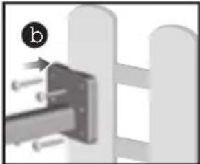
OR
b. Insert 4 type A screws into the holes of the sensor connector. Screw firmly into place, i.e., fence.
Slide wind vane onto the smaller end of the sensor connector.
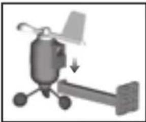
IMPORTANT Ensure that the wind sensor is pointing North to enable it to record accurate readings.
TEMPERATURE/HUMIDITY SENSOR
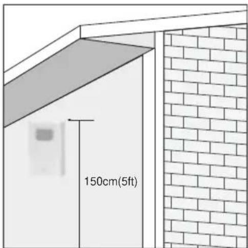
TIP Ideal placements for the sensor would be in any location on the exterior of the home at a height of not more than 1.5m (5 ft) and which can shield it from direct sunlight or wet conditions for an accurate reading.
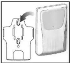
Secure the sensor in the desired location using the wall mount bracket or table stand.
RAIN GAUGE
The base station and rain gauge should be positioned within an effective range: about 100 meters (328 feet) in an open area.
The rain gauge should be mounted horizontally about 1 meter (3 feet) from the ground in an open area away from trees or other obstructions to allow rain to fall naturally for an accurate reading.
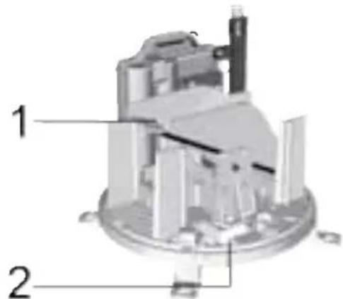
To ensure a level plane:
Put a few drops of water on the cross at the base of the funnel to check the horizontal level.
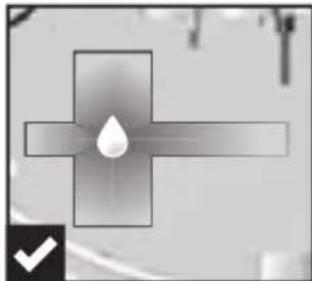
Water will pool to the center of the cross when the rain gauge is level.
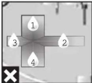
If water remains on 1-4, the gauge is not horizontal. If necessary, adjust the level using the screw.
NOTE For best results, ensure the base is horizontal to allow maximum drainage of any collected rain.
TIP Press RESET button on base station to erase all testing data.
CLOCK RECEPTION
This product is designed to synchronize its calendar clock automatically once it is brought within range of a radio signal:
WMR86NS:
EU: DCF-77 signal: within 1500 km (932 miles) of Frankfurt, Germany.
UK: MSF-60 signal: within 1500km (932 miles) of Anthorn, England.
WMR86NSA:
- WWVB-60 signal: within 3200km (2000 miles) of Fort Collins Colorado.
WMR86NS only - slide the EU / UK switch to the appropriate setting based on your location. Press RESET whenever you change the selected setting.
The reception icon will blink when it is searching for a signal. If the radio signal is weak it can take up to 24 hours to get a valid signal reception.

indicates the status of the clock reception signal.
| ICON MEANING | |
| Time is synchronized. Receiving signal is strong | |
| Time is not synchronized. Receiving signal is weak | |
To enable (and force a signal search) / disable the clock radio reception (clock synchronization):
-
Press SELECT to navigate to the Clock / Calendar / Moon Phase Area. will show next to the Area.
-
Press and hold SEARCH.

appears when it is enabled.
NOTE For best reception, the base station should be placed on a flat, non-metallic surface near a window in an upper floor of your home. The antenna should be placed away from electrical appliances and not be moved around when searching for a signal.
CLOCK /CALENDAR
To manually set the clock:
(You only need to set the clock and calendar if you have disabled the clock radio reception).
-
Press SELECT to navigate to the Clock Area. will show next to the Area.
-
Press and hold MODE to change the clock setting. The setting will blink.
-
Press / to increase/decrease the setting value.
-
Press MODE to confirm.
-
Repeat steps 3 to 4 to set the time zone offset hour (+ / -23 hours), 12/24 hour format, hour, minute, year, date / month format, month, date and weekday language.
NOTE If you enter +1 in the time zone setting, this will give you your regional time plus 1 hour.
If you are in the US (WMR86NSA only) set the clock to:
Pacific time Mountain time
Central time Eastern time
NOTE The weekday is available in English (E), German (D), French (F), Italian (I), Spanish (S) or Russian (R).
To change the clock display:
- Press SELECT to navigate to the Clock Area. will show next to the Area.
- Press MODE to toggle between:
- Clock with Seconds
- Clock with Weekday
Calendar
MOON PHASE
The Calendar must be set for this feature to work (see Clock/Calendar section).
| New Moon Full Moon | |||
| Waxing Crescent | Waning Gibbous | ||
| First quarter | Third quarter | ||
| Waxing Gibbous | Waning Crescent |
AUTO SCANNING FUNCTION
To activate the outdoor temperature and humidity auto-scan function:
- Press SELECT to navigate to the Temperature or Humidity Area. will show next to the Area.
- Press and hold MODE to activate auto-scan. The temperature and humidity display will scroll from indoor to ch1 through to ch3.
- Press any key except the LIGHT to stop the auto-scan.
NOTE Channel 1 is used for the outdoor temperature and humidity sensor. Additional temperature and humidity sensors can use other channels.
WEATHER FORECAST
The weather display in the top part of the screen shows the current weather and the weather forecast for the next 12-24 hours within a 30 - 50km (19-31 mile) radius.
Weather Forecast Area
| ICON | DESCRIPTION |
| Sunny | |
| Partly cloudy | |
| Cloudy | |
| Rainy | |
| Snowy |
TEMPERATURE AND HUMIDITY
The weather station displays indoor and outdoor readings for:
- Temperature / relative humidity (current / maximum / minimum)
- Trend line
- Dew point level/Heat index
The weather station can connect up to 3 remote sensors.
NOTE Channel 1 is dedicated for outdoor temperature and humidity.
shows which remote sensor's data you are viewing.
IN appears when indoor data is displayed.
The timestamp records the date and time when storing the temperature and humidity readings in memory.
To select the temperature measurement unit:
Press UNIT to select ^ C / ^ F
NOTE The unit of all temperature related displays will be changed simultaneously.
To view temperature (Current / Min / Max temperature) readings:
- Press SELECT to navigate to the Temperature Area.
will show next to the Area. - Press to select the channel.
- Press MODE repeatedly to toggle between the temperature/heat index displays.
- Press MAX / MIN to toggle between current / MAX / MIN displays.
To view humidity (Humidity, Dew point) readings:
- Press SELECT to navigate to the Humidity Area. will show next to the Area.
- Press to select the channel.
- Press MODE repeatedly to toggle between the humidity / dew point displays.
- Press MAX / MIN to toggle between current / MAX / MIN displays.
The timestamp is displayed accordingly in the Clock Area.
To clear the memories and timestamp for the temperature, humidity and dew point readings:
In the Temperature or Humidity Area, press and hold MAX / MIN to clear the readings.
NOTE The heat index provides an indication on how hot it feels based on air temperature and relative humidity.
NOTE The dew point advises at what temperature condensation will form.
TEMPERATURE AND HUMIDITY TREND
The trend lines are shown next to the temperature and humidity readings. The trend is shown as follows:
| RISING STE | ADY FALLING | |
| → | → | → |
The base station provides wind speed and wind direction information.
To read the wind direction find the compass point the is pointing to.

The timestamp records the date and time when storing the wind speed readings.
To select the wind speed unit:
Press UNIT to switch between:
- Metres per second (m / s)
- Kilometers per hour (kph)
- Miles per hour (mph)
- Knots (knots)
The wind level is shown by a series of icons:
| ICON | LEVEL | DESCRIPTION |
| N/A <2 mph (<4km/h) | ||
| Light 2-8 mph (3~13 km/h) | ||
| Moderate 9-25 mph (~14-41 km/h) | ||
| Strong 26-54 mph (~42-87 km/h) | ||
| Storm >55 mph (>88 km/h) | ||
To view the maximum wind speed and minimum wind chill readings:
- Press SELECT to navigate to the Wind Speed / Wind Direction / Wind Chill Area. will show next to the Area.
- Press MAX / MIN to toggle between current / MAX wind speed and current / MIN wind chill displays.
The timestamp is displayed accordingly in the Clock Area.
To clear minimum wind chill reading / maximum wind speed reading:
- Press SELECT to navigate to the Wind Speed / Wind Direction / Wind Chill Area. will show next to the Area.
- Press MAX / MIN repeatedly until minimum wind chill reading or maximum wind speed reading is displayed.
- Press and hold MAX / MIN to clear the readings.
NOTE The wind chill factor is based on the combined effects of temperature and wind speed. Displayed wind chill is calculated solely from Channel 1 sensors.
UVI / BAROMETER / RAINFALL
The weather station works with one UV sensor and one rain gauge. The station is capable of storing and
displaying the hourly history data for the last 10 hours of UV index, and 24 hours of rainfall and barometric pressure readings.
UVIBAROMETERRAINFALL
| UV/1Hr 40 45 4 2 0 | →8 +8 +6 +4 +2 -2 -4 -6 -6 -6 -6 -6 -6 -6 -6 -6 -6 -6 -6 -6 -6 -6 -6 -6 -6 -6 -6 -6 -6 -6 -6 -6 -6 -6 -6 -6 -6 -6 -6 -6 -6 |
The bar chart display shows the current and historical data for the UV index, barometric pressure and rainfall readings.
NOTE The number shown in the horizontal axis (Hr) indicates how long ago each measurement was taken (e.g. 3 hours ago, 6 hours ago, etc.). The bar represents the measurement taken for that specific 1 hour period. E.g., if it is 10:30 pm now, the bar plotted directly above -1 shows the reading recorded from 9 to 10 pm and -6 shows the reading recorded earlier in the evening, between 4pm-5pm.
To view the UV / Barometer / Rainfall readings:
- Press SELECT to navigate to the UV / Barometer / Rainfall Area. will show next to the Area.
- Press MODE to toggle between UVI / Barometer / Rainfall readings. The corresponding icon will appear:
| BAROMETER UVI RAINFALL | ||
To select the measurement unit for the barometer or rainfall readings:
In the UV / Barometer / Rainfall Area, press UNIT to switch between:
- Barometer: Millimeters of mercury (mmHg), inches of mercury (inHg), millibars per hectopascal (mb).
- Rainfall: Millimeters (mm), inches (in), recorded for that hour.
NOTE As the purpose of the bar graph is only to provide a quick comparison between the records of the past 24 hours, the vertical axis cannot convert from inches to mm. Therefore, changing the measurement unit will have no effect on the bar graph display.
UV INDEX
The UV index levels are as follows:
| UV INDEX DANGER LEVEL ICON | ||
| 0-2 Low | LOW | |
| 3-5 Moderate | MED | |
| 8-10 Very high | V.HI | |
| 11 and above | Extremely high | EX.HI |
To view the maximum UV reading:
- Press SELECT to navigate to the UVI / Barometer / Rainfall Area. will show next to the Area.
-
Press MODE repeatedly to select UV display.
-
Press MAX / MIN to toggle between current / MAX UV index display.
The timestamp is displayed accordingly in the Clock Area.
To clear maximum UV reading:
- Press SELECT to navigate to the UVI / Barometer / Rainfall Area. will show next to the Area.
- Press MODE repeatedly to select UV display.
- Press and hold MAX / MIN to clear the readings.
BAROMETER
To set the altitude level compensation for the Barometer readings:
- Press SELECT to navigate to the UVI / Barometer / Rainfall Area. will show next to the Area.
- Press MODE repeatedly to select Barometric display.
- Press and hold MODE to enter the altitude setting.
- Press / to increase/decrease the setting value.
- Press MODE to confirm the setting.
RAINFALL
To view the recorded rainfall of the current hour or last 24 hours:
- Press SELECT to navigate to the UVI / Barometer / Rainfall Area. will show next to the Area.
- Press MODE repeatedly to select Rainfall display.
- Press MAX / MIN repeatedly to toggle between current, past 24 hour rainfall or accumulated rainfall readings.
BACKLIGHT
Press LIGHT to activate the backlight for 5 seconds.
RESET
Press RESET to return to the default settings.
SPECIFICATIONS
BASE STATION
| Dimensions | 94 x 51 x 182.5 mm |
| (L x W x H) | (3.7 x 2.0 x 7.2 inches) |
| Weight | 241 g (8.5 oz) without battery |
| Battery | 3 x UM-3 (AA) 1.5V |
| AC/DC Adapter | Input: 120 V, 60 Hz 50 mA Output: DC 5V, 100 mA |
INDOOR BAROMETER
| Barometer unit | mb, inHg and mmHg |
| Measuring range | 700 - 1050mb/hPa |
| Accuracy | +/- 10 mb/hPa |
| Altitude setting | Sea level User setting for compensation |
| Weather display | Sunny, Partly Cloudy, Cloudy, Rainy and Snowy |
INDOOR TEMPERATURE
Temp. unit ^ C / ^ F
Displayed range -5^ 50^ ( 23^ 122^ )
Operating range 0^ to 50^ (32^ to 122^)
Accuracy 0^ - 40^: +/-1°C (+/-2.0°F)
40^ - 50^: + / - 2^(+ / - 4.0^)
Memory Current, Min and Max temp.
Dew Point w/ Min and Max
INDOOR RELATIVE HUMIDITY
Displayed range 2% to 98%
Operating range 25% to 90%
Accuracy 25% -40% ..+/-7%
40% - 80%: +/ - 5%
80% - 90%: +/ - 7%
Memory Current, Min and Max
RADIO-CONTROLLED / ATOMIC CLOCK
Synchronization Auto or disabled
Clock display HH:MM:SS
Hour format 12hr AM/PM or 24hr
Calendar DD/MM or MM/DD
Weekday in 5 (E, D, F, I, S, R)
languages
REMOTE WIND SENSOR UNIT
Dimensions
178× 76× 214mm
(7 × 3 × 8.4 inches)
Weight 100 g (0.22 lbs) without battery
Wind speed unit m/s, kph, mph, knots
Speed accuracy 2m / s 10m / s(+ / - 3m / s)
10 m/s ~ 56 m/s (+/- 10%)
Direction accuracy
16 positions
Transmission of wind speed signal
Approx. every 56 seconds
Memory
Max wind speed
Battery 2 × UM-3 (AA) 1.5V batteries
OUTDOOR TEMPERATURE / HUMIDITY UNIT
Dimensions
92 × 60 × 20 ~mm
62 g (2.22oz) without battery
Humidity range
25% to 95%
Humidity accuracy
25% - 40%: +/ - 7%
40% - 80%: +/- 5%
80% - 90%: +/- 7%
Temp. unit
^ C / F
Temperature
-30°C to 60°C (-22°F to 140°F)
outdoor range
Temperature -20°C to 0°C:
accuracy + / - 2.0^(+ / - 4.0^)
0^ to 40^
+/- 1.0°C (+/- 2.0°F)
40^ to 50^
+/-2.0°C (+/-4.0°F)
50^ to 60^ :
+/-3.0°C (+/-6.0°F)
RF frequency 433MHz
Range Up to 100 meters (328 feet)
with no obstructions
Transmission Approx. every 102 seconds
Channel no. 3
Batteries 2 x UM-4 (AAA) 1.5V
REMOTE RAIN GAUGE
Dimensions 114 x 114 x 145 mm
(L× W× H) (4.5× 4.5× 5.7 inches)
Weight 241 g (0.54 lbs) without battery
Rainfall unit Mm and in
Range 0 mm - 9999 mm
Accuracy < 15 mm: +/- 1 mm
15 mm to 9999 mm: +/- 10%
Memory Past 24hrs, hourly from last
memory reset
Battery 2xUM-3 (AA)1.5V
PRECAUTIONS
- Do not subject the unit to excessive force, shock, dust, temperature or humidity.
- Do not cover the ventilation holes with any items such as newspapers, curtains etc.
- Do not immerse the unit in water. If you spill liquid over it, dry it immediately with a soft, lint-free cloth.
- Do not clean the unit with abrasive or corrosive materials.
- Do not tamper with the unit's internal components. This invalidates the warranty.
- Only use fresh batteries. Do not mix new and old batteries.
Images shown in this manual may differ from the actual display. - When disposing of this product, ensure it is collected separately for special treatment and not as household waste.
- Placement of this product on certain types of wood may result in damage to its finish for which Oregon Scientific will not be responsible. Consult the furniture manufacturer's care instructions for information.
- The contents of this manual may not be reproduced without the permission of the manufacturer.
- Do not dispose old batteries as unsorted municipal waste. Collection of such waste separately for special treatment is necessary.
- Please note that some units are equipped with a battery safety strip. Remove the strip from the battery compartment before first use.
NOTE The technical specifications for this product and the contents of the user manual are subject to change without notice.
NOTE Features and accessories will not be available in all countries. For more information, please contact your local retailer. To download an electronic version of the usermanual, please visit
http://global.oregonscientific.com/customerSupport.php.
ABOUT OREGON SCIENTIFIC
Visit our website www.oregonscientific.com to learn more about Oregon Scientific products.
For any inquiry, please contact our Customer Services at info@oregonscientific.com.
Oregon Scientific Global Distribution Limited reserves the right to interpret and construe any contents, terms and provisions in this user manual and to amend it, at its sole discretion, at any time without prior notice. To the extent that there is any inconsistency between the English version and any other language versions, the English version shall prevail.
EU DECLARATION OF CONFORMITY
Hereby, IDT Technology Limited, declares that this Pro Colour Weather Station (models: WMR86NS / WMR86NSA) is in compliance with the essential requirements and other relevant provisions of Directive 2014/53/EU. A copy of the signed and dated Declaration of Conformity is available on request via our Oregon Scientific Customer Service.


COUNTRIES RED APPROVED COMPLIED
All EU countries, Switzerland CH
and Norway N
FCC STATEMENT
This device complies with Part 15 of the FCC Rules. Operation is subject to the following two conditions: (1) This device may not cause harmful interference, and (2) This device must accept any interference received, including interference that may cause undesired operation.
WARNING Changes or modifications not expressly approved by the party responsible for compliance could void the user's authority to operate the equipment.
NOTE This equipment has been tested and found to comply with the limits for a Class B digital device, pursuant to Part 15 of the FCC Rules. These limits are designed to provide reasonable protection against harmful interference in a residential installation.
This equipment generates, uses and can radiate radio frequency energy and, if not installed and used in accordance with the instructions, may cause harmful interference to radio communications. However, there is no guarantee that interference will not occur in a particular installation. If this equipment does cause harmful interference to radio or television reception, which can
be determined by turning the equipment off and on, the user is encouraged to try to correct the interference by one or more of the following measures:
- Reorient or relocate the receiving antenna.
- Increase the separation between the equipment and receiver.
- Connect the equipment into an outlet on a circuit different from that to which the receiver is connected.
- Consult the dealer or an experienced radio / TV technician for help.
DECLARATION OF CONFORMITY
The following information is not to be used as contact for support or sales. Please visit our website at http:// us.oregonscientific.com/service/ for all enquiries.
We
Name: Oregon Scientific, Inc.
Address: Centerpointe CENTER
5 Centerpointe DRIVE, SUITE 400
LAKE OSWEGO, OREGON 97035
Telephone No.: 971-204-0378
declare that the product
Product No.: WMR86NS / WMR86NSA
Product Name: Pro Colour Weather Station
Manufacturer: IDT Technology Limited
Address: Block C, 9/F, Kaiser Estate,
Phase 1, 41 Man Yue St.,
Hung Hom, Kowloon,
Hong Kong
is in conformity with Part 15 of the FCC Rules. Operation is subject to the following two conditions: 1) This device may not cause harmful interference. 2) This device must accept any interference received, including interference that may cause undesired operation.
DISPOSAL INFORMATION FOR USERS

Pursuant to and in accordance with Article 14 of the Directive 2012/19/EU of the European Parliament on waste electrical and electronic equipment (WEEE), and pursuant to and in accordance with Article 20 of the
Directive 2006/66/EC of the European Parliament on batteries and accumulators and waste batteries.
The barred symbol of the rubbish bin shown on the equipment indicates that, at the end of its useful life, the product must be collected separately from other waste.
Please note that the batteries/rechargeable batteries must be removed from the equipment before it is given as waste. To remove the batteries/accumulators refer to the specifications in the user manual. Therefore, any products that have reached the end of their useful life must be given to waste disposal centers specializing in separate collection of waste electrical and electronic equipment, or given back to the dealer when purchasing a new WEEE, pursuant to and in accordance with Article 14 as implemented in the country.
The adequate separate collection for the subsequent start-up of the equipment sent to be recycled, treated and disposal of in an environmentally compatible way contributes to preventing possible negative effects on the environment and health and optimizes the recycling and reuse of components making up the apparatus. Abusive disposal of the product by the user involves application of the administrative sanctions according to the laws in force.
Fino a 100 metro in campo
trasmissione
aperto
Disposal Information For Users 12
INTRODUCTION
INSTALLATION DU THERMO HYGROMÉTURE
Barometre mb, inHg and mmHg
Plage de mesure 700 - 1050mb/hPa
Precislon + / - 10mb / hPa
Uber Oregon Scientific 12
Para vericar as leituras de UV / Barometro / Precipitation:
ACCESSIONS - SENSOREN
DRAADLOZE WINDSENSOR
Afmetingen
178× 76× 214mm
(LxBxH)
(7× 3× 8,4 in)
Gewicht 100 g (0,22 lbs) zonder batterij
Eenheid
m/s, kph, mph, knopen
Windsnelheid
Nauwkeurigheid
2 m/s ~ 10 m/s (+/- 3 m/s)
snelheid
10m / s 56m / s(+ / - 10%)
Nauwkeurigheid
16 positions
windrichting
Verzending van
4 x Skruvar (Type A)
1 x Runda U-fasten
TEMPERATUR & LUFTFUKTIGHTSSSENSOR
1 x Temperatur / Luftfuktighets-sensor
TILLBEHOR - SENSORER
Denna produitkanhanteraupp till3givarefor utomhustemperatur,relativluftfuktighetllerUVavljasning pa olika stallen.
Extra tradlosa givare sasom de som anges nedan kan kopas separat. For mer information, kontakta ditt lokala inkopsstalle.
Att stalla in fjärrsensor:
http://global.oregon scientific.com/customerSupport.php.
OM OREGON SCIENTIFIC

- Pro Colour Weather Station Model: WMR86NS / WMR86NSA
- USER MANUAL
- CONTENTS
- INTRODUCTION
- PACKAGING CONTENTS
- BASE STATION
- WIND SENSOR
- TEMPERATURE & HUMIDITY SENSOR
- RAIN GAUGE
- ACCESSORIES - SENSORS
- OVERVIEW
- FRONT VIEW
- BACK VIEW
- LCD DISPLAY
- A Temperature Area
- B Humidity/Dew Point Area
- C Wind Speed / Wind Direction / Wind Chill Area
- D UVI / Barometer / Rainfall Area
- E Clock / Calendar / Moon Phase Area
- Base and funnel:
- OUTDOOR TEMPERATURE/HUMIDITY SENSOR
- GETTING STARTED
- SET UP REMOTE WIND SENSOR
- To insert batteries:
- SET UP REMOTE TEMPERATURE / HUMIDITY SENSOR
- To set up the remote sensor:
- SET UP RAIN GAUGE
- To set up the rain gauge:
- SETUPBASESTATION
- CONNECT AC ADAPTER
- NOTE
- VERIFY CONNECTION
- TEMPERATURE/HUMIDITY SENSOR
- MOUNTING / PLACING OF SENSORS
- To ensure a level plane:
- CLOCK RECEPTION
- WMR86NS:
- WMR86NSA:
- CLOCK /CALENDAR
- To manually set the clock:
- To change the clock display:
- MOON PHASE
- AUTO SCANNING FUNCTION
- WEATHER FORECAST
- TEMPERATURE AND HUMIDITY
- The weather station displays indoor and outdoor readings for:
- To select the temperature measurement unit:
- To view temperature (Current / Min / Max temperature) readings:
- To view humidity (Humidity, Dew point) readings:
- To clear the memories and timestamp for the temperature, humidity and dew point readings:
- TEMPERATURE AND HUMIDITY TREND
- To select the wind speed unit:
- To view the maximum wind speed and minimum wind chill readings:
- To clear minimum wind chill reading / maximum wind speed reading:
- UVI / BAROMETER / RAINFALL
- To view the UV / Barometer / Rainfall readings:
- To select the measurement unit for the barometer or rainfall readings:
- UV INDEX
- To view the maximum UV reading:
- To clear maximum UV reading:
- BAROMETER
- To set the altitude level compensation for the Barometer readings:
- RAINFALL
- To view the recorded rainfall of the current hour or last 24 hours:
- BACKLIGHT
- RESET
- SPECIFICATIONS
- INDOOR BAROMETER
- INDOOR TEMPERATURE
- INDOOR RELATIVE HUMIDITY
- RADIO-CONTROLLED / ATOMIC CLOCK
- REMOTE WIND SENSOR UNIT
- OUTDOOR TEMPERATURE / HUMIDITY UNIT
- REMOTE RAIN GAUGE
- PRECAUTIONS
- ABOUT OREGON SCIENTIFIC
- EU DECLARATION OF CONFORMITY
- COUNTRIES RED APPROVED COMPLIED
- FCC STATEMENT
- DECLARATION OF CONFORMITY
- We
- declare that the product
- DISPOSAL INFORMATION FOR USERS
- INSTALLATION DU THERMO HYGROMÉTURE
- Para vericar as leituras de UV / Barometro / Precipitation:
- ACCESSIONS - SENSOREN
- DRAADLOZE WINDSENSOR
- TEMPERATUR & LUFTFUKTIGHTSSSENSOR
- TILLBEHOR - SENSORER
- Att stalla in fjärrsensor:
- OM OREGON SCIENTIFIC
Brand : OREGON SCIENTIFIC
Model : WMR86NSX
Category : Weather Station