
TCSB2001 - Electric saw EINHELL - Free user manual and instructions
Find the device manual for free TCSB2001 EINHELL in PDF.

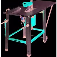
| Product type | Electric band saw |
| Brand | Einhell |
| Model | TCSB2001 |
| Mains voltage | 220-240 V ~ 50 Hz |
| Power | 250 W (S2 15 min) |
| No-load speed | 1400 rpm |
| Saw band length | 1400 mm |
| Saw band width | 7 mm (max 8 mm) |
| Saw band speed | 900 m/min |
| Max cutting height | 80 mm at 90°, 45 mm at 45° |
| Table dimensions | 305 x 305 mm |
| Table tilt | -2° to 45° |
| Weight | 17.5 kg |
| Sound pressure level | 84.3 dB(A) (K=3 dB) |
| Sound power level | 96 dB(A) (K=3 dB) |
| Delivery contents | Band saw, table, push stick, parallel fence, Allen keys 3/4/5 mm, anti-tilt protection, mounting hardware, instruction manual, safety instructions |
| Intended use | Cutting wood and similar materials lengthwise or crosswise |
| Maintenance and cleaning | Clean with a damp cloth and a little soap; do not use solvents |
| Warranty | 24 months |
| Wear parts | Guide roller, V-belt, saw band |
| Recommended accessories | Chip extraction device (not included) |
Frequently Asked Questions - TCSB2001 EINHELL
User questions about TCSB2001 EINHELL
0 question about this device. Answer the ones you know or ask your own.
Ask a new question about this device
Download the instructions for your Electric saw in PDF format for free! Find your manual TCSB2001 - EINHELL and take your electronic device back in hand. On this page are published all the documents necessary for the use of your device. TCSB2001 by EINHELL.
USER MANUAL TCSB2001 EINHELL
Danger! Read the operating instructions to reduce the risk of inquiry

Caution! Wear ear-muffs. The impact of noise can cause damage to hearing.

Caution! Wear a breathing mask. Dust which is injurious to health can be generated when working on wood and other materials. Never use the device to work on any materials containing asbestos!

Caution! Wear safety goggles. Sparks generated during working or splinters, chips and dust emitted by the device can cause loss of sight.

Pull the power plug before beginning any repair or maintenance work!

Saw blade cutting direction
Closing positions on the housing cover
GB
Danger!
When using the equipment, a few safety precautions must be observed to avoid injuries and damage. Please read the complete operating instructions and safety regulations with due care. Keep this manual in a safe place, so that the information is available at all times. If you give the equipment to any other person, hand over these operating instructions and safety regulations as well. We cannot accept any liability for damage or accidents which arise due to a failure to follow these instructions and the safety instructions.
1. Safety regulations
The corresponding safety information can be found in the enclosed booklet.
Danger!
Read all safety regulations and instructions. Any errors made in following the safety regulations and instructions may result in an electric shock, fire and/or serious injury. Keep all safety regulations and instructions in a safe place for future use.
2. Layout and items supplied
2.1 Layout (Fig. 1/2)
- ON/OFF switch
- Power cord
- Rubber tires
- Web panel
- Machine foot
- Extractor socket
- Lower blade pulley
- Upper blade pulley
- Tightening screw
- Blade guard
- Upper blade guide
- Side cover
- Hood closure
- Retaining screw for upper blade pulley
- Saw table
- Dial scale for tilt angle
- Plastic table insert
- Fixing handles for saw table
- Setting handle for blade guide
- Fixing handle for blade guide
- Clip for parallel stop
- Setting screw for upper blade pulley
- Motor
-
Parallel stop
-
Machine frame
26.Blade - Tilt guard
- Guide pin, top
- Guide pin, bottom
- Support bearing
- Support bearing
- Mount
- Sockethead screw
- Blade guard
- Allen screw
- Mount
- Sockethead screw
- Sockethead screw
- Hexagon key 3 mm
- Hexagon key 4 mm
- Screw
- Nut
43.Washer - Nut
- Push stick holder
- Push stick
- Screw
- Screw
- Rubber foot
- Hexagon key 5mm
- Screw
- Sockethead screw
53.Washer - Nut
55.Washer - Locking lever
- Cover
2.2 Items supplied
Please check that the article is complete as specified in the scope of delivery. If parts are missing, please contact our service center or the sales outlet where you made your purchase at the latest within 5 working days after purchasing the product and upon presentation of a valid bill of purchase. Also, refer to the warranty table in the service information at the end of the operating instructions.
- Open the packaging and take out the equipment with care.
- Remove the packaging material and any packaging and/or transportation braces (if available).
Check to see if all items are supplied. - Inspect the equipment and accessories for transport damage.
If possible, please keep the packaging until the end of the guarantee period.
GB
Danger!
The equipment and packaging material are not toys. Do not let children play with plastic bags, foils or small parts. There is a danger of swallowing or suffocating!
- Bandsaw
Saw table - Push stick
- Parallel stop
- Hexagon key 3 mm
- Hexagon key 4 mm
- Hexagon key 5 mm
Tilt guard
Assembly material
Original operating instructions
Safety information
3. Proper use
The bandsaw is designed to perform longitudinal and cross cuts on timber or wood-type materials. To cut round materials you must use suitable holding devices.
The equipment is to be used only for its prescribed purpose. Any other use is deemed to be a case of misuse. The user / operator and not the manufacturer will be liable for any damage or injuries of any kind caused as a result of this.
The machine is to be operated only with suitable saw blades. To use the machine properly you must also observe the safety regulations, the assembly instructions and the operating instructions to be found in this manual.
All persons who use and service the machine have to be acquainted with this manual and must be informed about the machine's potential hazards.
It is also imperative to observe the accident prevention regulations in force in your area. The same applies for the general rules of occupational health and safety.
The manufacturer shall not be liable for any changes made to the machine nor for any damage resulting from such changes. Even when the machine is used as prescribed it is still impossible to eliminate certain residual risk factors. The following hazards may arise in connection with the machine's construction and design:
- Damage to hearing if ear-muffs are not used as necessary.
- Harmful emissions of wood dust when used in closed rooms.
- Contact with the blade in the uncovered cutting zone.
Injuries (cuts) when changing the blade. - Injury from catapulted workpieces or parts of workpieces.
- Crushed fingers.
Kickback - Tilling of the workpiece due to inadequate support.
- Touching the blade.
- Catapulting of pieces of timber and workpieces.
Please note that our equipment has not been designed for use in commercial, trade or industrial applications. Our warranty will be voided if the machine is used in commercial, trade or industrial businesses or for equivalent purposes.
4. Technical data
Voltage: 220-240V 50 Hz
Power: .S2 15 min. 250 W
Ideal speed n_b .. 1400 min
Blade length: 1400 mm
Blade width: 7 mm
Max. blade width: 8 mm
Blade speed: 900 m/min
Cutting height: 80 mm / 90°
45mm/45°
Throat: 200 mm
Table size: 305 x 305 mm
Tilting range of table: -2° to 45°
Workpiece size: 400 x 400 x 80 mm
Weight: 17,5kg
Danger!
Sound and vibration
Sound and vibration values were measured in accordance with EN 61029.
LpA sound pressure level 84.3 dB(A)
K_BA uncertainty 3 dB
LWA sound power level 96 dB(A)
KNA uncertainty 3 dB
GB
Wear ear-muff s.
The impact of noise can cause damage to hearing.
Keep the noise emissions and vibrations to a minimum.
Only use appliances which are in perfect working order.
Service and clean the appliance regularly.
Adapt your working style to suit the appliance.
Do not overload the appliance.
- Have the appliance serviced whenever necessary.
- Switch the appliance off when it is not in use.
Caution!
Residual risks
Even if you use this electric power tool in accordance with instructions, certain residual risks cannot be rules out. The following hazards may arise in connection with the equipment's construction and layout:
- Lung damage if no suitable protective dust mask is used.
- Damage to hearing if no suitable ear protection is used.
5. Before starting the equipment
Make sure the machine stands securely, i.e. bolt it to a workbench or solid base. There are two holes for this purpose in the machine foot.
The saw table must be mounted correctly.
- All covers and safety devices have to be properly fitted before the machine is switched on.
It must be possible for the blade to run freely.
- When working with wood that has been processed before, watch out for foreign bodies such as nails or screws etc.
Before you actuate the On/Off switch, make sure that the saw blade is correctly fitted and that the machine's moving parts run smoothly.
Before you connect the machine to the power supply, make sure the data on the rating plate is the same as that for your mains.
6. Assembly
CAUTION!
Pull out the power plug before carrying out any maintenance, resetting or assembly work on the bandsaw!
6.1.1 Fitting the rubber feet / tilt guard (Fig. 5a/ 5b)
Secure the four rubber feet (49) to the bottom side of the equipment using the screw (51), the washer (43) and the nut (44).
Push the tilt guard (27) into the foot (5) and secure it to the equipment using the Sockethead screw (52), the washer (53) and the nut (54).
6.1.2 Mounting the saw table (Fig. 3 - 4)
- Remove the web panel (4).
- Place the saw table (15) onto the machine housing from the rear. Secure the saw table using the washers (55), the locking grip (18) and the locking lever (56).
To dismantle, proceed in reverse order.
6.2. Tensioning the blade (Figure 1)
CAUTION! Remove the tension from the blade if the bandsaw is not going to be used for some time. Be sure to re-tension the blade before you start the machine.
- Turn the tightening screw (9) for tensioning the blade (26) in a clockwise direction.
The correct blade tension can be checked by applying pressure to the side of the blade with your finger, somewhere in the middle between the two blade pulleys (7 + 8) . You should only be able to bend the blade (26) very slightly (approx. 1 - 2mm ).
- When the blade is tensioned enough, it will produce a metallic sound when tapped.
Take the tension off the blade when you do not want to use it for some time; this will help to prevent overstretching.
- Caution! The blade may break if the tension is too high. BEWARE OF INJURY! If the tension is too low, the powered blade pulley (7) will spin while the blade does not move.
6.3 Adjusting the blade (fi g. 1-2)
CAUTION! The blade tension has to be set correctly before you can adjust the blade.
- Undo the fasteners (13) and open the side cover (12).
Turn the upper blade pulley (8) slowly in a
GB
clockwise direction. The blade (26) should run with its teeth at the front edge of the tire on the blade pulley (8). If not, the tilt angle of the upper blade pulley (8) must be corrected.
If the blade (26) tends to run to the back of the blade pulley (8), i.e. towards the machine frame (25), turn the setting screw (22) anticlockwise while turning the blade pulley (8) by hand until the blade (26) runs in the middle.
If the blade (26) tends to run to the front edge of the blade pulley (8), turn the setting screw (22) in a clockwise direction.
After setting the upper blade pulley (8) you need to check the blade (26) position on the lower blade pulley (7). The blade (26) should run in the middle of the blade pulley (7), as above. If it does not, you will have to adjust the tilt of the upper blade pulley (8) again.
- Turn the upper blade pulley several times until the adjustment to the upper blade pulley (8) has an effect on the blade position of the lower blade pulley (7).
After any adjustments have been carried out, the side covers (12) must be closed again and re-secured with the fasteners (13).
6.4. Setting the blade guide (Fig. 7 - 10)
Whenever you change the blade you must re-set both the support bearings (30 + 31) and the guide pins (28 + 29) .
- Undo the fasteners (13) and open the side cover (12).
6.4.1. Upper support bearing (30)
Undo the screw (33).
- Move the support bearing (30) so that it is no longer touching the blade (26). There should be a maximum gap of 0.5 mm .
Re-tighten the screw (33).
6.4.2. Adjusting the lower support bearing (31)
- Remove the saw table (15) or tilt it 45^ .
Swing the blade guard (34) away. - Adjust in the same way that the upper support bearing was adjusted. The blade (26) is only supported by the support bearings (30 + 31) during cutting. When idle the blade should not touch the ball bearing.
6.4.3. Adjusting the upper guide pins (28)
- Undo the Sockethead screw (35)
- Move the mount (36) of the guide pins (28) so that there is a gap of approx. 1mm between the front edge of the guide pins (28) and the
GB
6.6. Adjusting the saw table (15) to 90^ (12/13)
- Slacken the locking grip (18) and the locking lever (56) and open the cover at the blade guide (11).
- Place the angle (d) between the blade (26) and the table (15). The angle (d) is not included in delivery.
- Tilt the saw table (15) by turning it so that the angle between it and the blade (26) is precisely 90^ .
- Tighten the locking grip (18) and the locking lever (56) again and close the cover at the blade guide (11).
Slacken the nut (42). - Adjust the screw (41) until there is contact with the machine housing.
- Re-tighten the nut (42) to fasten the screw (41).
6.7.Blade selection
The blade supplied with the bandsaw is designed for all-purpose use. When you select a blade you should have regard to the following criteria:
Use a narrow blade to cut tighter radii than you can with a wider blade.
- Wide blades are used to saw straight cuts. This is particularly important in cutting wood because the blade has a tendency to follow the grain of the wood and thereby deviate easily from the cutting line.
- Finely toothed blades provide smoother cuts but are slower than coarse blades.
Caution! Never use warped or lacerated blades!
6.8. Changing the saw blade (Fig. 1/14a/14b)
- Remove the cover (57)
- Move the blade guide (11) into a position approximately half way between the table (15) and the machine housing (25).
- Undo the fasteners (13) and open the side cover (12).
- Remove the web panel (4).
- Turn the tightening screw (9) counterclockwise to remove the tension from the blade (26).
- Remove the blade (26) from the blade pulleys (7,8) and take out through the slot in the table (15).
-
Fit the new blade (26), aligned centrally on the blade pulleys (7,8). The teeth of the blade (26) must point downwards in the direction of the table.
Tension the blade (26) (see 6.2). -
Close the side cover (12) again.
- Mount the web panel (4) again.
Refit the cover.
6.9. Changing the rubber tires on the blade pulleys (Figure 15)
After a certain time the rubber tires (3) on the blade pulleys (7/8) will get worn by the sharp teeth of the blades and must be replaced.
Open the side cover (12).
- Remove the blade (26) (see 6.8).
- Lift the edge of the tire (3) with a small screwdriver (f) and then pull it off the upper blade pulley (8).
Repeat for the lower blade pulley (7).
- Fit the new tire (3), replace the blade (26) and close the side cover (12).
6.10. Changing the table insert (Figure 16)
To prevent increased likelihood of injury the table insert (17) should be changed whenever it is worn or damaged.
- Undo the fastening screw of the table insert (17) using a Phillips screwdriver (h). (The Phillips screwdriver is not included in delivery.)
- Lift out the worn table insert (17).
- Fit the replacement table insert by following the above in reverse.
6.11.Extractor sockets (fIg.2)
The bandsaw is equipped with extractor sockets (6) for extracting sawdust and chips.
Connect the bandsaw to a chip extraction system (not included in delivery) by connecting the hose of the extraction system to the extractor socket (6).
6.12. Push stick holder (Fig. 6)
- When not in use, the push stick must always be kept on the holder.
7. Control elements
7.1. On/Off switch (Figure 17)
To turn the machine on, press the green button 1^+
To turn the machine off again, press the red button 0^
- Your bandsaw has a switch with undervoltage release. After a power failure you must re-activate the switch.
7.2. Parallel stop (Figure 18)
- Push the clip (21) on the parallel stop (24) upwards.
- Move the parallel stop (24) along the table (15), from either the right or left of the blade (26), and position as required.
- Push the clip (21) down to fix the parallel stop (24). If the clip (21) does not give enough hold, turn it clockwise several times until the parallel stop is securely fixed.
- You must always ensure that the parallel stop (24) is positioned parallel to the blade (26).
7.3.Angular cuts (Abb.19)
To enable you to perform angular cuts parallel to the blade (26), the table (15) can be tilted forwards between 0^ - 45^ .
- Undo the fixing handles (18).
- Tilt the saw table (15) forwards until the required angle value is set on the dial scale (16).
Re-tighten the fixing handles (18). - Important: When the table (15) is tilted, place the parallel stop (24) to the right of the blade (26) looking in the direction in which you are working, on the side pointing downwards (provided the workpiece is wide enough) in order to stop the workpiece from slipping off.
8. Operation
Caution! After every new adjustment we recommend you to make a trial cut in order to check the new settings.
For all cutting operations it is important to position the blade guide (11) as close as possible to the workpiece (see 6.5).
Always guide the workpiece with both hands, holding it flat on the table (15) in order to prevent the blade (26) from jamming.
Feed the workpiece at a uniform speed that enables the blade to cut through the material without difficulty and without blocking.
Always use the parallel stop (24) on all cuts for which they are intended.
Always aim at making a complete cut in one pass rather than in a stop-and-go operation requiring the workpiece to be withdrawn. If you have to withdraw the workpiece, switch off the bandsaw first and wait for the blade (26) to stop before freeing the workpiece.
The workpiece must always be guided by the longer side during cutting.
Important! When handling narrower workpieces, it is essential to use a push stick. The push stick (28) must always be kept close at hand at the hook (29) provided for that purpose on the side of the saw.
8.1. Longitudinal cuts (Figure 20)
Longitudinal cutting is when you use the saw to cut along the grain of the wood.
- Place the parallel stop (24) to the left of the blade (25), as far as possible, for the width required.
Lower the blade guide (11) down to the workpiece (see 6.5). - Switch on the saw.
- Press the edge of the workpiece with your right hand to hold it securely against the parallel stop (24) and flat on the table (15).
- Guide the workpiece along the parallel stop (24) and through the blade (26) at a uniform speed.
Danger! Long workpieces must be secured against falling off at the end of the cut (e.g. with a roller stand etc.)
8.2. Making angular cuts (Fig. 19)
- Set the saw table to the desired angle (see 7.3).
- Carry out the cut as described in 8.1.
8.3.Freehanded cuts (Figure 21)
One of the most outstanding features of a band-saw is the ease with which it allows you to make curved cuts and radii.
Lower the blade guide (11) to the workpiece (see 6.5).
- Switch on the saw.
Hold the workpiece securely on the table (15) and guide slowly through the blade (26).
Freehanded cuts should be made at low feed speed so that you can guide the blade (26) along the required line.
It often pays to first cut off surplus curves and corners up to about 6 mm from the cutting line.
In the case of curves which are too tight for the blade to cut correctly, it can help to make a series of close-lying cuts at right angles to the curved line. When you saw the radius the material will simply drop off.
GB
9. Transport
To transport the bandsaw, hold the supporting foot (5) with one hand and the frame (25) with the other hand. Important! Never use guards to lift or transport the equipment.
and plastic. Never place defective equipment in your household refuse. The equipment should be taken to a suitable collection center for proper disposal. If you do not know the whereabouts of such a collection point, you should ask in your local council offices.
10. Cleaning, maintenance and ordering of spare parts
Danger!
Always pull out the mains power plug before starting any cleaning work.
12. Storage
Store the equipment and accessories out of children's reach in a dark and dry place at above freezing temperature. The ideal storage temperature is between 5 and 30^ . Store the electric tool in its original packaging.
10.1 Cleaning
- Keep all safety devices, air vents and the motor housing free of dirt and dust as far as possible. Wipe the equipment with a clean cloth or blow it with compressed air at low pressure.
We recommend that you clean the device immediately each time you have finished using it.
Clean the equipment regularly with a moist cloth and some soft soap. Do not use cleaning agents or solvents; these could attack the plastic parts of the equipment. Ensure that no water can seep into the device. The ingress of water into an electric tool increases the risk of an electric shock.
10.2 Maintenance
There are no parts inside the equipment which require additional maintenance.
10.3 Ordering replacement parts:
Please quote the following data when ordering replacement parts:
Type of machine
Article number of the machine
- Identification number of the machine
- Replacement part number of the part required For our latest prices and information please go to www.isc-gmbh.info
11. Disposal and recycling
The equipment is supplied in packaging to prevent it from being damaged in transit. The raw materials in this packaging can be reused or recycled. The equipment and its accessories are made of various types of material, such as metal
GB

For EU countries only
Never place any electric power tools in your household refuse.
To comply with European Directive 2012/19/EC concerning old electric and electronic equipment and its implementation in national laws, old electric power tools have to be separated from other waste and disposed of in an environment-friendly fashion, e.g. by taking to a recycling depot.
Recycling alternative to the return request:
As an alternative to returning the equipment to the manufacturer, the owner of the electrical equipment must make sure that the equipment is properly disposed of if he no longer wants to keep the equipment. The old equipment can be returned to a suitable collection point that will dispose of the equipment in accordance with the national recycling and waste disposal regulations. This does not apply to any accessories or aids without electrical components supplied with the old equipment.
The reprinting or reproduction by any other means, in whole or in part, of documentation and papers accompanying products is permitted only with the express consent of the iSC GmbH.
Subject to technical changes
GB
Service information
We have competent service partners in all countries named on the guarantee certificate whose contact details can also be found on the guarantee certificate. These partners will help you with all service requests such as repairs, spare and wearing part orders or the purchase of consumables.
Please note that the following parts of this product are subject to normal or natural wear and that the following parts are therefore also required for use as consumables.
| Category Example | |
| Wear parts* Guide roller, V-belt | |
| Consumables* Bandsaw blade | |
| Missing parts |
- Not necessarily included in the scope of delivery!
In the effect of defects or faults, please register the problem on the internet at www.isc-gmbh.info. Please ensure that you provide a precise description of the problem and answer the following questions in all cases:
Did the equipment work at all or was it defective from the beginning?
Did you notice anything (symptom or defect) prior to the failure?
- What malfunction does the equipment have in your opinion (main symptom)?
Describe this malfunction.
GB
Warranty certificate
Dear Customer,
All of our products undergo strict quality checks to ensure that they reach you in perfect condition. In the unlikely event that your device develops a fault, please contact our service department at the address shown on this guarantee card. You can also contact us by telephone using the service number shown. Please note the following terms under which guarantee claims can be made:
- These guarantee terms apply to consumers only, i.e. natural persons intending to use this product neither for their commercial activities nor for any other self-employed activities. These warranty terms regulate additional warranty services, which the manufacturer mentioned below promises to buyers of its new products in addition to their statutory rights of guarantee. Your statutory guarantee claims are not affected by this guarantee. Our guarantee is free of charge to you.
- The warranty services cover only defects due to material or manufacturing faults on a product which you have bought from the manufacturer mentioned below and are limited to either the rectification of said defects on the product or the replacement of the product, whichever we prefer. Please note that our devices are not designed for use in commercial, trade or professional applications. A guarantee contract will not be created if the device has been used by commercial, trade or industrial business or has been exposed to similar stresses during the guarantee period.
-
The following are not covered by our guarantee:
-
Damage to the device caused by a failure to follow the assembly instructions or due to incorrect installation, a failure to follow the operating instructions (for example connecting it to an incorrect mains voltage or current type) or a failure to follow the maintenance and safety instructions or by exposing the device to abnormal environmental conditions or by lack of care and maintenance.
- Damage to the device caused by abuse or incorrect use (for example overloading the device or the use or unapproved tools or accessories), ingress of foreign bodies into the device (such as sand, stones or dust, transport damage), the use of force or damage caused by external forces (for example by dropping it).
-
Damage to the device or parts of the device caused by normal or natural wear or tear or by normal use of the device.
-
The guarantee is valid for a period of 24 months starting from the purchase date of the device. Guarantee claims should be submitted before the end of the guarantee period within two weeks of the defect being noticed. No guarantee claims will be accepted after the end of the guarantee period. The original guarantee period remains applicable to the device even if repairs are carried out or parts are replaced. In such cases, the work performed or parts fitted will not result in an extension of the guarantee period, and no new guarantee will become active for the work performed or parts fitted. This also applies if an on-site service is used.
-
To make a claim under the guarantee, please register the defective device at: www.isc-gmbh.info. Please keep your bill of purchase or other proof of purchase for the new device. Devices that are returned without proof of purchase or without a rating plate shall not be covered by the guarantee, because appropriate identification will not be possible. If the defect is covered by our guarantee, then the item in question will either be repaired immediately and returned to you or we will send you a new replacement.
Of course, we are also happy offer a chargeable repair service for any defects which are not covered by the scope of this guarantee or for units which are no longer covered. To take advantage of this service, please send the device to our service address.
Also refer to the restrictions of this warranty concerning wear parts, consumables and missing parts as set out in the service information in these operating instructions.
F

Chere cliente, cher client,
Duljina trake pile: 1400 mm
Sirina trake pile: 7 mm
Sirina trake pile maks: 8 mm
Brzina trake pile: 900 m/min
Visina rezanja: 80 mm / 90°
45mm/45°
Polumjer rada: 200 mm
Veličina stola: 305 x 305 mm
Nagib stola: -2° do 45°
Veličina radnog
komada maks.: 400 x 400 x 80 mm
Težina: 17,5kg
Opasnost!
Buka i vibracije
5. Pre puštanja u pigeon
Mašina mora da se postavi stabilno, šta znači pričvsti na radni sto ili stabilno postolje. Za tu svruho na nogarima mašine nalaze se rupe za pričvřsčivanje.
Sto testere mora da se montira pravilno.
Pre pušanja u rad moraju propisno da se montiraju svi Poklopci i sigurnosne naprave.
Traka testere mora slobodno da se krece.
- Drvo koje cete obradivati proverite na eventuINo zaostala strana tela, kao npr. eksere ili zavrtnje i sl.
Pre nego ukljucite prekida za ukljucivanje/ iskljucivanje proverite da li je list testere pravilno montiran i da li se glibljivi delovi lakpokrecu.
Preprikljucivanja masine proverite da li podaci na tipskoj ploci odgovaraju podacima o mrezi.
6. Montaža
PAZNJA!
Pre svih radova odrzavanja i preinačavanja na testeri treba da izvučete mrežni utikač.
6.1.1 Montaza gumenih nozica/zastite od pre-vrtanja (slika 5a/5b)
Fiksirajte Četiri gumene nožice (49) sa zavrtnjem (51), podloškom za podmetanje (43) i navrtkom (44) na donju stranu uredaja.
Gurnite zastitu od prevrtanja (27) u nogar (5) i fiksirajte je na uredjai imbus zavrtnjem (52), podloznom podloskom (53) i navrtkom (54).
6.1.2 Montaza stola testere (sl. 3-4)
Izvadite limeni mostic (4)
- Stavite stol testere (15) na străznju stranu kučista masine. Pricvrstite ga pločicama za podmetanje (55), ruckom za fiksiranje (18) i polugom za fiksiranje (56).
- Demontaža se vrši obrutim redom.
6.2. Napinjanje trake testere (sl.1)
- PAZNJA! Kod dužeg mirovanja testere morate da opustite traku testere, šta znaci da pre ponovnog uključivanja morate da proverite napetost trake.
- Okrenite zavrtanj (9) za napinjanje trake testere (26) u smeru skazaljke na casovniku.
- Pravilna napetost trake testere moze se utvr-diti bočnim pritiskom prsta na traku, negde na sredini izmedu koloturnika (7 + 8) . Pritom traketestere (26) sme da se savine samo malo (oko 1 - 2mm ).
Dovoljno zategnuta traka testere daje metalni zvuk dok se dotakne prstima. - Otpustite traku testere ako necete da je koristite duze vreme takao da se ne rastegne.
- Oprez! Ako je traka previse napeta, moze da pukne. OPASNOST OD POVREDE! Kod pre-male napetosti pogonjeni koloturnik (7) moze da proklizuje, pri cemu traka testere ostaje mirovati.
6.3 Podesavanje trake testere (sl. 1-2)
- PAZNJA! PreNgu sto cete pocti s podešavanjem, traka testere mora da bude pravilno napeta.
- OtvoritebočnePoklopce (12) otpušanjem brava (13).
Gornji kotur s trakom (8) lagano obricle u smeru kazaljke na casovniku. Traka testere
RS
(26) mora se kretati sa zupcima na prednjoi ivici radne povrsine kotura za traku (8).Ako to nije takto, morate korigovati ugao nagiba gorn-jeg kotura (8).
Ako se traka (26) krece više prema zadnjoj strani koloturnika (8), šta znači u smeru kučišta masine (25), zavrtanj za poděsavanje (22) mora da se okrece u smeru protivnom od skazaljke na casovniku, pri Čemu koloturnik (8) lagano obrćete drugom rukom kako bist proverili položaj trake (26).
Ako se traka (26) krece vihe prema prednjoj ivici koloturnika (8), zavrtanj za podesavanje (22) obrcite u smeru skazaljke na casovniku.
- Nakon podesavanja gornjeg koloturnika (8) proverite položaj trake (26) na donjem koloturniku (7). Traka testere (26) trebala bitakode da bude u sredini koloturnika (7). Akoto nodsučaj, još Jednomora da se kriguje ugao nagiba gornjeg koloturnika (8).
Da bi se videla korekcija gornjeg koloturnika (8) s obzirom na položaj trake na donjem koloturniku (7), nekoliko puta okrenite koloturnik za traku.
Nakon uspešnog podesavanja ponovo zatvo-rite bočnePoklopce (12)i osiguraje ih bravama (13).
6.4.Podesavanje vodice trake testere (sl.7-10)
Potporni lezajevi (30 + 31) kao i klinovi vodice (28
+29) moraju da se podese nakon svake zamene trake testere.
- OtvoritebočnePoklopce (12) OTPustanjem brava (13).
6.4.1. Gornji potporni lezaj (30)
- Otpustite zavrtanj (33)
Potporni lezaj (30) gurnite toliko da ne dodiruje vishe traku testere (26) (odstojanje maks. 0,5 mm) - Ponovno stegnite zavrtanj (33).
6.4.2. Podesavanje donjeg potpornog lezaja (31)
Sto testere (15) demontirati ili staviti pod nagib od 45^ .
- Otklopite zašitu lista testere (34).
- Podešavanje je jegnako kao za gornji potpörni ležaj. Oba potporna ležaja (30 + 31) podupiru traku testere (26) sam tokom postupka rezanja. U praznom hodu traka testere ne bi smela da dotice kuglicni ležaj.
6.4.3. Podesavanje gornjih klinova vodice (28)
Otpustite imbus zavrtanj (35)
- Pomerite prihvatni držac (36) klinova vodice (28) tak, da prednja ivica klinova (28) bude oko 1 mm iza baze zupca trake testere.
- Ponovno stegnite imbus zavrtanj (35).
- PAZNJA!Trakaçé postati neupotrebljiva akó
će zupci doticati klinove vodice dok mašina
radi.
Olabavite imbus zavrtnje (37).
- Oba klna vodice (28) gurnite u smeru trake, takdo odstoanje izmedu klinova vodice (28) i trake (26) bude maks. 0,5 mm. (traka testere ne sme da zapinje)
- Ponovno stegnite imbus zavrtnje (37).
Gornji koloturnik za traku (8) nekoliko puta okrenite u smeru skazalike na calsovnik.
Još Jednom proverite podeşenost klinová vodice (28) i po potrebi inh korigujte.
6.4.4. Podesavanje donjih klinova vodice (29)
- Demontirajte sto testere (15)
Olabavite zavrtanj (48) - Pomaknite prihvatni drzač (32) klinova vodice (29) takó, da prednji rub klinova (29) bude oko 1 mm iza baze zupca trake testere.
- Ponovno stegnite zavrtanj (40).
- PAZNJA!Trakace postati neupotrebljiva ako ce zupci dotici klinove vodice dok masina radi.
Olabavite zavrtnje (38). - Oba klna vodice (29) gurnite u smeru trake, takdo razmak izmedu klinova vodice (29)i trake (26) bude maks. 0,5 mm.(traka testere ne sme da zapinje)
- Ponovo stegnite imbus zavrtnje (38).
- Donji koloturnik za traku (7) nekoliko puta okrenite u smeru skazaljke na casovnik.
Još Jednom proverite podeşenost klinová vodice (29) i po potrebi inh korigujte.
6.5.Podesavanje gornje vodice trake testere (11) (sl. 11)
- Otpustiterucicu za fiksiranje (20).
- Okretanjemtočka za podesavanje (19) spustite vodicu trake testere (11) što je moguce blize materijalu koji rezete (razmak oko 2-3 mm).
- Ponovno stegnite ručicu za fiksiranje (20).
Pre svakog postupka rezanja proverite podesenost i po potrebi izvrsite korekciju.
RS
6.6. Podesavanje stola testere (15) za 90^ (12/13)
- Otpustite ručku za fiksiranje (18) i polugu za fiksiranje (56) i otvoritePoklopac vodice trake testere (11).
- Namestite ugaonik (d) izmedu trake testere (26) i stola (15). Sadržina isporuke ne obuhvata ugaonik (d).
- Okrecite sto testere (15) toliko da ugao izmedu njega i trake testere (26) bude tačno 90°.
- Povucite ručku za fiksiranje (18) i polugu za fiksiranje (56) i zatvoritePoklopac vodice tra- ke testere (11).
- Otpustite navrtku (42).
- Okrecite zavrtanj (41) toliko da dotakne kuciiste masine.
- Ponovno stegnite navrtku (42) da biste fiksirli zavrtanj (41).
6.7. Koju traku testere koristiti
GB explains the following conformity according to EU directives and norms for the following product
Subject to change without notice
Archive-File/Record: NAPR012470
Documents registrar: Roider Siegfried
Wiesenweg 22, D-94405 Landau/Isar
EH 03/2017 (03)


- GB
- Danger!
- Safety regulations
- Layout and items supplied
- Layout (Fig. 1/2)
- Items supplied
- Proper use
- Technical data
- Sound and vibration
- Wear ear-muff s.
- Keep the noise emissions and vibrations to a minimum.
- Caution!
- Residual risks
- Even if you use this electric power tool in accordance with instructions, certain residual risks cannot be rules out. The following hazards may arise in connection with the equipment's construction and layout:
- Before starting the equipment
- Assembly
- Fitting the rubber feet / tilt guard (Fig. 5a/ 5b)
- Mounting the saw table (Fig. 3 - 4)
- Tensioning the blade (Figure 1)
- Adjusting the blade (fi g. 1-2)
- Setting the blade guide (Fig. 7 - 10)
- Upper support bearing (30)
- Adjusting the lower support bearing (31)
- Adjusting the upper guide pins (28)
- 6.7.Blade selection
- Control elements
- Parallel stop (Figure 18)
- 7.3.Angular cuts (Abb.19)
- Operation
- Longitudinal cuts (Figure 20)
- Making angular cuts (Fig. 19)
- 8.3.Freehanded cuts (Figure 21)
- Transport
- Cleaning, maintenance and ordering of spare parts
- Storage
- Cleaning
- Maintenance
- Ordering replacement parts:
- Disposal and recycling
- Service information
- Warranty certificate
- Dear Customer,
- F
- Opasnost!
- Buka i vibracije
- Pre puštanja u pigeon
- Montaža
- PAZNJA!
- Montaza gumenih nozica/zastite od pre-vrtanja (slika 5a/5b)
- Montaza stola testere (sl. 3-4)
- Napinjanje trake testere (sl.1)
- Podesavanje trake testere (sl. 1-2)
- RS
- 6.4.Podesavanje vodice trake testere (sl.7-10)
- Gornji potporni lezaj (30)
- Podesavanje donjeg potpornog lezaja (31)
- Podesavanje gornjih klinova vodice (28)
- Podesavanje donjih klinova vodice (29)
- 6.5.Podesavanje gornje vodice trake testere (11) (sl. 11)
- Podesavanje stola testere (15) za 90° (12/13)
- Koju traku testere koristiti
Brand : EINHELL
Model : TCSB2001
Category : Electric saw