FUSG50101 - Alarm system ABUS - Free user manual and instructions
Find the device manual for free FUSG50101 ABUS in PDF.
| Product type | Wireless outdoor siren with strobe |
| Brand | ABUS |
| Model | FUSG50101 |
| Dimensions (W×H×D) | 210.6 × 294 × 78.5 mm |
| Weight | 1.2 kg (without batteries), 2.6 kg (with batteries) |
| Protection rating | IP65 (when mounted) |
| Operating temperature | -25°C to +60°C |
| Sound pressure | 100 dB(A) at 1 m |
| Power supply | 6 V DC, 2 alkaline-manganese batteries 3 V / 18 Ah |
| Battery life | 2 years nominal (for 1 activation/month of 3 min) |
| Radio frequency | 868.6625 MHz |
| Max radio range | 500 m in open field |
| Security level | Level 2 (EN 50131-1) |
| Main functions | Audible and visual alarm, 2 siren tones + fire alarm, acknowledgment beep, sabotage detection (opening, removal), jamming monitoring, high-performance LED flash, integrated spirit level |
| Maintenance | External cleaning, check tamper contacts, battery replacement every 2 years |
| Spare parts | Replacement batteries: reference FU2986 (2 battery packs) |
| Warranty | 2 years (material or manufacturing defects) |
Frequently Asked Questions - FUSG50101 ABUS
User questions about FUSG50101 ABUS
0 question about this device. Answer the ones you know or ask your own.
Ask a new question about this device
Download the instructions for your Alarm system in PDF format for free! Find your manual FUSG50101 - ABUS and take your electronic device back in hand. On this page are published all the documents necessary for the use of your device. FUSG50101 by ABUS.
USER MANUAL FUSG50101 ABUS
Installation instructions and user manual
FR
Installation instructions and user manual
FR
Information on user manual 22
Intended use 22
Limitation of liability 22
Safety information 23
Explanation of symbols 23
Packaging 23
Battery warning information 23
Scope of delivery 24
Technical Data 24
Functional principle and features 25
General 25
Main features 26
Device description 27
Installation 28
Installing the sounder 28
Functions, jumpers and displays 32
Installer mode 32
Jumper and battery connector 32
Operation of the comfort LEDs 34
Operation of the flashing light 35
Error and tamper monitoring 35
Maintenance 36
Warranty 37
Disposal 37
Declaration of conformity 37
Introduction
Information on user manual
Dear Customer,
Thank you for purchasing this product. This device is built with state-of-the-art technology. This manual contains important installation and operation information (last updated 01/2018 with software V1.10.2). Follow the directions and instructions in this user manual to ensure safe operation. Store this manual in a safe place for future reference. This manual constitutes part of the device. If you pass the device on to third parties, please remember to include this manual.
Intended use
Only use the device for the purpose for which it was built and designed. Any other use is considered unintended.
This product complies with current domestic and European regulations. Conformity has been proven, and all related certifications are available from the manufacturer on request.
To ensure this condition is maintained and that safe operation is guaranteed, it is your obligation to observe this user manual. If you have any questions, please contact your specialist dealer. Further general information and information on product support can be found at www.abus.com on the general page or for dealers and installers, in the Partner portal.

Note:
Please observe the notes and instructions in this user manual! If you do not follow these instructions, any guarantee claim is invalidated. No liability can be accepted for resulting damage. No part of the product may be changed or modified in any way.
Please observe the local legal requirements. In some European countries, the use of alarms outdoors is prohibited or the maximum alarm duration is limited. Please consult your local authorities on this.

Caution and Important
When inserting the batteries in the sounder, the acoustic alarm may emit a loud sound. This may startle you. Make sure that you don't lose your balance or drop the sounder.
Limitation of liability
Everything possible has been done to ensure that the content of these instructions is correct. However, neither the author nor ABUS Security-Center GmbH & Co. KG can be held liable for loss or damage caused by incorrect or improper installation and operation or failure to observe the safety instructions and warnings. No liability can be accepted for resulting damage. No part of the product may be changed or modified in any way. If you do not follow these instructions, your warranty claim becomes invalid.
Subject to technical modifications.
© ABUS Security-Center GmbH & Co. KG, 01/2018
Safety information
Explanation of symbols
The following symbols are used in this manual and on the device:
| Symbol | Signal word | Meaning |
| ! | Caution | Indicates a risk of injury or health hazards. |
| Caution | Indicates a risk of injury or health hazards caused by electrical voltage. | |
| Important | Indicates possible damage to the device/accessories. | |
| i | Note | Indicates important information. |
| The EU Directive WEEE 2012/19/EC governs the proper recovery, treatment and recycling of used electronic devices. This symbol means that, in the interest of environmental protection, the device must be disposed of separately from household or industrial waste at the end of its lifespan in accordance with applicable local legal guidelines. Used devices can be disposed of at official recycling centres in your country. Obey local regulations when disposing of material. Further details on returns (also for non-EU countries) can be obtained from your local authority. Separate collection and recycling conserve natural resources and ensure that all the provisions for protecting health and the environment are observed when recycling the product. |
Packaging

Caution
- Keep packaging material and small parts away from children. There is a risk of suffocation.
- Remove all packaging material before using the device.
Battery warning information

Caution
The device is supplied with direct current from a battery pack. To guarantee a long lifespan and avoid fire and injury, please note the following:
- Do not dispose of the battery with household waste.
- The battery must not be directly exposed to heat or sunlight, and must not be stored in hot places.
- The battery must not be burned.
- The battery must not come into contact with water.
-
The battery must not be dismantled, pierced or otherwise damaged.
-
The battery contacts must not be short-circuited.
- The battery must be kept away from small children.
- The battery cannot be recharged.
Scope of delivery
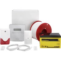
Secvest Wireless Outdoor Sounder
-
2 × battery pack
-
Quickstart guide with important product information
Installation material
Technical Data
| ·Product name | Secvest Wireless Outdoor Sounder |
| ·Product description | Sounder |
| ·Item number | FUSG50101 |
| ·Manufacturer | ABUS Security-Center GmbH & Co. KG |
| ·Environmental class | IV (EN 50131-1 + A1:2009 Section 7) |
| ·Protection class, IP protection class | IP65 (in installed state) IP = international protection or ingress protection 6 = complete protection against contact 5 = protection from jets of water (from a nozzle) from any angle |
| ·Operating temperature | -25°C to +60°C |
| ·Humidity, maximum | max. 95% |
| ·Housing material | Polycarbonate |
| ·Dimensions (W x H x D) | 210.6 x 294 x 78.5 mm |
| ·Weight | 1.2 kg (without batteries) 2.6 kg with batteries 2 x 0.7 kg batteries alone (0.7 kg per battery pack) |
| ·Security level | Grade 2 (EN 50131-1 + A1:2009 Section 6) |
| ·Flashing frequency | Double flash @ approx. 1 Hz |
| ·Sound pressure | 100 dB(A) @ 1 m |
| ·Tones | 2 x normal alarm, fire alarm, perimeter warning, acknowledgement beep |
| ·Maximum duration of the acoustic alarm | 15 minutes |
| ·Power supply type | Cable type W (EN 50131-4:2009 Section 5.6.3.2) |
| ·Type of power supply | Type C relating to EN 50131-1 Section 9 and EN 50131-6 Section 4.1 |
| • Power consump- tion/energy con- sumption | Standby current including comfort LEDs 0.25 mA Siren sounding alarm 225 mA |
| • Normal voltage | 6 V DC |
| • Battery type | 2 x 3 V alkaline manganese batteries, 18 Ah Item number of the replacement batteries: FU2986 (comprises 2 battery packs) |
| • Battery life | 2 years nominal With one activation per month for 3 minutes. Flashing and audio alarm With one arming acknowledgement per day. Acknowledgement flash and beep With one disarming acknowledgement per day. Acknowledgement flash and beep |
| • Battery under vol- tage threshold | 4.5 V “Flat battery” fault at <4.5 V |
| • Operating frequency | 868.6625 MHz narrow band |
| • Receiving range | Max. 500 m range outdoors |
| • Standards for intru- sion and panic but- ton devices | EN 50131-4:2009 PD6662:2010 |
| • EU Directives | R&TTE: 1999/5/EC EMC: 2004/108/EC RoHS: 2011/65/EC WEEE: 2012/19/EC EuP: 2005/32/EC Low Voltage: 2006/95/EC General Safety: 2001/95/EC |
| • General | This product must be installed by a qualified service engineer. |
Functional principle and features
General
The Wireless Outdoor Sounder is an outdoor combination alarm device with siren and flashing light for use with Secvest alarm panels. It serves as an optical and acoustic alarm. The sounder and alarm panel communicate with each other wirelessly, so no fixed wiring is required between the two units. The Wireless Outdoor Sounder is battery operated (self-powered) and is intended for wall installation.
Main features
| Simple installation | Installer mode (remains silent when opened) |
| 100 dB(A) sound pressure | Monitors battery voltage |
| 500 m range outdoors | Cover and wall tamper contact |
| High-performance comfort LEDs | Selectable off-switch timer |
| High-performance LED flashing lights | 2 different normal alarm sounds can be se- lected |
| Integrated spirit level | 2 normal alarm tones, 1 fire alarm tone, tone for perimeter warning, acknowledgement beep |
| Hinged lid for easy installation | Shock-resistant construction from polycar- bonate |
| Jamming detection |

- Before starting installation, identify a suitable installation location for the Wireless Outdoor Sounder using the wireless test box. Ensure that the sounder is installed out of hand's reach (minimum 3 m installation height). In addition, the sounder should be visible and audible from afar.
- Incorrect or unclean installation work may lead to erroneous interpretation of signals. The consequences of which may include false alarms. The costs incurred by potential dispatches of rescue services, such as the fire service or police, must be borne by the operator of the system.
To ensure trouble-free operation, the sounder must NOT be installed:
- close to large metal structures, such as metal doors or frames, water tanks, vehicles and refrigerators
- close to the main power supply, or close to water or gas pipelines
- inside a metal housing
- next to electronic devices, especially computers, photocopiers and radios.
- Switch the Secvest alarm panel to installer mode before starting any installation or maintenance work. Installer mode prevents the sounder and the flashing light from being activated when the sounder's cover is opened. This prevents you being startled because the sounder remains silent.
Device description
1 Lid fixing screw with cover
2 Mounting hole for wall installation
3 Mounting holes for tamper mechanism
4 Spirit level
5 Jumper/connector cover
6 Fixing tab for the jumper/connector cover
To unlock: Push the tabs on both sides outwards
7 Jumpers and battery connectors
8 Battery
9 Tamper switch
10 Anti-removal wall contact; length of the pin can be adjusted
11 Acoustic sounder
12 Flashing LED
13 Comfort LED
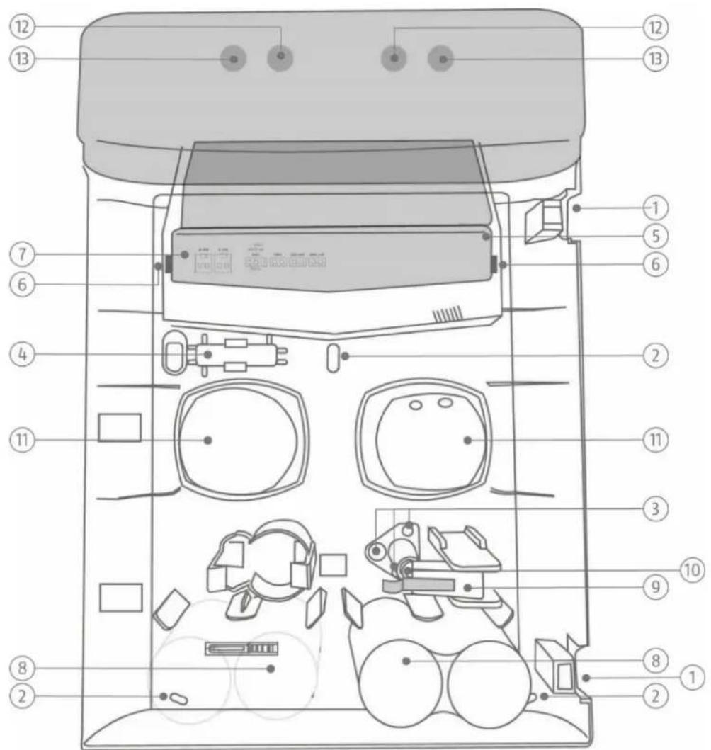
Figure 1: Overview of the sounder
Installation
Installing the sounder
Step 1: Select installation location for the sounder
Select an installation location which:
- is inaccessible to intruders and vendors
- is located well out of reach (>3m)
- is clearly visible, so that it acts as a strong deterrent
- is within the wireless range of the alarm panel (max. 500 m outdoors).

Note
The wireless signal strength should be tested using the test box at the installation location for the sounder and the alarm panel prior to installation.
The sounder must not be installed in the following locations:
- at a distance of less than 1m from large metal structures such as metal doors or frames, water tanks, refrigerators or cars
- at a distance of less than 1m from household electrical systems, distributors or metal pipes
- inside metal housings
- close to high-voltage devices or electronic devices such as computers, photocopiers or other wireless devices
Step 2: Open the sounder's cover
- Open the two covers for the two lid-fixing screws (see Fig. 1).
- Remove the fixing screws and open the cover.
Step 3: Configure the sounder's jumpers
- Remove the jumper/connector cover (see Fig. 1) by pushing the two fixing tabs (see Fig. 1) outwards and lifting up the cover at the same time.
- Set all the jumpers in the sounder to the desired positions (see Fig. 3).
Step 4: Teach in sounder in the alarm panel
- If this has not been done already, switch the alarm panel on.
- Place the sounder next to the alarm panel or within range of the alarm panel with which it communicates.
- Select:
Installer Mode -> Components -> Outdoor sounders -> Wireless sounders -> Add/remove sounders -> Wireless sound. 0x
The message "Activate the tamper contact of the sounder" is displayed.
Leave the alarm panel in this state during the next step.
- Connect the two batteries to the sounder, taking care to observe correct polarity (see Fig. 2).

Caution and Important
The sounder or the batteries could get damaged if correct polarity is not observed.
The sounder then sends a teach-in signal to the alarm panel. The alarm panel recognises the sounder and the message "Sounder added" is displayed. If this message is not displayed, disconnect the batteries and reconnect them after waiting 30 seconds.

Note
The batteries are already connected.
Disconnect the batteries and reconnect them so that the sounder sends the teach-in signal to the alarm panel.
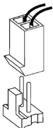
Figure 2: Battery connector
- Disconnect the batteries again to prevent the sounder activating itself. Do not exit installer mode on the alarm panel.
Step 5: Mount the sounder on the wall

Note
A pin serves as an anti-removal wall contact to activate the tamper switch on the inside of the sounder. To fit uneven walls, the length of this pin can be adjusted. To do this, turn the screw, which is in the pin, either in or out.
If the wall tamper contact is still not triggered in the case of extremely uneven walls, you can snap the pin firmly into place by turning it. Tamper detection for the wall is thus deactivated.

Caution
With this installation, the sounder can be torn off the wall without a tamper alarm being triggered. Equally, if the sounder is missing it is no longer possible for an alarm to be signalled. The sounder also loses its certification for security level 2 as a result.
To prevent this, the tamper mechanism can be fixed to the wall, and will break off at the defined predetermined breaking points in the event of a tamper attempt, recognising a tamper alarm.
- Place the sounder on the wall and align it vertically using the integrated spirit level. Mark the three fixing points.

Note
You can also fix the tamper mechanism to the wall.

Note
The appendix also contains a drilling template.
- Drill the holes in the wall to fit the diameter of the screw anchors. Insert the screw anchors supplied, in the holes.
- Insert the screws supplied through the sounder's fixing holes. Turn the screws in the screw anchors. Do not tighten the screws yet.
- Vertically align the sounder again using the spirit level. Now tighten the screws.
Step 6: Switch on sounder

Caution
The sounder should not be activated in the following steps. You should, however, be prepared for the fact that the sounder might nevertheless be activated. Make sure that any loud sounds emitted do not startle you, causing you to fall off the ladder.
- Connect the batteries.
The sounder should switch on in "silent start mode", which is indicated by the fact that the comfort LEDs are permanently on.

Important
Insert the battery cables in the guides provided. Otherwise, the cables may be crushed.
- Put the jumper/connector cover back on, close the lid, tighten the cover fixing screws and close the screws' covers.
Ten seconds after closing the lid, the comfort LEDs will flash alternately to indicate that the sounder is ready. (If you open the lid again, the sounder will activate itself.)
Test the system fully. - Exit installer mode on the alarm panel. The system is now ready.
Functions, jumpers and displays
Installer mode
The sounder's installer mode prevents the sounder and the flashing light from being activated when the cover is opened.
Installer mode is activated when installer mode is called up on the alarm panel and is deactivated when installer mode is exited.
When installer mode is activated, the two comfort LEDs are continuously on for several minutes.
Jumpers and battery connector

Note:
Changes to jumpers are only applied if the sounder's tamper switch is open.
However, if you have closed the tamper switch for testing purposes, a change to the jumpers will not have any effect.
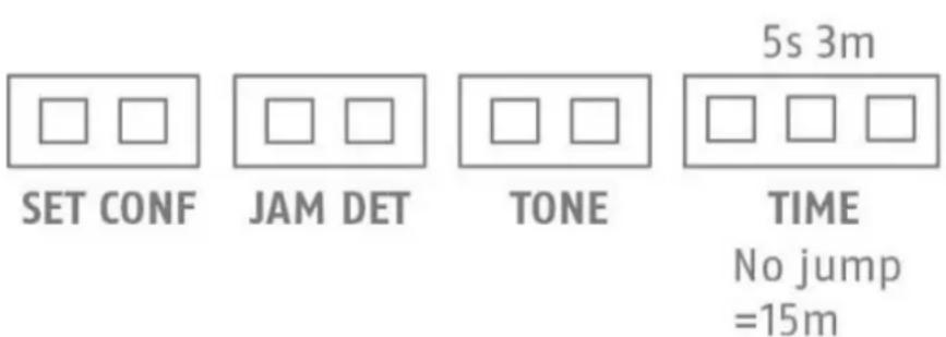
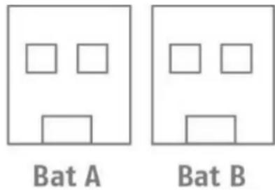
Figure 3: Jumpers and connectors
Key:
Set Conf
Jumper for activating confirmation in the event of the alarm panel being activated/deactivated
Jam Det
Jumper for activating jamming monitoring
Tone
Jumper for selecting the desired normal alarm tone
Time
Jumper for selecting the siren duration
Bat A/Bat B
Battery connectors
Set Conf
Activates or deactivates the flashing light/beep acknowledgement.
If the flashing light is to flash briefly when the system is armed or disarmed, use the alarm panel to enable the "Strobe on Set" or "Strobe on Unset" option in the relevant partition. If the sounder is to beep briefly when the system is armed or disarmed, use the alarm panel to enable the "Beep on Set" or "Beep on Unset" option in the relevant partition.
Installer Mode -> Partitions -> Partition x -> All set / Part set
Jumper connected = flashing light/beep activated
Jumper open = flashing light/beep deactivated
If the jumper is not connected, the sounder ignores the "Strobe on Set", "Strobe on Unset", "Beep on Set" and "Beep on Unset" commands from the alarm panel. The alarm panel sends the commands to all the sounders in the same partition. You can thus only connect the jumpers in certain sounders and not in others.

Note:
Only use the "Strobe on Set", "Strobe on Unset", "Beep on Set" and "Beep on Unset" options if absolutely necessary. If fewer commands need to be processed, this can have a positive impact on the general performance of the system.
Jam Det
If a jumper is set to "Jam Det" (jamming detection, jamming monitoring), the sounder monitors potential attempts to jam the wireless signal to the alarm panel. If signal jamming is detected, the message "Signal jamming" is sent to the alarm panel. The alarm panel can then activate the sounder, depending on the setting.

Note:
The option
Installer Mode -> System -> Security -> Jamming
can be set to "Blocked", "Fault" or "Tamper". If you select "Blocked", signal jamming is not reported. You can find further information on this in the Technical Manual for the alarm panel.
Alarm panels, sounders and special components can monitor signal jamming independently of each other.
Tone
Set the desired normal alarm tone. Two sounders that are placed in direct proximity to one another can thus be distinguished from one another acoustically.
Jumper connected = Normal Alarm Tone 1
Jumper open = Normal Alarm Tone 2
Time
The Tune jumper (off-switch timer) is used to configure the maximum length of time that the acoustic sounder (sounder tone) is active following an alarm. You can choose between five seconds and three minutes.
If you do not connect a jumper, a switch-off time of 15 minutes is set.
Jumper open = 15 minutes
Jumper "3 m" = 3 minutes
Jumper "5 s" = 5 seconds

Note:
The sounder flashes until the alarm is acknowledged on the alarm panel.
BAT A/B
Insert the battery connectors (taking care to observe correct polarity) until the connector is locked in place.

Important
Insert the wires of the battery connector cable into the wire guides provided. Otherwise, the wires may be crushed.
Operation of the comfort LEDs
In normal operation, the comfort LEDs flash alternately if the sounder is connected to the power supply to visually display that the system is operational.
When installer mode is activated on the alarm panel, the two comfort LEDs are continuously on for several minutes. The comfort LEDs are also permanently on during the silent start phase between connection of the batteries and up to ten seconds after closing the cover.

Note:
Software version display
The software version of the sounder is indicated by the comfort LEDs immediately after the power supply is connected.
The red comfort LED indicates the major software version.
The left comfort LED indicates the minor software version.
The red comfort LED indicates the design (2 = wireless sounder).
Example:
Right LED flashes once Left LED flashes eight times Right LED flashes twice Software version "1.8.2"

Note:
- Flashing or non-flashing of the comfort LEDs during normal operation.
Connect the batteries with the cover open.
The software version will be displayed, as described above.
The sounder switches to the silent start-up phase. Both comfort LEDs light up red.
Flip the tampering switch five times, which will turn the flashing on or off.
Their current status is displayed as shown here:
BOTH LEDs on: Comfort LEDs flash during normal operation
ONE LED (right LED) on: Comfort LEDs do not flash during normal operation
The installer mode display and the software display will not be affected by this.
A read-in signal is sent after the version number is displayed. The tampering switch triggers no further transmissions. Only after the silent start-up phase has been brought to an end after the cover has been closed for at least ten seconds will neither red LED be lit anymore.
Operation of the flashing light
The flashing light is activated if the sounder activates itself or the alarm panel sends a command to activate the flashing light.
Fifteen minutes after the sounder is activated, the flashing light flashes more slowly, until the alarm is reset.
With Secvest systems, the options "Strobe on Set" and "Strobe on Unset" can be set in the alarm panel configuration (see Set Conf description).
Error and tamper monitoring
The sounder continually monitors error and tamper states and reports all events to the alarm panel. The following is monitored:
Tamper contact:
The sounder's tamper contact is continually monitored. The sounder activates itself in the event of tampering.
- Battery voltage:
The sounder monitors the battery voltage under load conditions and reports a fault if the remaining battery life is still about one month.
- Signal jamming:
If a jumper is set to "Jam Det" (jamming detection), jamming monitoring is activated and the sounder monitors attempts to jam the wireless signal. (See Jam Det description.) If jamming is detected, the message "Signal jamming" is sent to the alarm panel.
Maintenance

Caution
Before opening the sounder's cover, make sure that the alarm panel is in installer mode. This should prevent the sounder being activated.
You should, however, be prepared for the fact that the sounder might nevertheless be activated. Make sure that any loud sounds emitted do not startle you, causing you to fall off the ladder.
Test, during routine maintenance, that the sounder works properly.
Check the tamper contacts.
Check for signs of seeping water or insects and clean the device as required.
Replace the batteries every two years or if the alarm panel displays the message 'Flat battery in outdoor sounder'. You can find the battery type to be used as a replacement under Technical data.

Note:
Batteries and the device itself must be disposed of in accordance with the WEEE Directive and applicable local and national regulations.

Note:
After removing the old batteries, wait 30 seconds before inserting the new batteries.
How to replace the batteries:
- Put the alarm panel in installer mode.
- Open the covers for the lid-fixing screws (see Fiq. 1), loosen the screws and open the lid.
- Remove the jumper/connector cover (see Fig. 1) by pushing the two fixing tabs outwards and lifting up the cover at the same time.
- Remove the battery connectors from the PCB and remove the batteries.
- Wait 30 seconds, insert the new batteries and connect them to the PCB (see Fig. 2).

Important
Insert the battery cables in the wire guides provided. Otherwise, the cables may be crushed.
- Put the jumper/connector cover back on, close the lid, tighten the cover fixing screws and close the screws' covers.
Test the system.
Warranty

Note
- ABUS products are designed and manufactured with the greatest care and tested according to the applicable regulations.
- The warranty only covers defects caused by material or manufacturing errors at the time of sale. If there are demonstrable material or manufacturing errors, the module will be repaired or replaced at the guarantor's discretion.
- In such cases, the warranty ends when the original warranty period of two years expires. All further claims are expressly rejected.
- ABUS will not be held liable for defects and damage caused by external influences (e.g. transport, use of force, operating errors), inappropriate use, normal wear and tear or failure to observe the instructions in this manual.
- In the event of a warranty claim, the original receipt with the date of purchase and a short written description of the problem must be supplied with the product.
- If you discover a defect on your Wireless Outdoor Sounder which existed at the time of purchase, contact your dealer directly within the first two years following purchase.
Disposal

Dispose of the device in accordance with EU Directive 2012/19/EC - WEEE (Waste Electrical and Electronic Equipment). If you have any questions, please contact the municipal authority responsible for disposal. You can get information on collection points for waste equipment from your local authority, from local waste disposal companies or your dealer, for example.
Declaration of conformity
ABUS Security-Center GmbH & Co. KG hereby declares that the wireless unit type with item number FUSG50101 complies with Directive 2014/53/EU. The full EU declaration of conformity can be found at: www.abus.com Article search FUSG50101/Downloads.
The declaration of conformity can also be obtained from the following address:
Installation instructions and user manual
FR
Chere cliente, cher client,
Installation instructions and user manual
FR
Drug open = Normaal alarm signal 2
Time
Brug open = 15 minutes
Brug "3m" = 3 minuten
Brug "5s" = 5 seconden

Aanwijzing:
Installation instructions and user manual
FR
Installation of sirenen 84
Installation at sirenen
Jumper "3 m" = 3 minutter
Jumper "5 s" = 5 sekunder

Bemerk:
Sirenen blinker, til alarmen kvitteres på alarmcentralen.
BAT A/B
Softwareversion "1.8.2"

Bemerk:
Installation instructions and user manual
FR