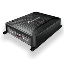
USER MANUAL GM-D8604 PIONEER
BRIDGEABLE FOUR-CHANNEL POWER AMPLIFIER
AMPLIFICATEUR DE PUISSANCE PONTABLE A QUATRE VOIES
AMPLIFICATORE DI POTENZA A QUATTRO CANALI COLLEGABILE A PONTE
PykoBoODCTBO NOIb3OBaTeJIa
Thank you for purchasing this PIONEER product
To ensure proper use, please read through this manual before using this product. It is especially important that you read and observe WARNINGs and CAUTIONs in this manual. Please keep the manual in a safe and accessible place for future reference.

If you want to dispose this product, do not mix it with general household waste. There is a separate collection system for used electronic products in accordance with legislation that requires proper treatment, recovery and recycling.
Private households in the member states of the EU, in Switzerland and Norway may return their used electronic products free of charge to designated collection facilities or to a retailer (if you purchase a similar new one).
For countries not mentioned above, please contact your local authorities for the correct method of disposal.
By doing so you will ensure that your disposed product undergoes the necessary treatment, recovery and recycling and thus prevent potential negative effects on the environment and human health.
Visit our website
Visit us at the following site: http://www.pioneer.co.uk
- Register your product. We will keep the details of your purchase on file to help you refer to this information in the event of an insurance claim such as loss or theft.
We offer the latest information about PIONEER CORPORATION on our website.
If you experience problems
Should this product fail to operate properly, please contact your dealer or nearest authorized Pioneer Service Station.
Before connecting/ installing the amplifier
WARNING
- This unit is for vehicles with a 12 V battery and negative grounding. Before installing in recreational vehicles, trucks or buses, check the battery voltage.
- When installing this unit, make sure to connect the ground wire first. Ensure that the ground wire is properly connected to metal parts of the car's body. The ground wire of the one of this unit must be connected to the car separately with different screws. If the screw for the ground wire loosens or falls out, it could result in fire, generation of smoke or malfunction.
- Be sure to install the fuse to the battery wire.
Always use a fuse of the rating prescribed. The use of an improper fuse could result in overheating and smoke, damage to the product and injury, including burns.
- Check the connections of the power supply and speakers if the fuse of the separately sold battery wire or the amplifier fuse blows. Determine and resolve the cause, then replace the fuse with and identical equivalent.
Always install the amplifier on a flat surface. Do not install the amplifier on a surface that is not flat or on a surface with a protrusion. Doing so could result in malfunction.
Before you start
- When installing the amplifier, do not allow parts such as extra screws to get caught between the amplifier and the automobile. Doing so could cause malfunction.
- Do not allow this unit to come into contact with liquids. Electrical shock could result. Also, damage to this unit, smoke, and overheating could result from contact with liquids. The surfaces of the amplifier and any attached speakers may also heat up and cause minor burns.
- In the event of any abnormality, the power supply to the amplifier is cut off to prevent equipment malfunction. If this occurs, switch the system power off and check the power supply and speaker connections. If you are unable to determine the cause, please contact your dealer.
Always disconnect the negative terminal of the battery beforehand to avoid the risk of electric shock or short circuit during installation.
- Do not attempt to disassemble or modify this unit. Doing so may result in fire, electric shock or other malfunction.

CAUTION
Always keep the volume low enough to hear outside sounds.
- Extended use of the car stereo while the engine is at rest or idling may exhaust the battery.
About the protection function
This product has protection function. When this product detects something abnormal, the following functions will operate to protect the product and speaker output.
- The POWER/PROTECT indicator will turn red and the amplifier will shut down in the situations outlined below.
If the temperature inside the amplifier gets too high.
If a DC voltage is applied to the speaker output terminal.
- The POWER/PROTECT indicator will turn red and the output will be muted in the situations outlined below.
If the speaker output terminal and speaker wire are short-circuited.
What's what
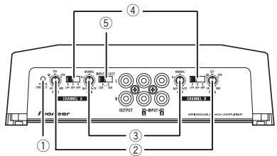
Front side
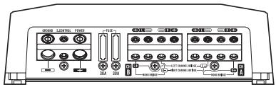
Rear side
To adjust the switch, use a flathead screwdriver if needed.
① POWER/PROTECT indicator
The power indicator lights up to indicate power ON.
- If something is not normal, the indicator turns red.
② FREQ (cut off frequency) control
Cut off frequency selectable from 40Hz to 500Hz if the LPF/HPF select switch is set to LPF or HPF.
③ GAIN (gain) control
Adjusting gain controls CHANNEL A (channel A) and CHANNEL B (channel B) helps align the car stereo output to the Pioneer amplifier. Default setting is the NORMAL position.
If output remains low, even when the car stereo volume is turned up, turn controls to lower level. If distortion occurs when the car stereo volume is turned up, turn these controls to higher level.
- If using only one input plug, set the gain controls for speaker outputs A and B to the same position.
- For use with an RCA equipped car stereo (standard output of 500mV ), set to the NORMAL position. For use with an RCA
equipped Pioneer car stereo, with maximum output of 4 V or more, adjust level to match that of the car stereo output.
- For use with an RCA equipped car stereo with output of 4V , set to the H position.
LPF (low-pass filter)/HPF (high-pass filter) select switch
Switch the settings based on the connected speaker.
- When the Subwoofer is connected: Select LPF. This eliminates high range frequency and outputs low range frequency.
- When the full range speaker is connected:
Select HPF or OFF. HPF eliminates low range frequency and output high range frequency. OFF outputs the entire frequency range.
Select 2CH for two-channel input and 4CH for four-channel input.
Setting gain properly
- Protective function included to prevent malfunction of the unit and/or speakers due to excessive output, improper use or improper connection.
- When outputting high volume sound etc., this function cuts off the output for a few seconds as a normal function, but output is restored when the volume of the head unit is turned down.
- A cut in sound output may indicate improper setting of the gain control. To ensure continuous sound output with the head unit at a high volume, set amplifier gain control to a level appropriate for the preout maximum output level of the head unit, so that volume can remain unchanged and to control excess output.
Setting the unit
- Despite correct volume and gain settings, the unit sound still cuts out periodically. In such cases, please contact the nearest authorized Pioneer Service Station.
Gain control of this unit
Preout level: 2V (Standard: 500mV )
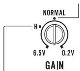
Preout level: 4V
Above illustration shows NORMAL gain setting.
Relationship between amplifier gain and head unit output power
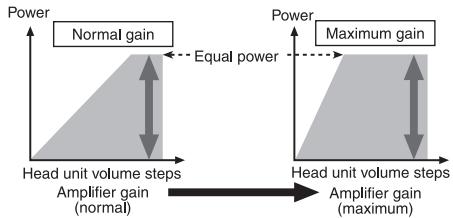
If amplifier gain is raised improperly, this will simply increase distortion, with little increase in power.
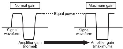
Signal waveform distorted with high output, if you raise the gain of the amplifier the power changes only slightly.
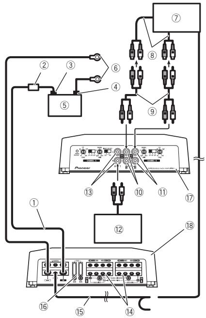
Connection diagram
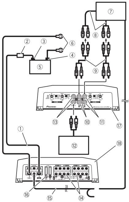
① Battery wire (sold separately)
- The maximum length of the wire between the fuse and the positive terminal of the battery is 30cm
- For the wire size, refer to Connecting the power terminal on page 10. The battery wire, the ground wire and the optional direct ground wire must be same size. After making all other connections at the amplifier, connect the battery wire terminal of the amplifier to the positive terminal of the battery.
② Fuse(80A) (sold separately)
Each amplifier must be separately fused at 80 A.
③ Positive () terminal
Negative (Θ) terminal
⑤ Battery (sold separately)
⑥ Ground wire, Terminal (sold separately)
The ground wires must be same size as the battery wire.
Connect to metal body or chassis.
⑦ Car stereo with RCA output jacks (sold separately)
External output If only one input plug is used, do not connect anything to RCA input jack B.
⑨ Connecting wire with RCA pin plugs (sold separately)
10 RCA input jack A
11 RCA input jack B
⑫ Amplifier with RCA input jacks (sold separately)
13 RCA output jack Outputs the signal input to CH A.
14 Speaker output terminals Please see the following section for speaker connection instructions. Refer to Connections when using the speaker input wire on page 9.
15 System remote control wire (sold separately) Connect male terminal of this wire to the system remote control terminal of the car stereo. The female terminal can be connected to the auto-antenna relay control terminal. If the car stereo lacks a system remote control terminal, connect the male terminal to the power terminal via the ignition switch.
16 Fuse (30A)× 2
17 Front side
18 Rear side
Note
INPUT SELECT (input select) switch must be set.
For details, see Setting the unit on page 4.
Before connecting the amplifier
WARNING
- Secure the wiring with cable clamps or adhesive tape. To protect the wiring, wrap sections in contact with metal parts in adhesive tape.
- Never cut the insulation of the power supply to feed power to other equipment. Current capacity of the wire is limited.

CAUTION
- Never shorten any wires, the protection circuit may malfunction.
- Never wire the speaker negative cable directly to ground.
- Never band together multiple speaker's negative cables.
- If the system remote control wire of the amplifier is connected to the power terminal via the ignition switch (12V DC), the amplifier will remain on with the ignition whether the car stereo is on or off, which may exhaust battery if the engine is at rest or idling.
- Install and route the separately sold battery wire as far as possible from the speaker wires. Install and route the separately sold battery wire, ground wire, speaker wires and the amplifier as far away as possible from the antenna, antenna cable and tuner.
About bridged mode
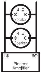
Diagram A - Proper
2Ω Bridged Mode
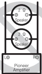
Diagram B - Improper
1Ω Bridged Mode
- Do not install or use this amplifier by wiring speakers rated at 2Ω (or lower) in parallel to achieve a 1Ω (or lower) bridged mode (Diagram B).
Amplifier damage, smoke, and overheating could result from improper bridging. The amplifier surface could also become hot to the touch and minor burns could result.
To properly install or use a bridged mode and achieve a 2Ω load, wire two 4Ω speakers in parallel with Left and Right (Diagram A) or use a single 2Ω speaker.
In addition, refer to the speaker instruction manual for information on the correct connection procedure.
- For any further enquiries, contact your local authorized Pioneer dealer or customer service.
About suitable specification of speaker
Ensure speakers conform to the following standards, otherwise there is a risk of fire, smoke or damage. Speaker impedance is 2Ω to 8Ω or 4Ω to 8Ω for two-channel and other bridge connections.
Subwoofer
| Speaker channel | Power |
| Four-channel output | Nominal input:
Min. 100 W |
| Two-channel output | Nominal input:
Min. 300 W |
| Three-channel
output | Speaker output | Nominal input:
Min. 100 W |
| A |
| Speaker output | Nominal input:
Min. 300 W |
| B |
Other than subwoofer
| Speaker channel | Power |
| Four-channel output | Max. input:
Min. 200 W |
| Two-channel output | Max. input:
Min. 600 W |
| Three-channel output | Speaker output A | Max. input:
Min. 200 W |
| Speaker output B | Max. input:
Min. 600 W |

Connecting the speakers
The speaker output mode can be four-channel, three-channel (stereo and mono) or two-channel (stereo or mono). Connect the speaker leads based on the mode and the figures shown below.
Four-channel output
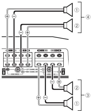
① Left
(2) Right
③ Speaker output A
④ Speaker output B
Two-channel output (Stereo)
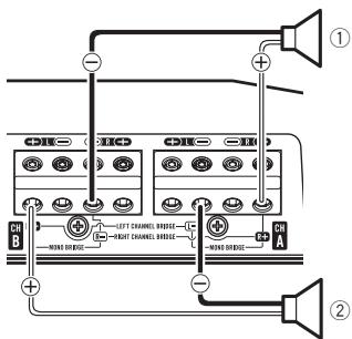
① Speaker output (Right)
② Speaker output (Left)
Two-channel output (Mono)
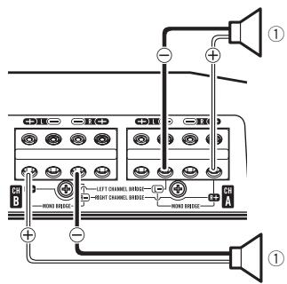
① Speaker output (Mono)
Three-channel output
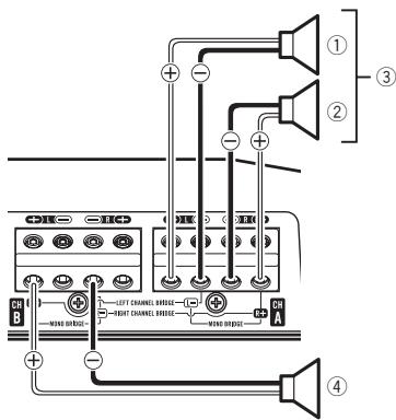
① Left
② Right
③ Speaker output A
④ Speaker output B (Mono)
Connect the car stereo RCA output jack and the RCA input jack of the amplifier.
- The RCA output jack of this unit outputs the signal that comes from The RCA input jack A.
Four-channel / Three-channel output
- Slide INPUT SELECT (input select) switch to 4CH position.
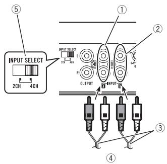
① RCA input jack A
② RCA input jack B
③ Connecting wires with RCA plugs (sold separately)
④ From car stereo (RCA output) If only one input plug is used, e.g. when the car stereo has only one output (RCA output), connect the plug to RCA input jack A rather than B.
⑤ INPUT SELECT (input select) switch (4CH position)
Two-channel output (Stereo) / (Mono)
- Slide INPUT SELECT (input select) switch to 2CH position.
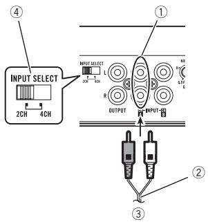
① RCA input jack A For two-channel output, connect the RCA plugs to the RCA input jack A.
② Connecting wire with RCA pin plugs (sold separately)
③ From car stereo (RCA output)
④ INPUT SELECT (input select) switch (2CH position)
Connect the car stereo speaker output wires to the amplifier using the supplied speaker input wire with RCA pin cord.
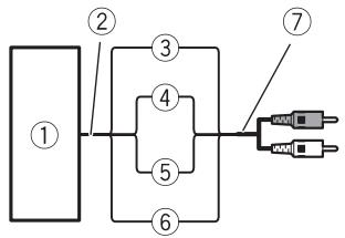
① Car Stereo
② Speaker output
③ Red: Right ⊕
④ Black: Right
⑤ Black: Left
⑥ White: Left
⑦ Speaker input wire with RCA pin cord To the RCA input jack of this unit
Notes
- If speaker wires with an RCA pin cord from a headunit are connected to this amplifier, the amplifier will automatically turn on when the headunit is turned on. When the headunit is turned off, the amplifier turns off automatically. This function may not work with some headunits. In such cases, please use a system remote control wire (sold separately). If multiple amplifiers are to be connected together synchronously, connect the head unit and all amplifiers via the system remote control wire.
- Connect the system remote control wire when you wish to only turn on the car stereo, not the amplifier.
Connecting the units
- This amplifier automatically selects an input signal mode between the RCA level and the speaker level by detecting an input signal.
Solderless terminal connections
- Since the wire will become loose over time, it must be periodically inspected and tightened as necessary.
- Do not solder or bind the ends of the twisted wires.
- Fasten while making sure to not to clamp the insulating sheath of the wire.
- Use the supplied hexagonal wrench to tighten and loosen the terminal screw of the amplifier and use it to securely fasten the wire. Be careful to avoid excessive tightening of this screw, which may damage the wire.
Connecting the power terminal

WARNING
If the battery wire is not securely fixed to the terminal using the terminal screws, there is a risk of overheating, malfunction and injury, including minor burns.
Always use the recommended battery and ground wire, which is sold separately. Connect the battery wire directly to the car battery positive () terminal and the ground wire to the car body.
- Recommended wires size (AWG: American Wire Gauge) is as follows. The battery wire, the ground wire and the optional direct ground wire must be same size.
- Use a wire of 8AWG to 16AWG wire for the speaker wire.
Battery wire and ground wire size
| Wire length | Wire size |
| less than 4.5 m | 8 AWG |
| less than 7.2 m | 6 AWG |
| less than 11.4 m | 4 AWG |
1 Route battery wire from engine compartment to the vehicle interior.
- When drilling a cable pass-hole into the vehicle body and routing a battery wire thorough it, take care not to short-circuit the wire damaging it by the cut edges or burrs of the hole.
After completing all other amplifier connections, finally connect the battery wire terminal of the amplifier to the positive () battery terminal.
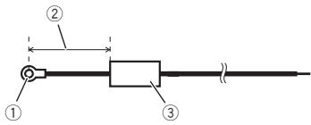
① Positive () terminal
② Battery wire (sold separately) The maximum length of the wire between the fuse and the positive terminal of the battery is 30cm
③ Fuse (80A) (sold separately) Each amplifier must be separately fused at 80 A.
Connecting the units
2 Use wire cutters or a utility knife to strip the end of the battery wire, ground wire and system remote control wire to expose about 10mm of the end of each of the wires, and then twist the exposed ends of the wires.
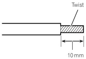
3 Connect the wires to the terminal.
Fix the wires securely with the terminal screws.
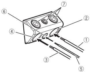
① Battery wire
② Power terminal
③ Ground wire
④ GND terminal
⑤ System remote control wire
⑥ System remote control terminal
⑦ Terminal screws
Connecting the speaker output terminals
1 Use wire cutters or a utility knife to strip the end of the speaker wires to expose about 10mm of wire and then twist the wire.
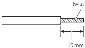
2 Connect the speaker wires to the speaker output terminals.
Fix the wires securely with the terminal screws.
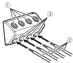
① Terminal screws
② Speaker wires
③ Speaker output terminals
Before installing the amplifier

WARNING
- To ensure proper installation, use the supplied parts in the manner specified. If any parts other than those supplied are used, they may damage internal parts of the amplifier, or become loose causing the amplifier to shut down.
- Do not install in:
Places where it could injure the driver or passengers if the vehicle stops suddenly.
Places where it may interfere with the driver, such as on the floor in front of the driver's seat.
- Install tapping screws in such a way that the screw tip does not touch any wire. This is important to prevent wires from being cut by vibration of the car, which can result in fire.
- Make sure that wires do not get caught in the sliding mechanism of the seats or touch the legs of a person in the vehicle as short-circuit may result.
- When drilling to install the amplifier, always confirm no parts are behind the panel and protect all cables and important equipment (e.g. fuel/brake lines, wiring) from damage.

CAUTION
-
To ensure proper heat dissipation of the amplifier, ensure the following during installation:
-
Allow adequate space above the amplifier for proper ventilation.
-
Do not cover the amplifier with a floor mat or carpet.
-
Place all cables away from hot places, such as near the heater outlet.
- The optimal installation location differs depending on the car model. Secure the amplifier at a sufficiently rigid location.
- Check all connections and systems before final installation.
After installing the amplifier, confirm that the spare tire, jack and tools can be easily removed.
Example of installation on the floor mat or chassis
1 Place the amplifier in the desired installation location.
Insert the supplied tapping screws (4 mm × 18 mm) into the screw holes and push on the screws with a screwdriver so they make an imprint where the installation holes are to be located.
2 Drill 2.5mm diameter holes at the imprints either on the carpet or directly on the chassis.
3 Install the amplifier with the use of supplied tapping screws (4mm× 18mm)
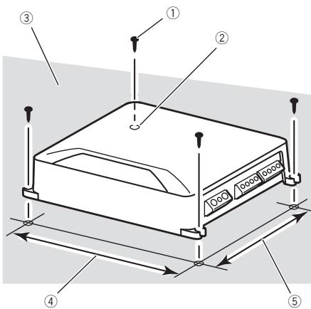
① Tapping-screws (4mm × 18mm)
② Drill a 2.5 mm diameter hole
③ Floor mat or chassis
④ Hole-to-hole distance: 257 mm
⑤ Hole-to-hole distance: 181 mm
Specifications
Power source 14.4 V DC (10.8 V to 15.1 V allowable)
Grounding system Negative type
Current consumption 33.5 A (at continuous power, 4Ω
Average current drawn 3.1 A (4 Ω for four channels)
4.4 A (4Ω for two channels, BRIDGE)
4.4 A (2Ω for four channels)
Fuse 30 A x 2
Dimensions (W× H× D) ...265 mm x 60 mm x 200 mm
Weight 2.6 kg (Leads for wiring not included)
Maximum power output ....200W × 4 4Ω) / 600W × 2
(4Ω) BRIDGE / TOTAL
1200W(300W×4)
Continuous power output ... 100W× 4 (at 14.4V,4Ω
20 Hz to 20 kHz, ≤ 1% THD)
150W×4 (at 14.4V,2Ω)
1 kHz, ≤ 1% THD)
125 W × 4 (at 14.4 V, 1 Ω)
1 kHz, ≤ 1% THD)
300W× 2 (at 14.4V,4Ω
BRIDGE, 1 kHz, ≤ 1% THD)
250 W × 2 (at 14.4 V, 2 Ω
BRIDGE, 1 kHz, ≤ 1% THD)
Load impedance 4Ω (1Ω to 8Ω allowable)
Frequency response 10 Hz to 50 kHz (+0 dB, -3 dB)
Signal-to-noise ratio 95 dB (IEC-A network)
Distortion . 0.05% (10 W, 1 kHz)
Low pass filter:
Cut off frequency 40 Hz to 500 Hz
Cut off slope .12 dB/oct
High pass filter:
Cut off frequency 40 Hz to 500 Hz
Cut off slope -12 dB/oct
Gain control:
RCA 200 mV to 6.5 V
Speaker 0.8 V to 16 V
Maximum input level / impedance:
RCA 6.5V/25kΩ
Speaker 16 V/12 kΩ
Notes
- Specifications and the design are subject to modifications without notice.
- The average current drawn is nearly the maximum current drawn by this unit when an audio signal is input. Use this value when
working out total current drawn by multiple power amplifiers.
Avant de commencer
③ Commande GAIN (gain)
20 Hz a 20 kHz, ≤ 1% THD)
150W× 4 a14,4V,2Ω
1 kHz, ≤ 1% THD)
125W× 4 a 14,4V,1Ω ,
1 kHz, ≤ 1% THD)
300W× 2 a14,4V,4Ω
BRIDGE, 1 kHz, ≤ 1% THD)
250W×2 (a 14,4V, 2Ω
BRIDGE, 1 kHz, ≤ 1% THD)
Distorsione 0,05% (10 W, 1 kHz)
Filtro passa basso:
④ Selectieschakelaar LPF/HPF (low pass filter/high pass filter)
OTHOSeHHe KO3ΦΦnIeHtA yCnJIeHnY CnJIInTeJI N BbIXoJHoM MoUHOCTH OCHOBHOrO yCTpoIcTBA

PnUype3MepHOM NOBbIeHIN KO3OΦpHcneH-Ta yCnJIeHnpe3KO YBeJIuHbAIOTCNCKaKeHnA, a MOUHOCTb NOBbIaETCaHe3HaHTeJIbHO.
ΦopMa CnΓHana Ha BbIXOe npn BbICOKOM ypOBHe rPOMKoCTn, C03daHHOM C nOMOuIbO peRyJIaTOPa Ko3ΦΦnUeHTa YcHJIeHNr YcNlNTeJIa
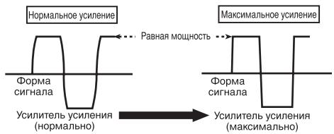
NcKaJehHnaΦopMa CnHaIa Pnp BbICOKom yPoBHe rPOMKoCTn. Pnp NObblueHm K03Φ-ΦnUeHtA yCnJIeHnA yCnJIInTeIa MOuHOCTb n3MeHReTc Hc3HaHTeJIbHo.
Cxema nodkloucheHna
CpeHHee 3NaueHne ToKa ...3,1A (4ΩДЯ YeTbIpex KaHaNoB)
4,4 A (4ΩДЯДБУХΚΑнАЛов, MOCTOBOE BКЛHО-УЕНЕ)
4,4A (2ΩДЯЧтырека-нанов)
Плавский п体现在хантел b 30A×2
Pa3Mepbl (U × B × Γ) 265MM × 60MM × 200MM
Bec 2,6 Kr (6e3 yyeTa npoBO- IOB)
Makcimambna BbIXoHna MoUHOCTb 200Bt × 4(4Ω)/600Bt× 2(4Ω)MOCTOBE/NOJI- HOE1200Bt(300Bt × 4)
HOMHaJIbHaJIyBbIXoDHaMoOIOCTb 100T×4(pnp14,4B,4Ω,OT20ΓUdo20KΓU,≤1% cymMapHoro3naeHnKa- 3ΦΦuIeHTaHeHHeHbIx nckaxKeH)
150Bt × 4 (pnp14,4B,2Ω,1KU,≤1%cymmapHOrO3haeHnna Ko3dunmEHTaHeHHneHbIX NCKaKeHEN)
125Bt × 4 (pnp14,4B,1Ω,1KtU, ≤ 1% cymmaHrO3haeHnKa03ΦnIeHNTaHeHHeHbIX NcKaXeHnI)
300Bt×2 (npn 14,4B,4Ω MOCTOBOE,1KΓι,≤1% cymmapHOrO 3NaueHnKaΦφπηεHα ένημηκθινιχινικακεHη)
250 Bt × 2 (npn 14,4 B, 2Ω
Visit www.pioneer.co.uk (or www.pioneer.eu) to register your product.
UmmopTeP OOO "IIOHEP PYC"
125040, Pocnra, r. MockBa, yn. PpaBbl, d.26
Ten.: +7(495) 956-89-01
PIONEER ELECTRONICS (USA) INC.
P.O. Box 1540, Long Beach, California 90801-1540, U.S.A.
TEL: (800) 421-1404
PIONEER EUROPE NV
Haven 1087, Keetberglaan 1, B-9120 Melsele, Belgium/Belgique
TEL: (0) 3/570.05.11
PIONEER ELECTRONICS ASIACENTRE PTE. LTD.
253 Alexandra Road, #04-01, Singapore 159936
TEL: 65-6472-7555
PIONEER ELECTRONICS AUSTRALIA PTY. LTD.
5 Arco Lane, Heatherton, Victoria, 3202 Australia
TEL: (03) 9586-6300
PIONEER ELECTRONICS OF CANADA, INC.
340 Ferrier Street, Unit 2, Markham, Ontario L3R 2Z5, Canada
TEL: 1-877-283-5901
TEL: 905-479-4411
PIONEER ELECTRONICS DE MEXICO, S.A. de C.V.
Blvd.Manuel Avila Camacho 138 10 piso
Col.Lomas de Chapultepec, Mexico, D.F. 11000
TEL: 55-9178-4270
先鋒股份有限公司
台北市內湖區瑞光路407號8樓
電話:886- (0)2- 2657-3588
先鋅電子(香港)有限公司
香港九龍長沙灣道909號5樓
電話:852-2848-6488
© 2012 PIONEER CORPORATION.
All rights reserved.
© 2012 PIONEER CORPORATION.