GM-6500F - Car amplifier PIONEER - Free user manual and instructions
Find the device manual for free GM-6500F PIONEER in PDF.
User questions about GM-6500F PIONEER
0 question about this device. Answer the ones you know or ask your own.
Ask a new question about this device
Download the instructions for your Car amplifier in PDF format for free! Find your manual GM-6500F - PIONEER and take your electronic device back in hand. On this page are published all the documents necessary for the use of your device. GM-6500F by PIONEER.
USER MANUAL GM-6500F PIONEER
If you want to dispose this product, do not mix it with general household waste. There is a separate collection system for used electronic products in accordance with legislation that requires proper treatment, recovery and recycling.
Private households in the member states of the EU, in Switzerland and Norway may return their used electronic products free of charge to designated collection facilities or to a retailer (if you purchase a similar new one).
For countries not mentioned above, please contact your local authorities for the correct method of disposal.
By doing so you will ensure that your disposed product undergoes the necessary treatment, recovery and recycling and thus prevent potential negative effects on the environment and human health.
Thank you for purchasing this PIONEER product.
To ensure proper use, please read through this manual before using this product. It is especially important that you read and observe
WARNINGs and CAUTIONs in this manual.
Please keep the manual in a safe and accessible place for future reference.
Visit our website
Visit us at the following site: http://www.pioneer.co.uk
- Register your product. We will keep the details of your purchase on file to help you refer to this information in the event of an insurance claim such as loss or theft.
We offer the latest information about PIONEER CORPORATION on our website.
In case of trouble
Should this product fail to operate properly, please contact your dealer or nearest authorized Pioneer Service Station.
Before connecting/ installing the amplifier
WARNING
- The use of a special red battery and ground wire RD-223, available separately, is recommended. Connect the battery wire directly to the car battery positive terminal and the ground wire to the car body.
- This unit is for vehicles with a 12 V battery and negative grounding. Before installing in recreational vehicles, trucks or buses, check the battery voltage.
Always use a fuse of the rating prescribed. The use of an improper fuse could result in overheating and smoke, damage to the product and injury, including burns. - Check the connections of the power supply and speakers if the fuse of the separately sold battery wire or the amplifier fuse blows. Determine and resolve the cause, then replace the fuse with and identical equivalent.
- Do not allow this unit to come into contact with liquids. Electrical shock could result. Also, damage to this unit, smoke, and overheating could result from contact with liquids. The surfaces of the amplifier and any attached speakers may also heat up and cause minor burns.
Before you start
- In the event of any abnormality, the power supply to the amplifier is cut off to prevent equipment malfunction. If this occurs, switch the system power off and check the power supply and speaker connections. If you are unable to determine the cause, please contact your dealer.
Always disconnect the negative terminal of the battery beforehand to avoid the risk of electric shock or short circuit during installation.

CAUTION
Always keep the volume low enough to hear outside sounds.
- Extended use of the car stereo while the engine is at rest or idling may exhaust the battery.
About the Protection function
The Protection function will operate in the conditions outlined below. If the Protection function is turned on, the power indicator will turn off, and the amplifier will shut down.
- If the speaker output terminal and speaker wire is short-circuited.
If the temperature inside the amplifier gets too high.
If a DC voltage is applied to the speaker output terminal.
What's what
Front side
Rear side
To adjust the switch, use a flathead screwdriver if needed.
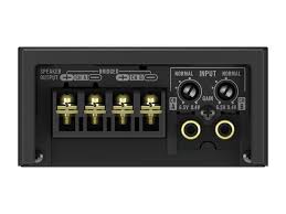
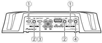
① LPF (low-pass filter)/HPF (high-pass filter) select switch
Switch the settings based on the connected speaker.
- When the Subwoofer is connected: Select LPF. This eliminates high range frequency and outputs low range frequency.
- When the full range speaker is connected:
Select HPF or OFF. HPF eliminates low range frequency and output high range frequency. OFF outputs the entire frequency range.
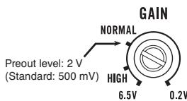
② GAIN (gain) control
Adjusting gain controls CHANNEL A (channel A) and CHANNEL B (channel B) helps align the car stereo output to the Pioneer amplifier. Default setting is the NORMAL position.
If output remains low, even when the car stereo volume is turned up, turn controls to lower level. If distortion occurs when the car stereo volume is turned up, turn these controls to higher level.
-
If using only one input plug, set the gain controls for speaker outputs A and B to the same position.
-
For use with an RCA equipped car stereo (standard output of 500mV ), set to the NORMAL position. For use with an RCA equipped Pioneer car stereo, with max. output of 4V or more, adjust level to match that of the car stereo output.
③ INPUT SELECT (input select) switch
Select 2CH for two-channel input and 4CH for four-channel input.
- You can select input select only for connections when using the RCA input jack. For connections when using the speaker input wire, 4CH will be used automatically no matter which switch setting is selected.
④ FREQ (cut off frequency) control
Cut off frequency selectable from 40Hz to 500Hz if the LPF/HPF select switch is set to LPF or HPF.
- You can select cut off frequency only for CHANNEL B.
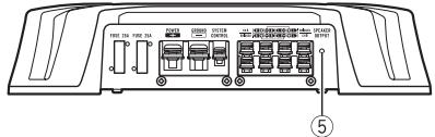
⑤ Power indicator
The power indicator lights up to indicate power ON.
Setting gain properly
- Protective function included to prevent malfunction of the unit and/or speakers due to excessive output, improper use or improper connection.
- When outputting high volume sound etc., this function cuts off the output for a few seconds as a normal function, but output is restored when the volume of the head unit is turned down.
- A cut in sound output may indicate improper setting of the gain control. To ensure continuous sound output with the head unit at a high volume, set amplifier gain control to a level appropriate for the preout maximum output level of the head unit, so that volume can remain unchanged and to control excess output.
Setting the unit
- Despite correct volume and gain settings, the unit sound still cuts out periodically. In such cases, please contact the nearest authorized Pioneer Service Station.
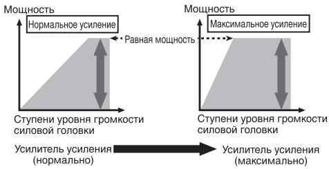
Gain control of this unit
Above illustration shows NORMAL gain setting.
Relationship between amplifier gain and head unit output power
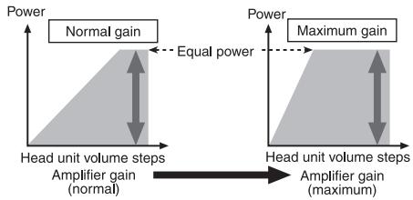
If amplifier gain is raised improperly, this will simply increase distortion, with little increase in power.
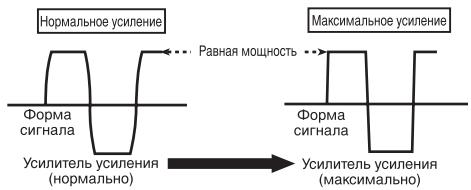
Signal waveform when outputting at high volume using amplifier gain control
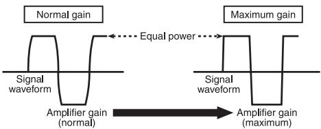
Signal waveform distorted with high output, if you raise the gain of the amplifier the power changes only slightly.
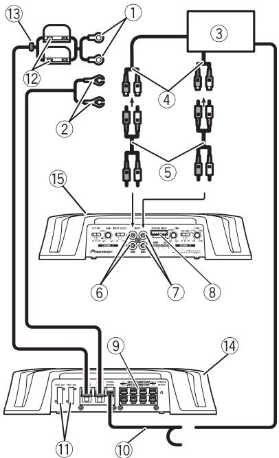
Connection diagram

① Special red battery wire RD-223 (sold separately)
After completing all other amplifier connections, finally connect the battery wire terminal of the amplifier to the positive () battery terminal.
② Ground wire (Black)
RD-223 (sold separately)
Connect to metal body or chassis.
③ Car stereo with RCA output jacks (sold separately)
(4) External output
If only one input plug is used, do not connect anything to RCA input jack B.
⑤ Connecting wire with RCA pin plugs (sold separately)
⑥ RCA input jack A
⑦ RCA input jack B
⑧ Speaker input terminal (use a connector included)
Please see the following section for speaker connection instructions. Refer to Connections when using the speaker input wire on page 9.
⑨ Speaker output terminals
Please see the following section for speaker connection instructions. Refer to Connections when using the speaker input wire on page 9.
10 System remote control wire (sold separately) Connect male terminal of this wire to the system remote control terminal of the car stereo. The female terminal can be connected to the auto-antenna relay control terminal. If the car stereo lacks a system remote control terminal, connect the male terminal to the power terminal via the ignition switch.
1 Fuse (25A)× 2
⑫ Fuse (30A)× 2
⑬ Grommet
14 Rear side
15 Front side
Note
INPUT SELECT (input select) switch must be set.
For details, see Setting the unit on page 4.
Before connecting the amplifier

WARNING
- Secure the wiring with cable clamps or adhesive tape. To protect the wiring, wrap sections in contact with metal parts in adhesive tape.
- Never cut the insulation of the power supply to feed power to other equipment. Current capacity of the wire is limited.

CAUTION
- Never shorten any wires, the protection circuit may malfunction.
- Never ground speaker wire directly or band together multiple speakers' negative (Θ) lead wires.
Connecting the units
- If the system remote control wire of the amplifier is connected to the power terminal via the ignition switch (12 V DC), the amplifier will remain on with the ignition whether the car stereo is on or off, which may exhaust battery if the engine is at rest or idling.
Install and route the separately sold battery wire as far as possible from the speaker wires. Install and route the separately sold battery wire, ground wire, speaker wires and the amplifier as far away as possible from the antenna, antenna cable and tuner.
About bridged mode
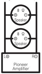
Diagram A - Proper
4Ω Bridged Mode
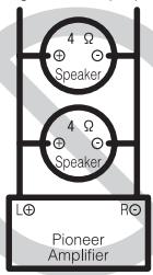
Diagram B - Improper
2Ω Bridged Mode
Speaker impedance is max. 4 please carefully check. Improper connection to the amplifier may result in malfunction or personal injury due to burns from overheating.
For bridged mode for a two-channel amplifier, with a 4 load, either wire two 8 speakers in parallel, Left and Right (Diagram A) or use a single 4 speaker. For other amplifiers, please follow the speaker output connection diagram for bridging shown on rear: two 8 speakers in parallel for a 4 load or a single 4 speaker per channel.
For any further enquiries, contact your local authorized Pioneer dealer or customer service.
About suitable specification of speaker
Ensure speakers conform to the following standards, otherwise there is a risk of fire, smoke or damage. Speaker impedance is 2 to 8 or 4 to 8 for two-channel and other bridge connections.
Subwoofer
| Speaker channel | Power |
| Four-channel output | Nominal input: Min. 60 W |
| Two-channel output | Nominal input: Min. 180 W |
| Three-channel Speaker output A | Nominal input: Min. 60 W |
| Three-channel Speaker output B | Nominal input: Min. 180 W |
Other than subwoofer
| Speaker channel | Power |
| Four-channel output | Max. input: Min. 120 W |
| Two-channel output | Max. input: Min. 360 W |
| Three-channel | Max. input: Min. 120 W |
| Speaker output A | |
| Three-channel | Max. input: |
| Speaker output B | Min. 360 W |

Connecting the speakers
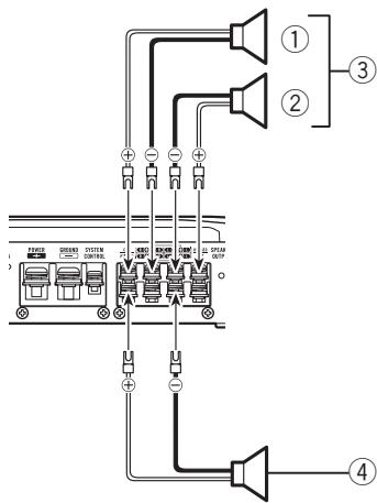
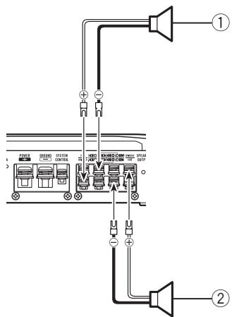
The speaker output mode can be four-channel, three-channel (stereo and mono) or two-channel (stereo or mono). Connect the speaker leads based on the mode and the figures shown below.
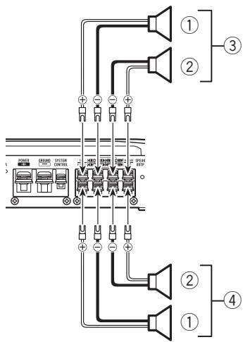
Four-channel output
① Right
② Left
③ Speaker out A
④ Speaker out B
Three-channel output
① Right
② Left
③ Speaker out A
④ Speaker out B (Mono)
Two-channel output (Stereo)
① Speaker (Right)
② Speaker (Left)

Two-channel output (Mono)
① Speaker (Mono)
Connections when using the RCA input jack
Connect the car stereo RCA output jack and the RCA input jack of the amplifier.
Four-channel / Three-channel output
- Slide INPUT SELECT (input select) switch to 4CH position.
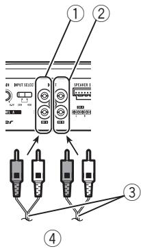
① RCA input jack A
② RCA input jack B
③ Connecting wires with RCA plugs (sold separately)
4 From car stereo (RCA output) If only one input plug is used, e.g. when the car stereo has only one output (RCA output), connect the plug to RCA input jack A rather than B.
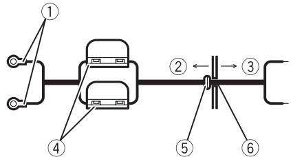
Two-channel output (Stereo) / (Mono)
- Slide INPUT SELECT (input select) switch to 2CH position.
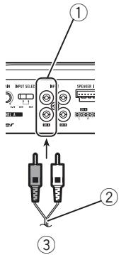
① RCA input jack A
For two-channel output, connect the RCA plugs to the RCA input jack A.
② Connecting wire with RCA pin plugs (sold separately)
③ From car stereo (RCA output)
Connections when using the speaker input wire
Connect the car stereo speaker output wires to the amplifier using the supplied speaker input wire.
- Do not connect both the RCA input and the speaker input at the same time.
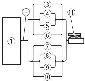
① Car Stereo
② Speaker output
③ White/black: CH A, Left
④ White: CH A, Left ⊕
⑤ Gray/black: CH A, Right Θ
⑥ Gray: CH A, Right ⊕
⑦ Green/black: CH B, Left
Green:CHB,Left
⑨ Violet/black:CHB,Right
Violet: CH B, Right
⑪ Speaker input connector To speaker input terminal of this unit.
Connecting the power terminal
The use of a special red battery and ground wire RD-223, available separately, is recommended. Connect the battery wire directly to the car battery positive terminal and the ground wire to the car body.
Connecting the units

WARNING
If the battery wire is not securely fixed to the terminal using the terminal screws, there is a risk of overheating, malfunction and injury, including minor burns.
1 Route battery wire from engine compartment to the vehicle interior.
After completing all other amplifier connections, finally connect the battery wire terminal of the amplifier to the positive () battery terminal.
① Positive () terminal
② Engine compartment
③ Vehicle interior
④ Fuse(30A)×2
⑤ Insert the O-ring rubber grommet into the vehicle body.
⑥ Drill a 14 mm hole into the vehicle body.
2 Twist the battery wire, ground wire and system remote control wire.

3 Attach lugs to wire ends.
Use pliers, etc., to crimp lugs to wires.
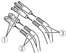
① Lug (sold separately)
② Battery wire
③ Ground wire
4 Connect the wires to the terminal. Fix the wires securely with the terminal screws.
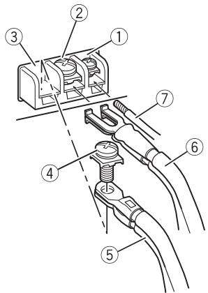
① System remote control terminal
② Ground terminal
③ Power terminal
(4) Terminal screws
⑤ Battery wire
⑥ Ground wire
⑦ System remote control wire
Connecting the speaker output terminals
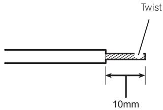
1 Use wire cutters or a utility knife to strip the end of the speaker wires to expose about 10mm of wire and then twist the wire.
2 Attach lugs to wire ends.
Use pliers, etc., to crimp lugs to wires.
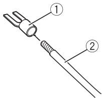
① Lug (sold separately)
② Speaker wire
3 Connect the speaker wires to the speaker output terminals.
Fix the speaker wires securely with the terminal screws.
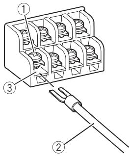
① Terminal screws
② Speaker wires
③ Speaker output terminals
Before installing the amplifier

WARNING
- To ensure proper installation, use the supplied parts in the manner specified. If any parts other than those supplied are used, they may damage internal parts of the amplifier, or become loose causing the amplifier to shut down.
- Do not install in:
Places where it could injure the driver or passengers if the vehicle stops suddenly.
Places where it may interfere with the driver, such as on the floor in front of the driver's seat.
- Install tapping screws in such a way that the screw tip does not touch any wire. This is important to prevent wires from being cut by vibration of the car, which can result in fire.
- Make sure that wires do not get caught in the sliding mechanism of the seats or touch the legs of a person in the vehicle as short-circuit may result.
- When drilling to install the amplifier, always confirm no parts are behind the panel and protect all cables and important equipment (e.g. fuel/brake lines, wiring) from damage.

CAUTION
-
To ensure proper heat dissipation of the amplifier, ensure the following during installation:
-
Allow adequate space above the amplifier for proper ventilation.
-
Do not cover the amplifier with a floor mat or carpet.
-
Protection function may activate to protect the amplifier against overheating due to installation in locations where sufficient heat cannot be dissipated, continuous use under high-volume conditions, etc. In such cases, the amplifier shuts down until it has cooled to a certain designated temperature.
-
Avoid routing wires through hot areas, such as near the heater outlet. Heat may damage the insulation, resulting in a short-circuit through the vehicle body.
-
The optimal installation location differs depending on the car model. Secure the amplifier at a sufficiently rigid location.
- Firstly make temporary connections and check to ensure the amplifier and system operate properly.
After installing the amplifier, confirm that the spare tire, jack and tools can be easily removed.
Example of installation on the floor mat or chassis
1 Place the amplifier in the desired installation location.
Insert the supplied tapping screws (4 mm × 18 mm) into the screw holes and push on the screws with a screwdriver so they make an imprint where the installation holes are to be located.
2 Drill 2.5mm diameter holes at the imprints either on the carpet or directly on the chassis.
3 Install the amplifier with the use of supplied tapping screws (4mm× 18mm)
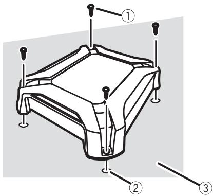
① Tapping-screws (4mm × 18mm)
② Drill a 2.5 ~mm diameter hole
③ Floor mat or chassis
Additional information
Specifications
Power source 14.4 V DC (10.8 V to 15.1 V
allowable)
Grounding system Negative type
Current consumption 32 A (at continuous power,
4Ω)
Average current drawn 9 A (4 Ω for four channels)
15 A (4 Ω for two channels)
Fuse 25A×2
Dimensions (W× H× D) ...289 mm × 62 mm × 349
mm
Weight 3.3 kg (Leads for wiring not
included)
Maximum power output ....760 W (190 W x 4)
Continuous power output ... 60W× 4 (at 14.4V,4
20 Hz to 20 kHz ≤ 1% THD
+N)
180W× 2 (at 14.4V,4
BRIDGE 1 kHz, ≤ 1% THD
+N)
85W× 4 (at 14.4V,2
1 kHz, ≤ 1% THD+N)
Load impedance 4Ω (2 Ω to 8Ω allowable)
Frequency response 10 Hz to 70 kHz (+0 dB, -
3dB)
Signal-to-noise ratio 98 dB (IEC-A network)
Distortion . 0.05% (10 W, 1 kHz)
Low pass filter:
(Ach)
Cut off frequency 80 Hz
Cut off slope .12 dB/0ct
(Bch)
Cut off frequency 40 Hz to 500 Hz
Cut off slope . 12 dB/oct
High pass filter:
(Ach)
Cut off frequency 80 Hz
Cut off slope . 12 dB/oct
(Bch)
Cut off frequency 40 Hz to 500 Hz
Cut off slope -12 dB/oc
Gain control:
RCA 200 mV to 6.5 V
Speaker 0.8 V to 26 V
Maximum input level / impedance:
RCA 6.5 V/22 kΩ
Speaker 26V/22kΩ
Notes
- Specifications and the design are subject to modifications without notice.
- The average current drawn is nearly the maximum current drawn by this unit when an
audio signal is input. Use this value when working out total current drawn by multiple power amplifiers.

② Commande GAIN (gain)
PONTÉ 1 kHz, ≤ 1% THD
+N)
85W× 4 (a 14,4V,2
1 kHz, ≤ 1% THD+N)
20 Hz a 20 kHz, ≤ 1% THD
+N)
180W× 2 a 14,4V,4
BRIDGE 1 kHz, ≤ 1% THD
+N)
85W× 4 a14,4V,2Ω
1 kHz, ≤ 1% THD+N)
Distorsione 0,05% (10 W, 1 kHz)
Filtro passa basso:
(Canale A)
① Selectieschakelaar LPF/HPF (low pass filter/high pass filter)
BRUG 1 kHz, ≤ 1% THD+N)
OTHOSeHHe Ko3ΦΦnIeHtA yCnJIeHnY CnJIInTeJI N BbIXOJHoM MoUHOCTH OCHOBHOrO yCTpoIcTBA
PnUype3MepHOM NOBbIeHIN KO3OΦpHcneH-Ta yCnJIeHnpe3KO YBeJIuHbAIOTCNCKaKeHnA, a MOUHOCTb NOBbIaETCaHe3HaHTeJIbHO.
ΦopMa CnΓHana Ha BbIXOe npn BbICOKOM ypOBHe rPOMKoCTn, C03daHHOM C nOMOuIbO peRyJIaTOPa Ko3ΦΦnUeHTa ycHJIeHNy ycNlNTeJIa
NcKaJehHnaФopMa CnHaHpa Prn BbICOKOM yPoBHe rPOMKoCTn. PnIOBbIeHmN KO3Φ-ΦnIeHtA yCnJIeHnA yCnJIInTeTЯ MOUHOCTb N3MeHReTc Hc3HaHTeJIbHo.
Cxema nodkloucheHna
① CneuaNbHbI KpaChbI npOBd IJa NOdkJIO-ueHnKaKKymyTOpY
RD-223 (npoaeTcO tDeIbHo)
Iocne IOKHueHn BCex npoBOOB ycINITeI NocJeHNM IOKJIouHTe pOBOD, NyuIOn OT KJEMMbI ycINITeJI K
NIOJXHTeHbHO () KJIeMMe aKkymyTota.
② ПобOD 3a3eMJIeHЯ (YeHbI)
RD-223 (npno6petaetcOtDneBHO)
ПодсоевинтЕ К Металл用电�ьоврхон CTи ПИншаци.
③ ABTomO6nIbHaaydInocStema C BbIXoHbIMn Ihe3dAmn IJyIPOkJIuOeHnKa6eIra RCA (pnpo6peTaetcOtDeIbHo)
④ BHeuHbYbIXoD
Ecnncnbl3yeTcToNbkoOdINBxOHOI
WTeKepe,HeNoKlHouaTe HUeRo K BxOHOMy
rHe3dyB, PnpHa3NaueHHOMy dJa RCA.
⑤ CoeHnHTeJbHbI npOBc 1tKeepamRCA (npno6peTaetcraOTdJIbHO)
⑥ BxoJHoe rHe3doA dnnRA
⑦ BxOJHoeIHe3oB DnRA RCA
BxOJHaKaIeMa rpoMkoROBOpNTeNa (noIb3yIteCb CoeINHInTeMe N3 KOMnEKA taoCTaBKN)
HnCTpykUINIIOIPOKJIIOUeHENIO rPOMKOrOBOpnteIe IPNBEDeHb B COOTBETCTBYIOUcEM pa3dene.CM.IoKJIIOUeHnI C NcNtOBaHNEM BXOJHOI pOBoJa rPOMKOrOBOpnteHa cTp.87.
⑨ BbIXoNDhIe KJIeMMbl IaI NODKJIHcEHNr rPOM-KOROBOpHTeNeI
HnCTpykunnoIPOJKNIOUeHNIO rPOMKOrOBOpnteepnpuVeDeHbBCOOTBeTCTBYIOUcEMpa3dene.Cm.IoKnJIIOUeHnCINpOJIb3OBAHNemBXOJHOIpOBoJa rPOMKOrOBOpTeNHa cTp.87.
4 IoDCoeDInHnTe npOBoDa K KneMMaM.
Ipepe yctaHObKO ycnJIInTeJIa

PNEyPENPEKDEHNE
-ДяобсесенинадлесашуctahOBKINcnoJIb3yIteToIbKOTeTaN, BXOJaIeN B KOMnJIeKTIOCTaBKN,B COOTBeTCTBnC INCTpyKUJAMN.IcnoJIb3OBAHneDeTaJIeN,OTJIuHbIXOTyka3aHHbIX,MOKeT CtAtpnUHHONoBpeXdEHnBHyTpEHnXKOMNOHEHTOBUCNJITeNIIINBbIKNUOHeHryUCNJITeNpInOCna6JIeHNKpePJIeHny3Tnx DeTaJIeN.
- He yctaHaBnBaIte ycInTeJIb:
B MeCTax, rIe BODITeNb IINn naccaxkp MOKeT IOnIyUHTb TpABMy npn 3KCTpeHHOM TOPMOKeHIn ABTomO6NJIA.
B Mectax, Ie OH MoKet MeMaTb BOIteIIO BO Bpem DaBIXeHn, HApIMep, Ha NOJy nepeD CNDHeHm BOIteJI.
- Camohape3aUüne BnHTb Heo6xOJIMo yctaHabNIBaTb TaK, YTObI He Kacalncb npoBOd. 3TN Mepbl npedocTopoKHOCTn IO3BOJrNT6ExaTb 6pbBa npoBOOB NOB BO3dienCTBmEBpaUN, Bbl3BaHHoIN DBVIXeHNEM aBTOMoBJI, KOtOpbIe MOYr pnpBeCTn K Bo3-ropaHIO.
- U6eHITcB,чTO npoBOa He 6yUdY 3acTpeBaTb B DVBKUyIeMcR MExAHN3Me CINdeHn I KacaTbC HOr NAccCaJnPa, NocKoJIbKy 3To MoKET npuBecTI K KOpOTkOMy 3AmbIkaHnO.
- Писверлесни OTberpcnti Дя установки успнітеля уб\'діт\'сь,чTO 3a пан\'ью He haxо\'я\'ся кakne-л\'бо DeТАПИ,и ob\'с\'\'e\"Te 3a\'и'ty OT NOВpeж\'д\'ел.NBCEx pOBODOB u Baxhoro oБору\'ob\'а\'нna (Hap\Pimep, trpy6o-n\rpo\OBOD TOPMO3HOI INI TOnIIINBHOI CnCTe-Mbl, pOBODKn).

BHHMAHNE
Visit www.pioneer.co.uk (or www.pioneer.eu) to register your product.
UmmopTeP OOO "IIOHEP PYC"
125040, Pocnra, r. MockBa, yn. PpaBbl, d.26
Ten.: +7(495) 956-89-01
PIONEER ELECTRONICS (USA) INC.
P.O. Box 1540, Long Beach, California 90801-1540, U.S.A.
TEL: (800) 421-1404
PIONEER EUROPE NV
Haven 1087, Keetberglaan 1, B-9120 Melsele, Belgium/Belgique
TEL: (0) 3/570.05.11
PIONEER ELECTRONICS ASIACENTRE PTE. LTD.
253 Alexandra Road, #04-01, Singapore 159936
TEL: 65-6472-7555
PIONEER ELECTRONICS AUSTRALIA PTY. LTD.
5 Arco Lane, Heatherton, Victoria, 3202 Australia
TEL: (03) 9586-6300
PIONEER ELECTRONICS OF CANADA, INC.
340 Ferrier Street, Unit 2, Markham, Ontario L3R 2Z5, Canada
TEL: 1-877-283-5901
TEL: 905-479-4411
PIONEER ELECTRONICS DE MEXICO, S.A. de C.V.
Blvd.Manuel Avila Camacho 138 10 piso
Col.Lomas de Chapultepec, Mexico, D.F. 11000
TEL: 55-9178-4270
先鋒股份有限公司
台北市內湖區瑞光路407號8樓
電話:(02)2657-3588
先鋒電子(香港)有限公司
香港九龍尖沙咀海港城世界商業中心
9樓901-6室
電話:(0852) 2848-6488
© 2011 PIONEER CORPORATION. All rights reserved.