
PRS-D5000SPL - Car amplifier PIONEER - Free user manual and instructions
Find the device manual for free PRS-D5000SPL PIONEER in PDF.
| Product Type | Car Amplifier |
| Brand | PIONEER |
| Model | PRS-D5000SPL |
| Category | Class D Mono Amplifier |
| Dimensions (L × H × D) | 300 × 64 × 330 mm |
| Weight | 7.3 kg (without cables) |
| Power Supply | 14.4 V DC (10.8 – 15.1 V allowable) |
| Current Consumption | 70 A (continuous power, 4 Ω) |
| Fuse | 150 A |
| Maximum Power Output | 1 500 W × 1 (4 Ω) / 3 000 W × 1 (2 Ω) |
| Continuous Power Output | 750 W × 1 (4 Ω, 1% THD) / 1 500 W × 1 (2 Ω, 2% THD) |
| Load Impedance | 4 Ω (2 – 8 Ω allowed in mono) |
| Frequency Response | 10 – 240 Hz (+0 dB, -1 dB) |
| Signal-to-Noise Ratio | 90 dB (IHF-A) |
| Distortion | 0.05% (50 W, 100 Hz) |
| Low-Pass Filter (LPF) | Cutoff frequency 40 – 240 Hz, slope -18 or -24 dB/octave |
| Subsonic Filter | 20 Hz, slope -18 dB/octave |
| Bass Boost | Level 0 – 12 dB, frequency 40 – 120 Hz |
| Gain Control | 200 mV – 6.5 V |
| RCA Input | Max level 6.5 V, impedance 22 kΩ |
| Protection | Overload and short circuit protection circuit |
| Installation | Requires battery cable and ground cable (sold separately) |
| Configuration | Single amplifier, two amplifiers bridged or parallel up to four |
| SELECT Mode | MASTER, SYNC, SYNC INV |
Frequently Asked Questions - PRS-D5000SPL PIONEER
User questions about PRS-D5000SPL PIONEER
0 question about this device. Answer the ones you know or ask your own.
Ask a new question about this device
Download the instructions for your Car amplifier in PDF format for free! Find your manual PRS-D5000SPL - PIONEER and take your electronic device back in hand. On this page are published all the documents necessary for the use of your device. PRS-D5000SPL by PIONEER.
USER MANUAL PRS-D5000SPL PIONEER
CLASS D MONO AMPLIFIER
AMPLIFICATEUR MONO DE CLASSE D
FREMIER
Owner's Manual
PRS-D5000SPL
Mode d'emploi
PIONEER CORPORATION
PIONEER ELECTRONICS (USA) INC
P.O. Box 1540, Long Beach, California 90801-1540, U.S.A.
TEL: (800) 421-1404
PIONEER EUROPE NV
Haven 1087, Keetberglaan 1, B-9120 Melsele, Belgium
TEL: (0) 3/570.05.11
PIONEER ELECTRONICS ASIACENTRE PTE. LTD.
253 Alexandra Road, #04-01, Singapore 159936
TEL: 65-6472-7555
PIONEER ELECTRONICS AUSTRALIA PTY. LTD.
178-184 Boundary Road, Braeside, Victoria 3195, Australia
TEL: (03) 9586-6300
PIONEER ELECTRONICS OF CANADA, INC.
300 Allstate Parkway, Markham, Ontario L3R OP2, Canada
TEL: 1-877-283-5901
PIONEER ELECTRONICS DE MEXICO, S.A. de C.V.
Blvd.Manuel Avila Camacho 138 10 piso
Col.Lomas de Chapultepec, Mexico, D.F. 11000
TEL: 55-9178-4270
Published by Pioneer Corporation.
Copyright © 2004 by Pioneer Corporation.
All rights reserved.
Publication de Pioneer Corporation.
Copyright © 2004 Pioneer Corporation
Selecting fine audio equipment such as the unit you've just purchased is only the start of your musical enjoyment. Now it's time to consider how you can maximize the fun and excitement your equipment offers. This manufacturer and the Electronic Industries Association's Consumer Electronics Group want you to get the most out of your equipment by playing it at a safe level. One that lets the sound come through loud and clear without annoying blaring or distortion—and, most importantly, without affecting your sensitive hearing.
Sound can be deceiving. Over time your hearing "comfort level" adapts to higher volumes of sound. So what sounds "normal" can actually be loud and harmful to your hearing. Guard against this by setting your equipment at a safe level BEFORE your hearing adapts.
To establish a safe level:
- Start your volume control at a low setting.
- Slowly increase the sound until you can hear it comfortably and clearly, and without distortion.
Once you have established a comfortable sound level:
- Set the dial and leave it there.
Taking a minute to do this now will help to prevent hearing damage or loss in the future. After all, we want you listening for a lifetime.
We Want You Listening For A Lifetime
Used wisely, your new sound equipment will provide a lifetime of fun and enjoyment. Since hearing damage from loud noise is often undetectable until it is too late, this manufacturer and the Electronic Industries Association's Consumer Electronics Group recommend you avoid prolonged exposure to excessive noise. This list of sound levels is included for your protection.
Decibel
Level Example
30 Quiet library,soft whispers
40 Living room, refrigerator, bedroom away from traffic
50 Light traffic, normal conversation, quiet office
60 Air conditioner at 20 feet, sewing machine
70 Vacuum cleaner, hair dryer, noisy restaurant
80 Average city traffic, garbage disposals, alarm clock at two feet.
THE FOLLOWING NOISES CAN BE DANGEROUS UNDER CONSTANT EXPOSURE
90 Subway, motorcycle, truck traffic, lawn mower
100 Garbage truck, chain saw, pneumatic drill
120 Rock band concert in front of speakers, thunderclap
140 Gunshot blast, jet plane
180 Rocket launching pad
Information courtesy of the Deafness Research Foundation.


Wen Wei LISTENING
Before Using This Product
Thank you for purchasing this PIONEER product. It is designed to give you many years of enjoyment.
PIONEER SUGGESTS USING A PROFESSIONAL INSTALLER DUE TO THE COMPLEXITY OF THIS PRODUCT. Please read all instructions and WARNINGS in this manual before attempting operation. Should you have any questions, contact your nearest Pioneer authorized dealer or installation specialist.
Information to User
Alteration or modifications carried out without appropriate authorization may invalidate the user's right to operate the equipment.
Important
The serial number of this amplifier is written on the bottom of the unit. For your own security and convenience, write it down on the enclosed warranty card. Keep the card handy for future reference.
After-sales service for Pioneer
products
Please contact the dealer or distributor from where you purchased the product for its after-sales service (including warranty conditions) or any other information. In case the necessary information is not available, please contact the companies listed below:
Please do not ship your product to the companies at the addresses listed below for repair without advance contact.
U.S.A.
Pioneer Electronics (USA) Inc. CUSTOMER SUPPORT DIVISION
P.O.Box 1760
Long Beach, CA 90801-1760
800-421-1404
CANADA
Pioneer Electronics of Canada, Inc. CUSTOMER SATISFACTION DEPARTMENT
300 Allstate Parkway
Markham, Ontario L3R OP2
1-877-283-5901
For warranty information please see the Limited Warranty sheet included with your product.
Product registration
Visit us at the following site:

http://www.pioneerelectronics.com
1 Register your product. We will keep the details of your purchase on file to help you refer to this information in the event of an insurance claim such as loss or theft.
2 Receive updates on the latest products and technologies.
3 Download owner's manuals, order product catalogues, research new products, and much more.
About This Product
This product is a class D amplifier for the subwoofer. If both L (left) and R (right) channels are connected to the RCA input of this product, output is mixed because this product is a mono amplifier.
CAUTION
Never replace the fuse with one of greater value or rating than the original fuse. Use of an improper fuse could result in overheating and smoke and could cause damage to the product and injury including burns.
WARNING
- Handling the cord on this product or cords associated with accessories sold with the product will expose you to lead, a chemical known to the State of California and other governmental entities to cause cancer and birth defects or other reproductive harm. Wash hands after handling.
- Always use the recommended battery wire and ground wire, which is sold separately. Connect the battery wire directly to the car battery positive terminal (+) and the ground wire to the car body.
- Do not touch the amplifier with wet hands. Otherwise you may get an electric shock. Also, do not touch the amplifier when it is wet.
For traffic safety and to maintain safe driving conditions, keep the volume low enough so that you can still hear normal traffic sound. - Check the connections of the power supply and subwoofer if a fuse for the separately sold battery wire blows. Detect the cause and solve the problem, then replace the fuse with another one of the same size and rating.
- To prevent malfunction of the amplifier and subwoofer, the protective circuit will cut the power supply to the amplifier (sound will stop) when an abnormal condition occurs. In such a case, switch the power to the system OFF and check the connection of the power supply and subwoofer. Detect the cause and solve the problem.
- Contact the dealer if you cannot detect the cause.
- To prevent an electric shock or short-circuit during connection and installation, be sure to disconnect the negative (-) terminal of the battery beforehand.
- Confirm that no parts are behind the panel when drilling a hole for installation of the amplifier. Be sure to protect all cables and important equipment such as fuel lines, brake lines and the electrical wiring from damage.
- DO NOT allow amplifier to come into contact with liquids due to, for example, the location where the amplifier is installed. Electrical shock could result. Also, amplifier and speaker damage, smoke, and overheating could result from contact with liquids. In addition, the amplifier surface and the surface of any attached speakers could become hot to the touch and minor burns could result.
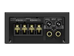
Gain Control
If the sound level is too low, even when the volume of the car stereo used along with this power amplifier is turned up, turn gain control on the front of the power amplifier clockwise. If the sound distorts when the volume is turned up, turn the gain control counter-clockwise.
- When using with an RCA equipped car stereo (standard output of 500mV ), set to the NORMAL position. When using with an RCA equipped Pioneer car stereo with max. output of 4V or more, adjust level to match the car stereo output level.
- For synchronized amplifier's gain control, see the "Setting the Gain for synchronized amplifier" section.
MODE SELECT Switch
You can select amplifier's sync mode from MASTER, SYNC and SYNC INV. For the position of the MODE SELECT switch, see the "Connecting the Speaker wires" section.
Bass Boost Level Control
Bass boost level control can boost the level around the frequency selected by the bass boost frequency control from 0 to 12dB
Bass Boost Frequency Control
You can select a bass boost frequency from 40 to 120Hz with the bass boost control.
Cut Off Frequency Control for LPF
You can select a cut off frequency from 40 to 240Hz
Slope Select Switch
You can select a slope for the LPF from -18 and -24 dB.
Subsonic Select Switch
The subsonic filter cuts inaudible frequencies below 20Hz to eliminate unwanted vibrations and minimize power loss.
Power Indicator
The power indicator lights when the power is switched on.
Connecting the Unit
CAUTION
- Disconnect the negative (-) terminal of the battery to avoid the risk of short-circuit and damage to the unit.
- Secure the wiring with cable clamps or adhesive tape. To protect the wiring, wrap adhesive tape around it where they lie against metal parts.
-
Do not route wires where they will get hot, for example where the heater will blow over them. If the insulation heats up, it may become damaged, resulting in a short-circuit through the vehicle body.
-
Make sure that wires will not interfere with moving parts of the vehicle, such as the gearshift, handbrake or seat sliding mechanism.
- Never feed power to other equipment by cutting the insulation of the power supply wire to tap from the wire. The current capacity of the wire will be exceeded, causing overheating.
- Never replace the fuse with one of greater value or rating than the original fuse. Use of an improper fuse could result in overheating and smoke and could cause damage to the product and injury including burns.
CAUTION:
To prevent damage and/or injury
- Do not ground the speaker wire directly or connect a negative () lead wire for several speakers.
- This unit is for vehicles with a 12-volt battery and negative grounding. Before installing it in a recreational vehicle, truck or bus, check the battery voltage.
- If the car stereo is kept on for a long time while the engine is at rest or idling, the battery may go dead. Turn the car stereo off when the engine is at rest or idling.
- If the system remote control wire of the amplifier is connected to the power terminal through the ignition switch (12 V DC), the amplifier will always be on when the ignition is on—regardless of whether the car stereo is on or off. Because of this, the battery could go dead if the engine is at rest or idling.
-
DO NOT connect a subwoofer with a lower impedance than specified in the "Connecting the Unit" section. Amplifier damage, smoke, and overheating could result from a non-specified connection. The amplifier surface could also become hot to the touch and minor burns could result.
-
Connect either of two subwoofoers to the amplifier; 1: a subwoofer with a 750W or larger nominal input and an impedance 4 , or 2: a subwoofer with a 1,500W or larger nominal input and an impedance 2 . If the nominal input and impedance are out of the above ranges, the subwoofer may catch fire, emit smoke or become damaged.
-
Install and route the separately sold battery wire as far away as possible from the speaker wires. Install and route the separately sold battery wire, ground wire, speaker wires and the amplifier as far away as possible from the antenna, antenna cable and tuner.
-
Cords for this product and those for other products may be different colors even if they have the same function. When connecting this product to another product, refer to the supplied Installation manuals of both products and connect cords that have the same function.
Connection Diagram
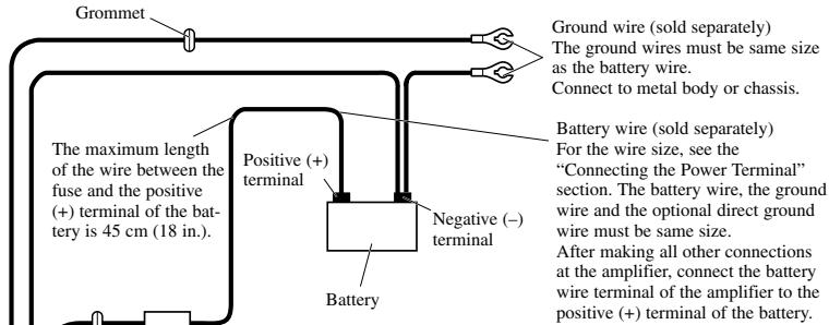
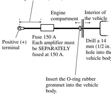
Grommet Fuse (150 A)
Each amplifier must be SEPARATELY
fused at 150A
Optional direct ground wire (sold separately) When chassis grounding is not sufficient,
direct grounding should be used. The wire size should be same size as the battery wire.
SYNC OUTPUT/
SYNC INPUT jack See the "Connecting the Speaker wires" section for SYNC OUTPUT / SYNC INPUT jack connection instructions.
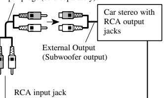
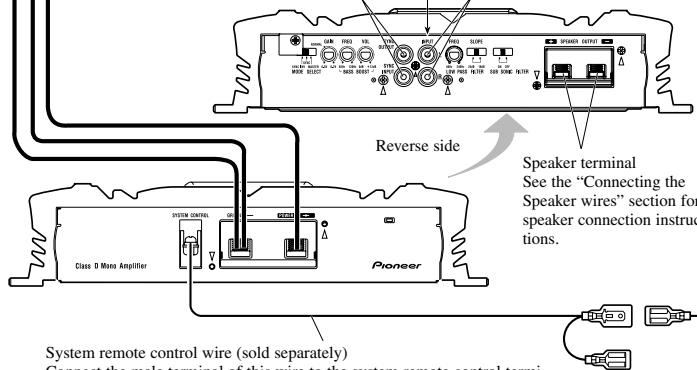
System remote control wire (sold separately)
Connect the male terminal of this wire to the system remote control terminal of the car stereo (SYSTEM REMOTE CONTROL). The female terminal can be connected to the auto-antenna relay control terminal. If the car stereo does not have a system remote control terminal, connect the male terminal to the power terminal through the ignition switch.
Connecting the Power Terminal
- Always use the recommended battery and ground wire, which is sold separately. Connect the battery wire directly to the car battery positive terminal (+) and the ground wire to the car body.
- Recommended wires size (AWG: American Wire Gauge) is as follows. The battery wire, the ground wire and the optional direct ground wire must be same size.
Battery Wire and Ground Wire Size
| Wire Length | less than 4 ft | 4-7 ft | 7-10 ft |
| less than 1.2 m | 1.2-2.1 m | 2.1-3.0 m | |
| Wire Size | 4 AWG | 4 AWG | 2 AWG |
| 10-13 ft | 13-16 ft | 16-19 ft | 19-22 ft |
| 3.0-3.9 m | 3.9-4.8 m | 4.8-5.7 m | 5.7-6.7 m |
| 2 AWG | 1 AWG | 1 AWG | 0 AWG |
1. Pass the battery wire from the engine compartment to the interior of the vehicle.
After making all other connections to the amplifier, connect the battery wire terminal of the amplifier to the positive (+) terminal of the battery.
The maximum length of the wire between the fuse and the positive (+) terminal of the battery is 45~cm (18 in.).
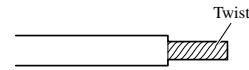
- Twist the battery wire, ground wire and system remote control wire.
3. Connect the wires to the terminal.
Before connecting the wires to the terminals, remove the endcap. After connecting the wires to the terminals, attach the endcap.
Fix the wires securely with the terminal screws.
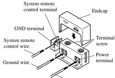
Battery wire

Failure to securely fasten the battery wire to the terminal using the terminal screws could cause the terminal area to overheat and could result in damage and injury including minor burns.
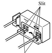
4. Put the wire ties in the slits and wrap the wire ties around the wires.
- Wrap the wire tie around the wire insulation, not the stripped wire.
Wire tie
Connecting the Speaker Terminals
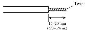
- Expose the end of the speaker wires using nippers or a cutter by about 15 - 20mm (5/8-3/4 in.) and twist.
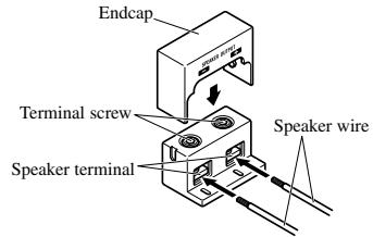
2. Connect the speaker wires to the speaker terminals.
- Before connecting the wires to the terminals, remove the endcap. After connecting the wires to the terminals, attach the endcap.
Fix the speaker wires securely with the terminal screws.
-
Put the wire ties in the slits and wrap the wire ties around the wires.
-
Wrap the wire tie around the wire insulation, not the stripped wire.
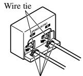
Slit
Setting the Gain for synchronized amplifier
After connecting the speaker wires, adjust each syncd amplifier's gain control. All syncd amplifiers follow the master amplifier's settings.
Quick Setup of the Gain
Set each synchronized amplifier's gain control to the NORMAL position. This setting will balance output volumes sufficiently for most applications.
Advanced Setup of the Gain
Starting with the master amplifier, adjust the gain control on each amplifier in order.
- Output sin wave through this system at low output level.
- Use volt meter to measure the master amplifier's output voltage level.
- Use volt meter to measure the synced amplifier's output voltage level.
- Match the synchronized amplifier's output to the master's output using the gain control on the synchronized amplifier.
- Repeat for the each synchronized amplifier in the proper order.
Connecting the Speaker wires
Connect the speaker leads to suit the configuration according to the figures shown below and the next page.
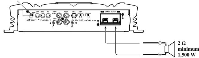
Single Amplifier
- Speaker wire size must be 10 AWG minimum.
- Load may be any combination of speakers but impedance must be 2 or larger.
MODE SELECT switch must be in
MASTER position.
Two Amplifier Bridged
- Speaker wire size must be 10 AWG minimum
- Load may be any combination of speakers but impedance must be 4 or larger.
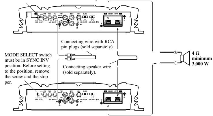
MODE SELECT switch must be in MASTER position.
Two Amplifier
- Speaker wire size must be 10 AWG minimum.
- Load may be any combination of speakers but impedance must be 2 or larger.
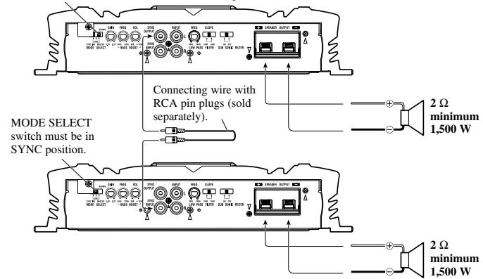
MODE SELECT switch must be in MASTER position.
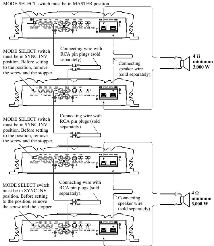
Four Amplifier Bridged
- Speaker wire size must be 10 AWG minimum.
- Load may be any combination of speakers but impedance must be 4 or larger.
Four Amplifier
- Speaker wire size must be 10 AWG minimum.
- Load may be any combination of speakers but impedance must be 2 or larger.
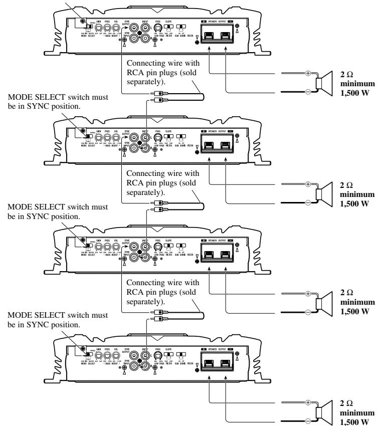
MODE SELECT switch must be in MASTER position.
Installation

CAUTION
- Do not install in:
Places where it could injure the driver or passengers if the vehicle stops suddenly.
Places where it may interfere with the driver, such as on the floor in front of the driver's seat
- Make sure that wires are not caught in the sliding mechanism of the seats, resulting in a short-circuit.
- Confirm that no parts are behind the panel when drilling a hole for installation of the amplifier. Protect all cables and important equipment such as fuel lines, brake lines and electrical wiring from damage.
- Install tapping screws in such a way that the screw tip does not touch any wire. This is important to prevent wires from being cut by vibration of the car, which can result in fire.
- DO NOT allow amplifier to come into contact with liquids due to, for example, the location where the amplifier is installed. Electrical shock could result. Also, amplifier and speaker damage, smoke, and overheating could result from contact with liquids. In addition, the amplifier surface and the surface of any attached speakers could become hot to the touch and minor burns could result.
- To ensure proper installation, use the supplied parts in the manner specified. If any parts other than the supplied ones are used, they may damage internal parts of the amplifier, or they may become loose causing the amplifier to shut down.
- Never replace the fuse with one of greater value or rating than the original fuse. Use of an improper fuse could result in overheating and smoke and could cause damage to the product and injury including burns.
CAUTION:
To prevent malfunction and/or injury
- To ensure proper heat dissipation of the amplifier, be sure of the following during installation.
-Allow adequate space above the amplifier for proper ventilation.
-Do not cover the amplifier with a floor mat or carpet. -
DO NOT allow amplifier to come into contact with liquids due to, for example, the location where the amplifier is installed. Electrical shock could result. Also, amplifier and speaker damage, smoke, and overheating could result from contact with liquids. In addition, the amplifier surface and the surface of any attached speakers could become hot to the touch and minor burns could result.
-
Do not install the amplifier on unstable places such as the spare tire board.
- The best location for installation differs with the car model and installation location. Secure the amplifier at a sufficiently rigid location.
- Make temporary connections first and check that the amplifier and the system operate properly.
- After installing the amplifier, confirm that the spare tire, jack and tools can be easily removed.
Example of installation on the floor mat or on the chassis
1. Place the amplifier where it is to be installed. Insert the supplied tapping screws (4× 18mm) into the screw holes. Push on the screws with a screwdriver so they make marks where the installation holes are to be located.
2. Drill 2.5mm (1/8 in.) diameter holes at the point marked, and install the amplifier, either on the carpet or directly to the chassis.
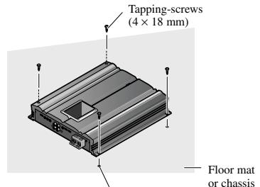
Drill a 2.5mm (1/8 in.)
diameter hole
Specifications
Power source 14.4 V DC (10.8 - 15.1 V allowable)
Grounding system Negative type
Current consumption 70 A (at continuous power, 4
Average current drawn* 10.6 A (4 Ω for one channel)
15.6 A (2 Ω for one channel)
Fuse 150 A
Dimensions 300 (W) × 64 (H) × 330 (D) mm
[12 (W) 3(H)× 13 D) in.
Weight 7.3 kg (16.0 lbs.) (Leads for wiring not included)
Maximum power output 1,500 W × 1 (4 Ω) / 3,000 W × 1 (2 Ω)
Continuous power output . 750W× 1 (at 14.4V,4 ,20 - 240Hz1.0% THD)
1,500 W × 1 (at 14.4 V, 2 Ω, 20 - 240 Hz 2.0% THD)
Load impedance 4Ω (2-8Ω allowable), (Ex. Bridge 4-16 Ω)
Frequency response 10 - 240 Hz (+0 dB, -1 dB)
S/N ratio 90 dB (IHF-A network)
Distortion 0.05% (50 W, 100 Hz)
Low pass filter Cut off frequency: 40 - 240Hz
Cut off slope: -18, -24 dB/oc
Subsonic filter (HPF) Frequency: 20Hz
Slope: -18 dB
Bass boost Level: 0 - 12 dB
Frequency: 40 - 120Hz
Phase control SYNC,SYNC INV
Gain control 200 mV - 6.5 V
Maximum input level / impedance .RCA: 6.5 V / 22 kO
Power output . 750 W RMS × 1 channel
(4Ω and ≤ 1% THD+N)
1500 W RMS × 1 channel
(2Ω and ≧ 1% THD+N, 240 Hz)
60 dBA (Reference: 1 W into 4 Ω)

Note:
- Specifications and the design are subject to possible modification without notice due to improvements.
*Average current drawn
- The average current drawn is nearly the maximum current drawn by this unit when an audio signal is input. Use this value when working out total current drawn by multiple power amplifiers.
Cher Client:
Pioneer Electronics (USA) Inc. CUSTOMER SUPPORT DIVISION
P.O.Box 1760
Long Beach, CA 90801-1760
800-421-1404
Canada
300 Allstate Parkway
Markham, Ontario L3R OP2
1-877-283-5901
- Owner's Manual
- PRS-D5000SPL
- Mode d'emploi
- PIONEER CORPORATION
- To establish a safe level:
- Once you have established a comfortable sound level:
- We Want You Listening For A Lifetime
- Decibel
- Level Example
- THE FOLLOWING NOISES CAN BE DANGEROUS UNDER CONSTANT EXPOSURE
- Before Using This Product
- Information to User
- Important
- After-sales service for Pioneer
- products
- U.S.A.
- CANADA
- Product registration
- http://www.pioneerelectronics.com
- About This Product
- CAUTION
- WARNING
- Gain Control
- MODE SELECT Switch
- Bass Boost Level Control
- Bass Boost Frequency Control
- Cut Off Frequency Control for LPF
- Slope Select Switch
- Subsonic Select Switch
- Power Indicator
- Connecting the Unit
- CAUTION:
- To prevent damage and/or injury
- Connection Diagram
- Connecting the Power Terminal
- Pass the battery wire from the engine compartment to the interior of the vehicle.
- Connect the wires to the terminal.
- Put the wire ties in the slits and wrap the wire ties around the wires.
- Connecting the Speaker Terminals
- Connect the speaker wires to the speaker terminals.
- Setting the Gain for synchronized amplifier
- Quick Setup of the Gain
- Advanced Setup of the Gain
- Connecting the Speaker wires
- Single Amplifier
- Two Amplifier Bridged
- Two Amplifier
- Four Amplifier Bridged
- Four Amplifier
- Installation
- To prevent malfunction and/or injury
- Example of installation on the floor mat or on the chassis
- Place the amplifier where it is to be installed. Insert the supplied tapping screws (4× 18mm) into the screw holes. Push on the screws with a screwdriver so they make marks where the installation holes are to be located.
- Drill 2.5mm (1/8 in.) diameter holes at the point marked, and install the amplifier, either on the carpet or directly to the chassis.
- Specifications
- Note:
- *Average current drawn
- Cher Client:
Brand : PIONEER
Model : PRS-D5000SPL
Category : Car amplifier