
AZSG10020 - Alarm system ABUS - Free user manual and instructions
Find the device manual for free AZSG10020 ABUS in PDF.
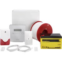
| Product type | ABUS wired indoor siren |
| Brand | ABUS |
| Model | AZSG10020 |
| Category | Alarm system |
| Dimensions (W x H x D) | 115 x 138 x 36 mm |
| Weight | 174 g |
| Power supply | 9 V – 15 V DC |
| Current consumption (siren + strobe) | 100 mA (at 12 V DC) |
| Sound pressure | 90 dB(A) at 1 m |
| Maximum alarm sound duration | 15 minutes |
| Protection rating | IP34 (indoor, when mounted) |
| Housing material | Polycarbonate |
| Operating temperature | -15 °C to +40 °C |
| Max. air humidity | 95 % |
| Main functions | Siren, strobe, adjustable rising or continuous sound signal, front and rear tamper detection |
| Mounting | Flush mounting |
| Connection | Screw terminal, fixed wiring |
| Status LED consumption | 4 mA (at 12 V DC) |
| Maintenance | Periodic test, check tamper contacts |
| Warranty | 2 years |
| Safety | Tamper switch, installer mode required before maintenance |
| Compliance | EMC Directive 2014/30/EU, RoHS 2011/65/EU, WEEE 2012/19/EU |
| Package contents | Siren, quick start guide, safety instructions, mounting hardware |
Frequently Asked Questions - AZSG10020 ABUS
User questions about AZSG10020 ABUS
0 question about this device. Answer the ones you know or ask your own.
Ask a new question about this device
Download the instructions for your Alarm system in PDF format for free! Find your manual AZSG10020 - ABUS and take your electronic device back in hand. On this page are published all the documents necessary for the use of your device. AZSG10020 by ABUS.
USER MANUAL AZSG10020 ABUS
Safety information ....4
Scope of delivery 5
Technical data 5
Features 6
Installation 8
Maintenance 10
Warranty....10
Disposal 11
Declaration of conformity ....11
Notes 11
Introduction
Information on user guide
Dear Customer,
Thank you for purchasing this product. This device is built with state-of-the-art technology.
These instructions contain important installation and operation information (as at 04/2018). Follow the directions and instructions in this user manual to ensure safe operation. Store this manual in a safe place for future reference. This manual constitutes part of the device. If you pass the device on to third parties, please remember to include this manual.
Intended use
Only use the device for the purpose for which it was built and designed. Any other use is considered unintended.
This product complies with current domestic and European regulations. Conformity has been certified, and all related certifications are available from the manufacturer on request.
To ensure this condition is maintained and that safe operation is guaranteed, it is your obligation as the user to observe this user guide. If you have any questions, please contact your specialist dealer. Further general information and information on product support can be found at www.abus.com on the general page or for dealers and installers, in the Partner portal.

Please observe the notes and instructions in this user manual! If you do not follow these instructions, any guarantee claim is invalidated. No liability can be accepted for resulting damage.
No part of the product may be changed or modified in any way.
Please observe the local legal requirements. In some European countries, the use of alarms outdoors is prohibited or the maximum alarm duration is limited. Please consult your local authorities on this.
Set the alarm panel to installer mode before starting any installation or maintenance work. Installer mode prevents alarms from being activated when the repeater's cover is opened
Limitation of liability
Everything possible has been done to ensure that the content of these instructions is correct. However, neither the author nor ABUS Security-Center GmbH & Co. KG can be held liable for loss or damage caused by incorrect or improper installation and operation or failure to observe the safety instructions and warnings. No liability can be accepted for resulting damage. No part of the product may be changed or modified in any way. If you do not follow these instructions, your warranty claim becomes invalid.
Subject to technical modifications.
© ABUS Security-Center GmbH & Co. KG, 04/2018.
Safety information
Explanation of symbols
The following symbols are used in this manual and on the device:
| Symbol | Signal word | Meaning |
 | Danger | Indicates a risk of injury or health hazards. |
 | Danger | Indicates a risk of injury or health hazards caused by electrical voltage. |
 | Important | Indicates possible damage to the device/accessories. |
 | Note | Indicates important information. |
 | The EU Directive WEEE 2012/19/EC governs the proper recovery, treatment and recycling of used electronic devices. This symbol means that, in the interest of environmental protection, the device must be disposed of separately from household or industrial waste at the end of its lifespan in accordance with applicable local legal guidelines. Used devices can be disposed of at official recycling centres in your country. Obey local regulations when disposing of material. Further details on returns (also for non-EU countries) can be obtained from your local authority. Separate collection and recycling conserve natural resources and ensure that all the provisions for protecting health and the environment are observed when recycling the product. |
Packaging
Danger
Keep packaging material and small parts away from children. There is a risk of suffocation.
Remove all packaging material before using the device.
Scope of delivery
| • ABUS Wired Indoor Sounder | • Safety information |
| • Quickstart guide | • Installation material |
Technical data
| Product name | ABUS Wired Indoor Sounder | |
| Product description | Signal generator | |
| Item number | AZSG10020 | |
| Environmental class | II | |
| Operating temperature | -15 °C to +40 °C | |
| Humidity, maximum | max. 95 % | |
| Housing material | Polycarbonate | |
| Dimensions (W x H x D) | 115x138x36 mm | |
| Weight | 174 g | |
| Sound pressure | 90 dB(A) @ 1 m | |
| Maximum duration of the acoustic alarm | 15 minutes | |
| Protection class | IP34 (internal spaces, in its installed state) | |
| Power consumption | Power consumption of just siren | 84 mA (at 12 V DC) |
| Power consumption of just flashing light | 17 mA (at 12 V DC) | |
| Power consumption of flashing light and siren | 100 mA (at 12 V DC) | |
| Power consumption for status display | 4 mA (at 12 V DC) | |
| Operating voltage | 9 V–15 V DC | |
| EU Directives | EMC: 2014/30/EU | |
| RoHS: 2011/65/EU | ||
| WEEE: 2012/19/EU | ||
Features
Features
General
This indoor sounder is an indoor combination alarm device with sounder and flashing light for use with burglar alarm systems. It serves as an optical and acoustic alarm. The sounder and alarm panel communicate via cableways, so fixed wiring is required between the two units. The ABUS Wired Indoor Sounder is intended for wall installation.
Main features
-
Simple installation
• 90 dB(A) sound pressure -
Tamper detection for front and rear sides
- Shock-resistant construction from polycarbonate

Incorrect or unclean installation work may lead to erroneous interpretation of signals, the consequences of which may include false alarms. The costs incurred by potential dispatches of rescue services, such as the fire service or police, must be borne by the operator of the system.
Device description – Sounder
| 1 | Mounting holes for wall installation |
| 2 | Acoustic sounder |
| 3 | Terminal 2 (J2) |
| 4 | Terminal 1 (J1) |
| 5 | Tamper switch |
| 6 | LEDs |
| 7 | Housing screw and cover |
| 8 | Jumper (SW1) |

Terminal 2 (J2) is not provided in an earlier version of the Wired Indoor Sounder AZSG10020.
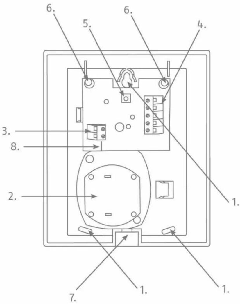
Figure 1: Overview of the sounder
Installation
Installation
Installing the sounder
Step 1: Select installation location for the sounder
Select an installation location which:
- is inaccessible to intruders and vandals.
- can be reached with cabling.
Step 2: Open the sounder's cover
- Open the cover for the housing screw on the lower side (see Fig. 1).
- Remove the screws and open the cover by lifting it upwards.
Step 3: Mount the sounder on the wall

A predetermined breaking point fixed for wall installation by the upper screw serves as an anti-removal wall contact.
- Position the sounder on the wall. Mark the three fixing points.
- Drill the holes in the wall to fit the diameter of the screw anchors. Insert the screw anchors supplied, in the holes.
- Feed the cable provided in the inner housing through the cable inlet on the reverse side.
- Insert the screws supplied through the sounder's fixing holes. Turn the screws in the screw anchors. Do not tighten the screws yet.
- Align the sounder using a spirit level. Now tighten the screws.
Step 4: Pre-configuration via jumper
On the "SW1" jumper (Fig. 1), there are two options for positioning the jumper:
S1: If the jumper is in contact with the upper two PINs (S1), the following setting is thus selected: Increasing signal tone. This means that the tone pulsates and produces the standard sounder signal.
S2: If the jumper is in contact with the lower two PINs (S2), the following setting is thus selected: Continuous signal tone. This means that the tone builds up once and then maintains its frequency; it sounds a continuous signal.
Step 5: Connecting the cable
- Strip the cable to sufficient length and remove insulation from the individual wires in order to connect these.
- Connect the individual wires to the respective screw terminals.
- The assignment of the terminal connectors can be found here.
Description of the terminals:
Terminal 1 (J1):
Terminal 1 includes five screw terminals that are available for the standard functions of the wired indoor sounder. In order to activate the sounder and/or the flashing light, connect the screw terminal "C -ve" to 0 V and the appropriate screw terminal "S +ve" or "F +ve" to 12 V on the alarm panel. The screw terminals for the sounder and the flashing light can be wired together or separately. If wiring together, bridge the two connector clamps.
| S +ve | 12 V coming from the alarm panel to activate the sounder |
| F +ve | 12 V coming from the alarm panel to activate the flashing light |
| C -ve | 0 V to the alarm panel |
| Sabotage | Output of the tamper contact (NC) |
| Sabotage | Output of the tamper contact (NC) |
Terminal 2 (J2):
Terminal 2 includes two additional screw terminals that can be connected to a separate 12 V power supply from the alarm panel. As a result, the LEDs of the wired indoor sounder are permanently illuminated at a lower intensity. If terminal 1 has been wired as described above, the standard function of terminal 1 overlays the function of terminal 2, so that the flashing light is activated in the event of an alarm. Terminal 2 can be used, for example, to display the status of the burglar alarm system (e.g. system armed/disarmed).

Only use these two screw terminals when you want the LEDs to be permanently illuminated. If the LEDs are not supposed to be illuminated in standby mode, please only wire up terminal 1.
Terminal 2 is not provided in an earlier version of the Wired Indoor Sounder AZSG10020 In this earlier version, the additional function of terminal 2 can therefore not be used.
| -ve | 0 V – the LEDs are permanently illuminated |
| +ve | 12 V – the LEDs are permanently illuminated |
Step 6: Closing the sounder
- Mount the sounder cover from above and attach it at the bottom.
- Now fix the cover using the screw by means of the housing attachment on the underside.
Maintenance

Danger
Be prepared, that the alarm will be activated as soon as you open the sounder's cover. Make sure that any loud sounds emitted will not startle you.
- Test, during routine maintenance, that the sounder works properly.
- Check the tamper contacts
• Test the acoustic and visual alarm
Warranty

Note
ABUS products are designed and manufactured with the greatest care and tested according to the applicable regulations.
The warranty only covers defects caused by material or manufacturing errors at the time of sale. If there are demonstrable material or manufacturing errors, the module will be repaired or replaced at the guarantor's discretion.
In such cases, the warranty ends when the original warranty period of two years expires. All further claims are expressly rejected.
ABUS will not be held liable for defects and damage caused by external influences (e.g. transport, use of force, operating errors), inappropriate use, normal wear and tear, or failure to observe the instructions in this manual.
In the event of a warranty claim, the original proof of purchase with the date of purchase and a short written description of the problem must be supplied with the product.
If you discover a defect on your wired indoor sounder which existed at the time of purchase, contact your dealer directly within the first two years following purchase.
Disposal

Dispose of the device in accordance with EU Directive 2012/19/EC – WEEE (Waste Electrical and Electronic Equipment). If you have any questions, please contact the municipal authority responsible for disposal. You can get information on collection points for waste equipment from your local authority, from local waste disposal companies or your dealer, for example.
Declaration of conformity
ABUS Security-Center GmbH & Co. KG hereby declares that the device with item number AZSG10020 complies with the essential requirements and other relevant provisions of Directives 2011/65/EU, 2014/30/EU. The full EU Declaration of Conformity text can be found at: www.abus.com > Item search > AZSG10020 > Downloads
The Declaration of Conformity can also be obtained from the following address:
ABUS Wired Indoor Sounder
Installation instructions and user manual
ABUS Wired Indoor Sounder
Installation instructions and user manual
Figur 1: Overblik over sirenen
Montering
Montering
Installation af sirenen


- Introduction
- Information on user guide
- Intended use
- Limitation of liability
- Safety information
- Explanation of symbols
- Packaging
- Danger
- Features
- General
- Main features
- Installation
- Installing the sounder
- Step 1: Select installation location for the sounder
- Step 2: Open the sounder's cover
- Step 3: Mount the sounder on the wall
- Step 4: Pre-configuration via jumper
- Step 5: Connecting the cable
- Description of the terminals:
- Terminal 1 (J1):
- Terminal 2 (J2):
- Step 6: Closing the sounder
- Maintenance
- Warranty
- Note
- Disposal
- Declaration of conformity
- ABUS Wired Indoor Sounder
- Montering
- Installation af sirenen
Brand : ABUS
Model : AZSG10020
Category : Alarm system