Floodlight LC1 - Surveillance Camera EZVIZ - Free user manual and instructions
Find the device manual for free Floodlight LC1 EZVIZ in PDF.
User questions about Floodlight LC1 EZVIZ
0 question about this device. Answer the ones you know or ask your own.
Ask a new question about this device
Download the instructions for your Surveillance Camera in PDF format for free! Find your manual Floodlight LC1 - EZVIZ and take your electronic device back in hand. On this page are published all the documents necessary for the use of your device. Floodlight LC1 by EZVIZ.
USER MANUAL Floodlight LC1 EZVIZ
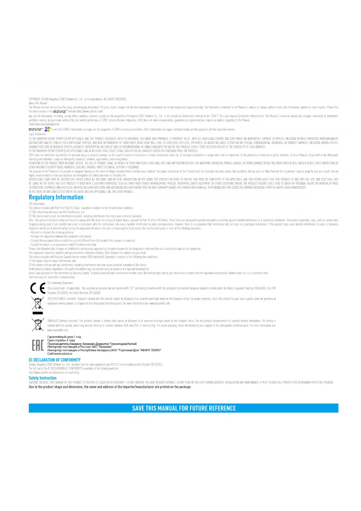
COPYRIGHT ©2018 Fangzhou / 507 Software Co., Ltd. or its subsidiaries. ALL RIGHTS RESERVED. About this Manual
The Manus, includes instructions for using and managing the product. Pictures, charts, images and all other information hereinafter are in description and explanation only. The information contained in the Manual is subject to change, without notice, due to firmware updates or other reasons. Please find the latest version in the EZVIZ™ website (http://www.xvizide.com).
Any and all information, including, among others, writings, pictures, scenes are the properties of hangboa, FNV7 Software Co., Ltd., or is subsidiaries herein for referred to be "FNV7". This case manual, herein is referred to be "the Manual" cannot be reproduced, charged, translated, or distributed, partially or wholly, by any means, without the prior written permission at FNV7. Unless otherwise stipulated, FNV7 does not make any warranties, guarantees or representations, express or implied, ingoering to the Manual Information Acknowledgement
ezviz™, and other EZIE's trademarks and logos are the properties of EZIE in various jurisdictions. Other trademarks and logos mentioned below are the properties of their respective owners.
Legal Disclaimer
TO THE MAXIMUM EXTENT PERMITTED BY APPLICABLE JAW, THE PRODUCT DESCRIBED WITH ITS HARDWARE, SOFTWARE AND FEMMWARE, IS PROVIDED "AS IS", WITH ALL FAULTS AND ERRORS, AND EVIZ MAKES NO WARRANTIES, EXPRESS OR IMPLIED, INCLUDING WITHOUT LIMITATION, MERCHANTABILITY SAUTSABORATORY QUALITY, FITNESS FOR A PART CULAR PURPOSE, AND NON-INFRINGEMENT OF THIRD PARTY. IN NO EVENT WILL EXEVE ITS DIRECTORS, OFF CERS, EMPLOYEES, OR ASSETS BE LIABLE TO YOU FOR ANY SPECIAL CONSEQUENTIAL, INDICENTAL, OR INDIC REJECT DAMAGES, INCLUDING ANOTHERS, CAMPOSIS FOR LIFE OF BUSINESS PROFITS, BUSINESS INTRODUCTION, OR LOSS OF DATA OR DOCUMENTATION, IN CONNECTION WITH THE USE OF THIS PRODUCT (WITH ECONOMESTANCE) AS SPECIFICATIONS ARE AVAILABLE.
TO THE MAXIMUM EXTENT PERMITTED BY APPLICABLE LAW, IN NO EVENT SHALL FLY'S TOTAL LIABILITY FOR ALL DAMAGES EXCEED THE PURCHASE PRICE THE PRODUCT.
EFN7 does not unclear any liquidity or personal injury or property damage, as the result of product interruption or service termination cause by: a improper installation or usage other than as requested; of the protection of national or public interests; of Force Majune of yourself or the third party, including not limitation, using any third party's products, software, applications, and among others.
REGARDING TO THE PRODUCT WITH INTERNET ACCESS, THE USE OF PRODUCT SHALL BE WHOLLY AT YOUR OWN RISKS. EZVIZ SHALL NOT TAKE ANY RESPONSIBILITES FOR ABNORMAL OPERATION. PRIVACY LEAKAGE OR OTHER DAMAGES RESULTING FROM CYBER ATTACK, HACKER ATTACK, VIRUS INSPECTION, OR OTHER INTERNET SECURITY RISKS. HOWEVER, EZVIZ WILL PROVIDE TIMELY TECHNICAL SUPPORT IF REQUIRED.
The purpose of the Products is to provide a adequate warning in the event of illegal encroachment in certain area; however, the proper installation of the Products will not eliminate, but only reduce that accidents will not occur or that there will be no personal injury or property loss as a result. You are highly recommended to raise your vigilance and strengthen the safety awareness in the daily life.
SURVEILLANCE LAMPS WARY BY JURSDICTON, PLEASE CHECK ALL RELENTN LASYS IN YOUR JURSDICTON BEFORE USING THIS PRODUCT IS ORDER TO ENSHRE THAT YOUR USE CONFORMS TO THE APPLICABLE LAW. YOU FURTHER AGREES THAT THIS PRODUCT IS ONLY FOR CIVIL USE, AND LEAV SHALL NOT BE LIABLE IN THE LEVEL THAT THIS PRODUCT IS USED WITH ILLETIC IMATES PURPOSES, SUCH AS THIRD PARTY RIGHTS INFRINGEMENT, MEDICAL EPLANISM, SOLED EQUIPMENT OR OTHER SIGUATIONS WHICH THE PRODUCT FAILURE COULD TO DEATH OR PERSONAL INJURY OR VEGETION OF MASS STRUCTURAL CHEMICAL AND BIOLOGICAL AVAPATORY NUCLEAR EXPLOSION, ARE ANY IMPROSE THE NUTTER ENERGY EXCLUSIONS ON ANOTHER UNLESSY SHOULD HAVE SLIKE ALL RESPONSIBLE LIFE FOR LOSSES OR DAMAGES RESOLUING FROM THE ABOVE LIGERS WITHOUT SURVEIL
IN THE EVENT OF ANY CONFLICTS BETWEEN THE ABOVE AND THE APPLICABLE LAW, THE LATER PREWALS
Regulatory Information
FCC information
This device complies with Part 1b of the FCS Rules. Direction is subject to the following two conditions:
[1] This device may not cause harmful interference, and
(2) This device must accept any interference received, including interference that may cause undesired operation.
Note: This product has been tested and found to comply with the limits for a Class B digital voice, pursuant to Part 10 of the H2C Rules. These limits are designed to provide reasonable protection against harmful interference in a residential installation. This product generates, uses, and can radiate radio frequency energy and, if not installed and used in accordance with the instructions, may cause harmful interference to rise communications. However, there is no guarantee that interference will not occur in a particular installation. If this product does cause harmful interference to radio or television reception, which can be deemed by turning the equipment off and on, the user is encouraged to try to correct the interference by one or more of the following measures:
— Reorient or reactivate the receiving antenna.
—Increase the separation between the equipment, and receiver.
Connect the equipment into a outlet on a circuit different from that to which the receiver is connected.
—Consult the dealer or an experienced radio/IV technician for help.
Please take attention that changes or modification not expressly approved by the party responsible for compliance could void the user's authority to operate the equipment
This equipment should be installed and operated with a minimum distance 70cm between the radiator and your body.
This device comprises with Industry Canada (evenue-exempt: 935 standards). Operation is subject in the following two conditions:
(1) this device may not cause tolerance, and
[2] this device must accept any interference, including interference that may cause undesired operation of the device.
Under Industry Canada regulations, this radio transmitter may only operate using an antenna of a type and maximum for
lesser gain approved for the transmission by Industry Canada. To reduce potential, radio interference to other users, the antenna type and its gain should be so chosen that the equivalent, scotropically, radiocic power (e.g.) is not more than that necessary for successive communication.

EU Conformity Statement.
This product and - if applicable - the supplied accessories too are marked with "CE" and comply therefore with the applicable harmonizer. European standards listed under the Radio Equipment Directive 2014/53/EU, the EPIC Directive 2014/30/EU, the RJHS Directive 2011/65/EU.

2012/19/EU [WEEE directive]. Products marked with this symbol cannot be disposed of as conserved municipal waste in the European Union. For proper recycling, return this product to your local supplier upon the purchase of equivalent new equipment, or dispose of it at designated collection points. For more information see www.recyclathis.info.

2016/36/E/C (battery directive): This product contains a battery that cannot be disposed of as unsorted municipal waste in the European Union. See the product documentation for specific battery information. The battery is marked with this symbol, which may include, ettering to indicate cadmium (CoI, lead PbO, or mercury [Hg]). For proper recycling, return the battery to your supplier or to a designated collection point. For more information see: www.recyclotris.info.

EC DECLARATION OF CONFORMITY
hereby, Langphot, FNV Software Co., Ltd. declares that the radio equipment type [CS-IC] is a compliance with Directive 2014(53)U.
The full text of the PC RECLARATION OF CONFORMITY is available as the following web link:
http://www.eavife.com/deration-of-convunity.
Safety Instruction
CAUTION: THE BLUE LIGHT DAMAGE OF THIS PRODUCT TO THE EYES IS D. ASSISTED AS CATEGORY 1. DO NOT OBSERVE THE LIGHT IN SHORT DISTANCE, DO NOT TURN ON THE LIGHT DURING ASSEMBLY. INSTALLATION AND MAINTENANCE, IF MUST, PLEASE FULLY PROTECT EYES BY AWARDS PROTECTIVE EYES/ATAY. Due to the product shape and dimension, the name and address of the importer/manufacturer are printed on the package.
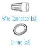
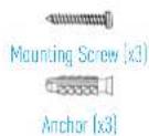
What's in the Box
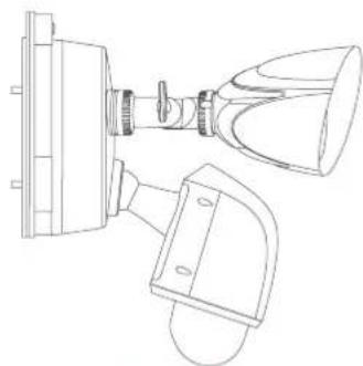
natural_image
Technical line drawing of a mechanical device with no visible text or symbolsSecurity Light Camera
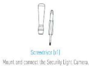
text_image
Screwdriver [x1] Mount and connect the Security Light Camera.
Security Light Camera
text_image
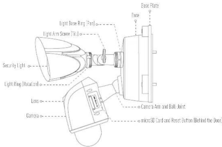
Base Plate Base Light Base Ring (Pan) Light Arm Screw (Tilt) Security Light Light Ring (Rotational) Lens Camera Camera Arm and Ball Joint microSD Card and Reset Button (Behind the Door)Name Description
| Light Base Ring (Pan) | Loosen the base ring and pan up to 360°. Tighten the base ring when you have the light panned the way you want. |
| Light Arm Screw (Till) | Loosen the arm screw and tilt the arm up to 180°. Tighten the screw when you have the arm in the position you want. |
| Light Ring (Rotation) | Loosen the light ring and rotate the light up to 360°. Tighten the screw when you have the light in the position you want. |
| Camera Arm and Ball Joint | Move the camera arm in its ball joint until you have the camera in the position you want.Make sure the base ring and adjustment screws are tightened all the way for each adjustment before proceeding. |
| microSD Card | Recommended compatibility: Class 10, Max.128CB.Initialize the card in the EZMZ app before using it. |
| Reset Button | Hold for 5 seconds to restart and reset all parameters to default. |

Security Light Camera Installation
EN
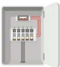
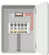
Step1 Shut off the electricity at the breaker that controls security light's circuit.
natural_image
Illustration of an open electrical control box with multiple panels and wiring (no text or symbols)Step2 Separate the base plate from the security light camera.
- Unscrew the 3 base screws.
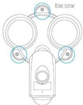
text_image
Base screw- Pull the security light camera off the base plate and unplug the 3-wire connector from the base.
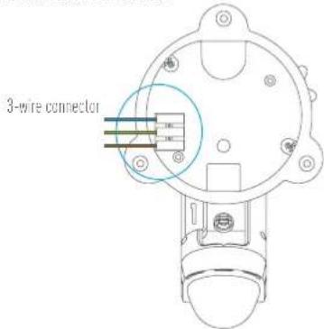
text_image
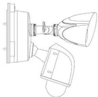
3-wire connector- After separating the base plate from the camera, the effect picture is shown as below.
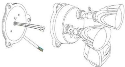
natural_image
Technical line drawings of mechanical components including a flange, cable, and housing (no text or symbols)Step3 Fix the base plate to the wall.
- Pick a clean and flat surface.
- Drill two holes and insert anchors.
- Fix the base plate to the wall with o-ring and mounting screws.
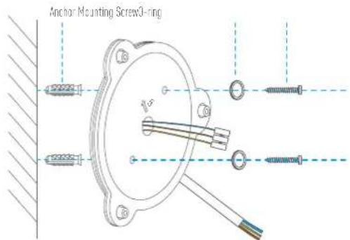
text_image
Anchor Mounting Screw0-ring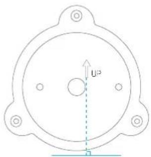
text_image
U²When installing the base plate, make sure the logo (JP) faces upward.
Recommended Installation Height: 10 feet (3 m) above the ground.
Recommended Drill Bit: 06 spec drill bit
Recommended Hole Depth: 0.13 feet to 0.14 feet (40 to 43 mm).

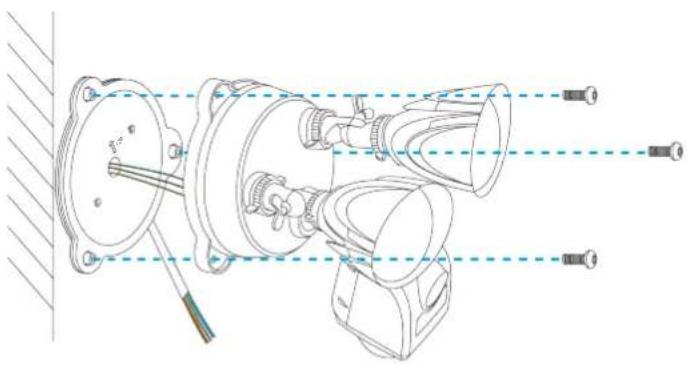
Step4 Mount the security light camera to the base plate
- Plug the 3-wire connector back into the security light camera as shown. Make sure it's completely sealed before proceeding.
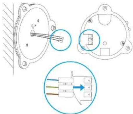
text_image
Technical diagram showing three views of an electrical component with labeled pins and wiring connections- Fix the security light camera to the base plate with base screws.
natural_image
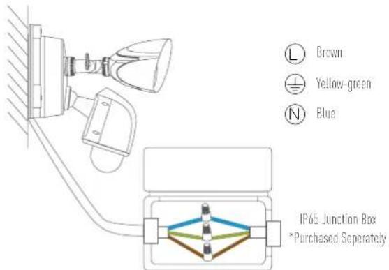
Technical line drawing of a mechanical assembly with no visible text or symbolsStep5 Connect the junction box and the base 3-wire connector
- Match each color wire from the base plate to the same color from the junction box [blue to blue, yellow-green to yellow-green, brown to brown].

text_image
L Brown Yellow-green N Blue IP65 Junction Box *Purchased Separately- You may use the wire connector for special junction box, then connect the wires as below.
text_image
L Brown Yellow-green N Blue IP65 Junction Box *Purchased SeparatelyStep6 Turn on power to your security light's circuit.
natural_image
Illustration of an open electrical control panel with multiple switches and wiring (no text or symbols)Put the ends of each pair into the wire connector, then twist it slightly.
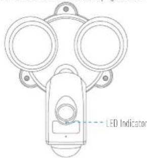
Step7 Confirm the security light camera has power
At first power up, the security lights turn on, when the security lights turn off and the LCD indicator on the front of the camera flashes blue, the security light camera is ready for setup.
text_image
LED IndicatorIf you've installed the security light camera on a switchable outlet, make sure you turn the outlet on and leave it on for the security light camera to function 24/7.
Security Light Camera Setup
EN
1. Create an user account
- Connect your mobile phone to Wi-Fi.
- Download and install the EZVIZ app by searching "EZVIZ" in App Store or Google Play™.
- Launch the app and register for an EZVIZ user account following the start-up wizard.
2. Add a security light camera to EZVIZ
- Log in the EZVIZ app
- From the EZVIZ app Home screen, tap "+" on the upper-right hand corner to go to the scan QR code interface.
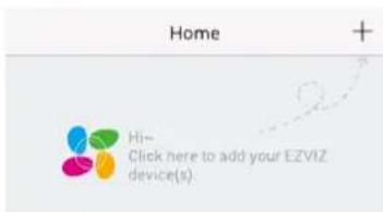
text_image
Home + Hi- Click here to add your EZVIZ device(s)- Scan the OR Code on the the security light camera.
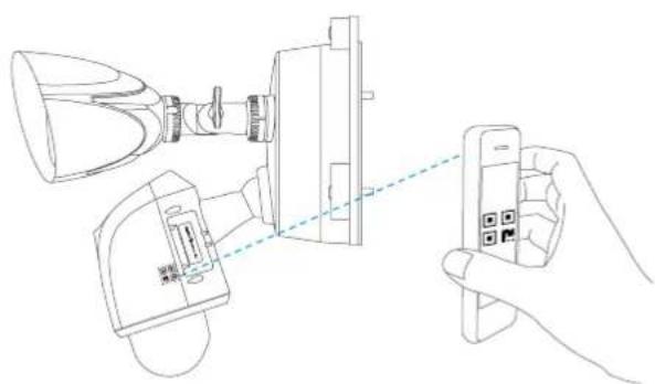
natural_image
Line drawing of a hand holding a smartphone connected to a device with a lamp and connector (no text or symbols)Follow the EZVIZ app wizard to finish Wi-Fi configuration.
If you want to change your security light camera's Wi-Fi, press and hold the reset button for bs and repeat this part.
- The security light camera works with 2.4GHz Wi-Fi signals. If you have a dual-band router with separate 2.4GHz and 5GHz networks, make sure your phone is connected to the 2.4GHz one.
- If your Wi-Fi network signal is less than 50% where you want to install the security light camera, a Wi-Fi signal, extender is recommended to boost the signal at the installation point.

Appendix
Install Memory Card (Optional)
- Remove the door on the side of the camera.
- Remove the silicone plug
- Insert a microSD card into the slot until a click.
- Put the silicone plug back and make sure it is fully plugged in the SD card slot.
- Place the door cover back on.
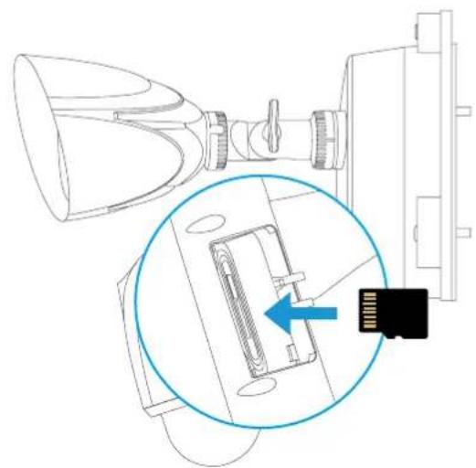
natural_image
Technical line drawing of a device with a magnified inset showing internal components (no text or symbols)Initialize Memory Card
- In the EZVIZ app, check the memory card status by tapping on the Storage Status in the Device Settings interface.
| Wi-Fi Configure | TEST-WiFi |
| Storage Status | |
| Device Version | Vx.xx build xxxxxxNo new version |
- If the memory card status displays as Uninitialized, tap to initialize it. The status will then change to Normal.
i For detailed information, please visit www.evizlife.com.

Lieferumfang
natural_image
Technical line drawing of a mechanical device with no visible text or symbolsnatural_image
Illustration of an open electrical control box with multiple panel indicators and a red circuit line (no text or symbols)natural_image
Technical line drawings of mechanical components, including a flanged housing and multi-chamber assembly (no text or symbols)text_image
Technical diagram showing three views of an electrical connector with labeled pins and a magnified inset illustrating the internal structure.natural_image
Illustration of an open electrical control box with multiple switches and a red circuit line (no text or symbols)text_image
Home + Hi- Click here to add your EZVIZ device(s)natural_image
Line drawing showing a hand holding a smartphone connected to a device with a lamp and connector (no text or symbols)natural_image
Technical line drawing of a device with a magnified inset showing internal components (no text or symbols)Speicherkarte formatieren
natural_image
Technical line drawing of a mechanical device with no visible text or symbolsnatural_image
Illustration of an open electrical control box with multiple panel indicators and a red circuit line (no text or symbols)ES
natural_image
Technical line drawings of mechanical components, including a flange and three views (no text or symbols)Paso 3 Fije la placa de base a la pared.