
TYWK5P1RW - TV PANASONIC - Free user manual and instructions
Find the device manual for free TYWK5P1RW PANASONIC in PDF.
| Product type | Wall mount bracket for plasma television |
| Brand | Panasonic |
| Model | TY-WK5P1RW |
| Type | Adjustable angle |
| Weight | 3.2 kg |
| Width | 550 mm |
| Height | 446 mm |
| Depth | 103.5 mm |
| Angle of tilt | 0 to 20 degrees (in 5-degree increments) |
| Compatibility | Panasonic plasma televisions (see manual pages 80-81) |
| Wall mounting | Screws with nominal diameter 6 mm (not supplied) |
| Number of fixing points | 6 |
| Tightening torque (bracket assembly) | 1.2 to 1.5 N·m |
| Tightening torque (TV fixing) | 3 to 4 N·m |
| Maximum operating temperature | 40 °C |
| Maintenance | Soft dry cloth, diluted neutral detergent if needed |
| Safety | Installation by a qualified professional recommended |
| Accessories included | Screws, washers, hex key |
| User manual | Included |
Frequently Asked Questions - TYWK5P1RW PANASONIC
User questions about TYWK5P1RW PANASONIC
0 question about this device. Answer the ones you know or ask your own.
Ask a new question about this device
Download the instructions for your TV in PDF format for free! Find your manual TYWK5P1RW - PANASONIC and take your electronic device back in hand. On this page are published all the documents necessary for the use of your device. TYWK5P1RW by PANASONIC.
USER MANUAL TYWK5P1RW PANASONIC
natural_image
Technical line drawing of a mechanical frame assembly (no text or symbols)Model No.
TY-WK5P1RW
| Fitting InstructionsPlasma TV wall-hanging bracket (Adjustable angle type) | English |
| Anleitung zur AnbringungWandhalterung zum Anbringen des Plasma-Fernsehers(Typ mit einstellbarem Winkel) | Deutsch |
| Montage-instructiesMuurbevestigingssteun voor plasmatelevisie(met verstelbare montagehoek) | Nederlands |
| Istruzioni per il montaggioSupporto per il montaggio a parete del televisore al plasma(con angolazione regolabile) | Italiano |
| Instructions de montageApplique de fixation au mur du téléviseur à plasma(Type à angle réglable) | Français |
| Instrucciones de instalaciónSoporte para colgar el televisor de plasma en una pared(Tipo de ángulo ajustable) | Español |
| Instruções de montagemSuporte de instalação na parede do televisor com ecrã deplasma (Com ângulo ajustável) | Português |
| MonteringsanvisningarVäggupphängningshållare för plasmatelevision(vinklingsbar typ) | Svenska |
| OpsætningsinstruktionerVægophæng til plasma-tv (justerbar vinkeltype) | Dansk |
| Инструкция по установкеКронштейн для настенного крепления широкоформатногоплазменного телевизора (Модель с регулируемым углом) | Русский |
| Орнату нүсқауларыПлазмалық теледидардың қабырғаға бекітетін кронштейні(Бұрышы реттелетін түрі) | Казахский |
| Інструкції з встановленняНастінний кронштейн для плазмового телевізора(З можливістю регулювання кута нахилу) | Українська |
| 安装施工说明书壁挂式框架(角度可调型) | 中文 |
| Hướng dẫn lắp đặtGiá dõ’ treo tưởng TV Plasma (loại góc có thể điều chỉnh) | Тếng Việt |
| Before commencing work, carefully read these Instructions and the Manual for the plasma TV to ensure that fitting is performed correctly. (Please save these instructions. You may need them when maintaining or moving the bracket.) | English |
| Vor der Ausführung lesen Sie bitte diese Anleitung und die Bedienungsanleitung für das Plasma-Fernseher sorgfältig durch, damit die Anbringung richtig ausgeführt wird. (Bitte bewahren Sie diese Anleitung auf. Sie kann bei der Wartung oder der erneuten Anbringung der Halterung benötigt werden.) | Deutsch |
| Lees deze installatiehandleiding en de bedieningshandleiding voor de plasmatelevisie zorgvuldig door voordat u begint, zodat de montagewerkzaamheden op de juiste wijze worden uitgevoerd. (Bewaar deze handleiding. U hebt de handleiding weer nodig wanneer u de bevestigingssteun verwijdert of verplaatst.) | Nederlands |
| Prima di iniziare il montaggio leggere attentamente queste istruzioni ed il manuale dello televisore al plasma per poter procedere al montaggio in modo corretto. (Conservare poi queste istruzioni che si renderanno necessarie per la manutenzione e l'eventuale spostamento della staffa.) | Italiano |
| Avant de commencer le travail, lisez attentivement ces instructions ainsi que le mode d'emploi de téléviseur à plasma de manière à réaliser un montage convenable. (Conservez soigneusement les présentes instructions. Vous pouvez en avoir besoin pour effectuer un entretien ou si vous désirez déplacer l'applique.) | Français |
| Antes de empezar el trabajo, lea atentamente estas instrucciones y el manual de el televisor de plasma para asegurar una instalación correcta. (Guarde estas instrucciones. Podrá necesitarlas cuando haga trabajos de mantenimiento o mueva el soporte.) | Español |
| Antes de começar a trabalhar, leia com atenção estas instruções e o manual do televisor com ecrã de plasma, para ter a certeza de que a montagem é feita correctamente. (Guarde estas instruções. Pode precisar delas quando fizer a manutenção ou deslocar o suporte.) | Português |
| Innan arbetet påbörjas ska du noga läsa dessa anvisningar och bruksanvisningen som medföljer plasma-TV:n för att försäkra att arbetet utförs på rätt sätt. (Bevara dessa anvisningar. Du kan behöva anlita dem på nytt för underhåll eller flyttning av hållaren.) | Svenska |
| Før arbejdet påbegyndes, skal De omhyggeligt læse disse instruktioner og betjeningsvejledningen til plasma-tv'et for at sikre at opsætningsarbejdet udföres korrekt. (Gem disse instruktioner. De kan få brug for dem ved vedligeholdelse, eller hvis ophænget skal flyttes.) | Dansk |
| Перед проведением работ внимательно прочитайте эту Инструкцию и Руководство для плазменного дисплея, чтобы убедиться в том, что установка выполняется правильно. (Сохраните, пожалуйста, эту инструкцию. Она может Вам понадобиться для технического обслуживания или перемещения.) | Русский |
| Жұмысты бастар алдында, орнатудың дұрыс орындалуын қамтамасыз ету үшін, осы Нұсқаулар мен плазмалық теледидардың нұсқаулығын мұқият оқып шығыңыз. (Осы нұсқауларды сақтап қойыңыз. Олар сізге кронштейнге техникалық қызмет көрсету немесе орнын ауыстыру кезінде қажет болуы мүмкін.) | Қазахскій |
| Перед початком робіт уважно прочитайте ці інструкції та інструкції з експлуатації плазмового дисплея, аби забезпечити правильний монтаж. (Збережіть ці інструкції, оскільки вони можуть знадобитись Вам, коли виникне необхідність у технічному обслуговуванні або встановленні кронштейна в іншому місці.) | Українська |
| 在安装施工之前,请务必认真阅读本说明书和等离子电视机的使用说明书,在此基础之上正确地进行施工。在完成安装施工之后,请将本说明书转交给顾客,请顾客认真阅读后妥为保管。(因为在更改安装位置或维修之时,可能会需要本说明书。) | 中文 |
| Hãy đọc cần thận những hướng dẫn dưới đây và tham khảo sách chỉ dẫn TV plasma trước khi tiến hành lắp ráp nhằm đảm bảo cho công việc lắp ráp được thực hiện chính xác. (Hãy lưu những chỉ dẫn này lại ví bạn có thể dùng đến chúng khi bảo trì hoặc dịch chuyển giá đó.) | Тиếng Việt |
WARNING
Ensure that the installation location is strong enough to support long-term use.
- If its strength becomes insufficient over the course of long-term use, the plasma TV may drop, possibly causing injury.
Fitting work and connection equipment expansion should never be done by any other than a qualified installation specialist.
- Incorrect fitting may cause equipment to fall, resulting in injury.
Include a safety factor when considering the strength of the proposed fitting location.
- If strength is not sufficient the equipment may fall, resulting in injury.
Do not fit at a location that cannot bear the load.
- If the fitting location lacks sufficient strength the equipment may fall.
Do not disassemble or modify the wall-hanging bracket.
- Otherwise the unit may be dropped and become damaged, and personal injury may result.
CAUTION
Do not use any television and displays other than those given in the catalogue.
- Otherwise the unit may be dropped and become damaged, and personal injury may result.
Do not fit at any locations subject to humidity, dust, smoke, steam or heat.
- This may have an adverse effect on the plasma TV and cause fire or electric shock.
The work of fitting or removing the plasma TV must be performed by at least two people.
• The plasma TV may fall and cause injury.
Do not fit facing upwards, sideways or upside down.
- This may cause heat to build up inside the plasma TV unit, resulting in a fire.
Do not block the ventilation holes. When using the wall-hanging bracket, do not block the space between the rear surface of the plasma TV and the wall surface.
- Otherwise heat may build up inside and cause a fire.
Secure at least 10 cm (3.9 inches) of space at the top, bottom, left and right of the plasma TV. Also secure some space at the back.
- Failing to do so may result in a fire.
Install the plasma TV by taking only the steps which are specified in these instructions: Do not install it in any other way.
- Otherwise the unit may be dropped and become damaged, and personal injury may result.
Install the mounting screws and power cable in such a way that they will not make contact with the inside parts of the wall.
• Electric shocks may result from contact with any metal objects inside the wall.
For installation, use the special-purpose constituent parts.
- Otherwise, the plasma TV may fall off the wall, possibly causing injury.
Remove the product that will not be used any longer.
- Otherwise the product may fall down and personal injury may result.
Requests regarding handling
1) Exercise care when selecting the location for the TV because it may discolor or deform due to light or heat if it is placed where it is exposed to direct sunlight, or near a heater.
2) Clean the wall-hanging bracket by wiping it with a soft, dry cloth (such as cotton or flannel). If the bracket is very dirty, remove the dirt using a neutral detergent diluted in water, and then wipe it clean with a dry cloth. Do not use benzene, thinner, or furniture wax as this may cause the coating to peel.
(For information on cleaning the display unit, see the display unit's instruction manual. If using a chemically-treated cloth, follow the instructions supplied with the cloth.)
3) Do not affix adhesive tape or stickers to the product. Doing so may dirty the surface of the wall-hanging bracket. Do not allow long-term contact with rubber, vinyl products or the like. (Doing so will cause deterioration.)
4) Take care during installation as shocks can cause 'panel cracks' to the plasma TV unit.
Caution:
This bracket is intended for only Panasonic plasma TV models (See page 80-81).
Use with other apparatus is capable of resulting in instability causing possible injury.
PROFESSIONAL INSTALLATION IS REQUIRED.
PANASONIC DISCLAIMS ANY PROPERTY DAMAGE AND/OR SERIOUS INJURY, INCLUDING DEATH
RESULTING FROM IMPROPER INSTALLATION OR INCORRECT HANDLING.
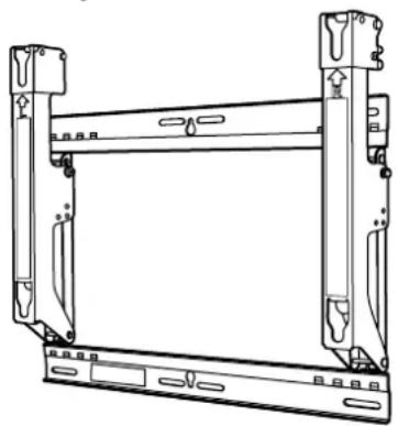
TY-WK5P1RW Wall-hanging bracket (Adjustable angle type) Parts used to assemble the wall-hanging bracket
Parts used for installation
View of fully assembled fixtur
natural_image
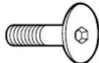
Technical line drawing of a mechanical frame assembly (no text or symbols)A M8×32 Allen head countersunk screws (4)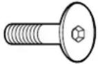 | D Spacers (4) |
B Dished toothed washers (4) E | M5x50 Screw for securing unit (2)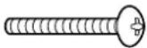 |
C Insulation spacers (4) | F Allen wrench (included tool) (1) |
Precautions for wall-hanging bracket fitting
The wall-hanging bracket is for use in attaching a plasma TV unit to a vertical wall for viewing. Do not fit to any surface other than a vertical wall.
◆ To ensure correct plasma TV performance and prevent trouble, do not fit at any of the following locations.
- Near sprinklers or fire/smoke detectors
- Where there is a risk of exposure to vibration or impact
- Near high-voltage wires or dynamic power supplies
- Near sources of magnetism, heat, water vapor or soot
- Locations exposed to air blown from heating equipment
- Where droplets of condensation from an air conditioner or other unit may form
◆ Fit using techniques suited to the structure and materials of the fitting location.
Use commercially available screws with a nominal diameter of 6 mm (0.2 inches) that are suited to the wall material (wood, steel frame, concrete etc.) you are fitting the bracket to.
◆ For the TV power supply plug, use a power supply outlet that can be reached easily.
◆ Ensure good air flow so that the equipment ambient temperature does not exceed 40 °C (104 °F). Failure to do this may cause heat to build up inside the plasma TV, resulting in malfunction.
◆ Spread a soft blanket or cloth over the floor so that the plasma TV and floor will not be marked or scratched during the assembly and installation work.
When screwing down the parts, ensure that the screws are neither insufficiently tightened nor over tightened.
Take sufficient care to ensure safety around you when performing the assembly and installation work or while moving about during the course of the work.
Do not install the Plasma TV underneath ceiling lamps (spotlights, halogen lamps, etc.). Otherwise, the cabinet may be bent or damaged by high heat.
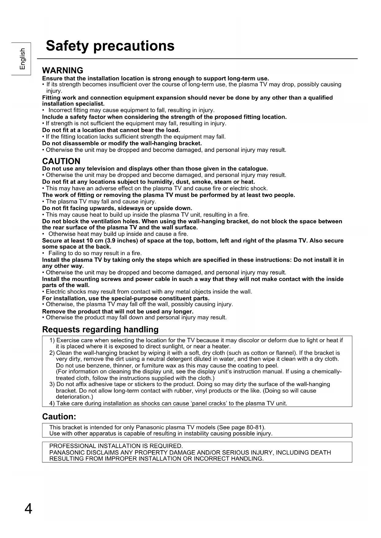
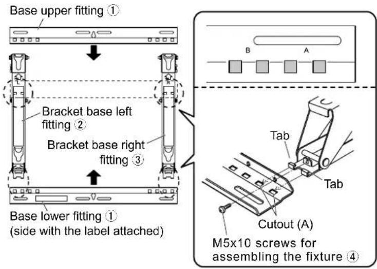
1. Assembling the wall-hanging bracket
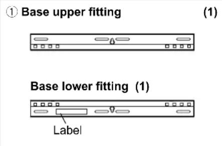
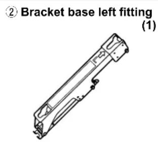
Lay the base upper and lower fittings ① and the bracket base left and right fittings ② and ③ as shown in the figure.
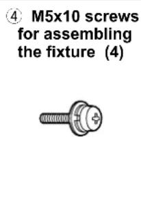
Fit the protrusions (tabs) of the bracket base left and right fittings into the cutouts (2 on the left and 2 on the right) in the base upper and lower fittings, and secure the parts using the four screws ④ for assembling the fixture.
(Tightening torque: 1.2 to 1.5 N·m)
Note
- Please hold the bracket base left and right fittings as you work with the assembled wall hanging bracket. Holding the base upper and lower fittings might deform this unit.
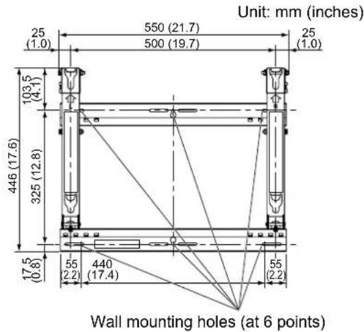
2. Checking the strength of the installation location
① The wall-hanging bracket weighs approximately 3.2 kg (7.1 lbs).
Refer to the instruction manual of the plasma TV, and check the weight of the plasma TV unit which will be fitted into the wall-hanging bracket.
② Refer to the outline drawing of the wall-hanging bracket shown on the right, and check the wall strength at the six installation positions shown. If the strength at any of these positions is lacking, provide sufficient reinforcement.
Notes
- There are five pre-drilled mounting holes at the top and another five at the bottom of the wall-hanging bracket.
Use the spare holes provided if wood or some other material is used for the wall and a sufficient level of mounting strength cannot be ensured by anchoring the fixture at the six positions shown on the right.
However, bear in mind that, depending on which materials the mounting surface is made of, cracks may form on the surface if the screws are used at positions which are too close together. - Mount or place only a plasma TV on the fixture: Do not mount or place any other product.
- For details on the dimensions applying when the plasma TV is mounted, refer to the outline drawing (on page 80-81).
- Mount or place only a plasma TV on the fixture: Do not mount or place any other product.
- For details on the dimensions applying when the plasma TV is mounted, refer to the outline drawing (on page 80-81).
Use the screws without fail to anchor the fixture.
3. Installing the wall-hanging bracket on the wall
Notes
- If it is necessary to embed screws or nuts in the wall prior to installing the wall-hanging bracket because the wall is made of concrete or such other materials, determine the positions of the holes by fitting the actual wall-hanging bracket or calculating from the figures shown in the outline drawing, and then embed screws or nuts with a nominal diameter of 6 mm (0.2 inches) or their equivalent.
If you are embedding the screws, make sure they protrude from the wall surface by 10 to 15 mm (0.4 to 0.6 inches). - For installing the wall-hanging bracket onto the wall, use screws with a nominal diameter of 6 mm (0.2 inches) or their equivalent available from a hardware store and suited to the materials of the installation area on the wall.
- Anchor the screws in at least six locations.
① Install the wall-hanging bracket so that the arrows indicated on it are pointing upward.
② First of all, secure the screw in the upper center hole A.
③ Use a level to ensure that the bracket is not inclined at an angle, and screw the bracket into position using the three screw holes at the bottom.
④ Remove the angle adjustment screws from the bracket base left and right fittings ② and ③, and open the bracket base left and right fittings ② and ③.
⑤ Screw the bracket into position using the screws at the remaining two screw holes at the top.
⑥ Use the angle adjustment screws, which were removed, to perform the angle adjustment of step 4.
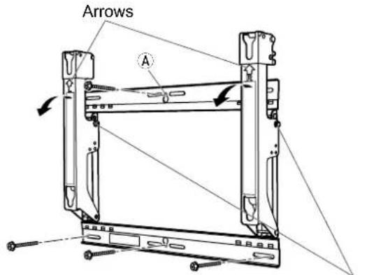
Angle adjustment screws
natural_image
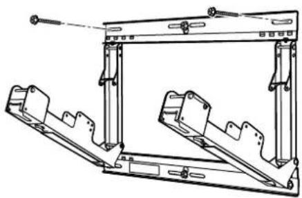
Technical line drawing of a mechanical frame assembly (no text or symbols)4. Adjusting the angle of the wall-hanging bracket
① The angle of this wall-hanging bracket can be adjusted in 5-degree increments to one of five positions ranging from "Zero tilting" to "20-degree tilting". The wall-hanging bracket is shipped from the manufacturing plant in the "Zero tilting" angle position. To change the angle, use the angle adjustment screws to change the position of the stay.
(Tightening torque: 1.2 to 1.5 N·m)
Note
- When using some types of HDMI cables or PC cables, the cable may touch the wall and cause damage to the HDMI terminal or the PC input terminal on the television set.
In such a case, adjust the angle of the wall-hanging bracket so that no weight is applied to the cable.
Fitting procedure
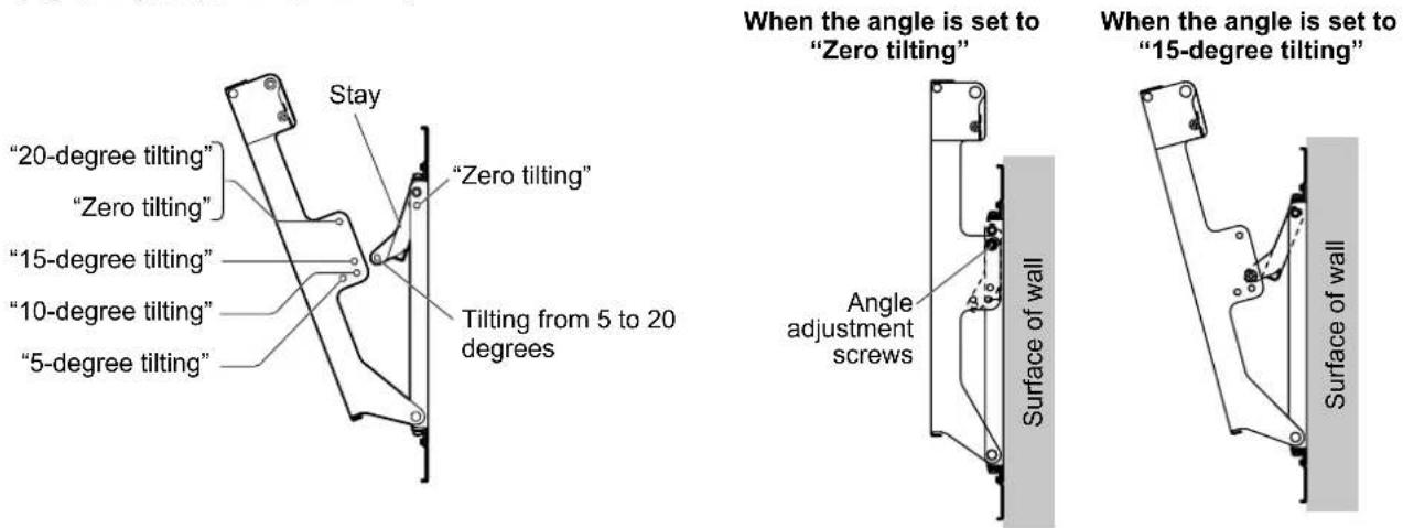
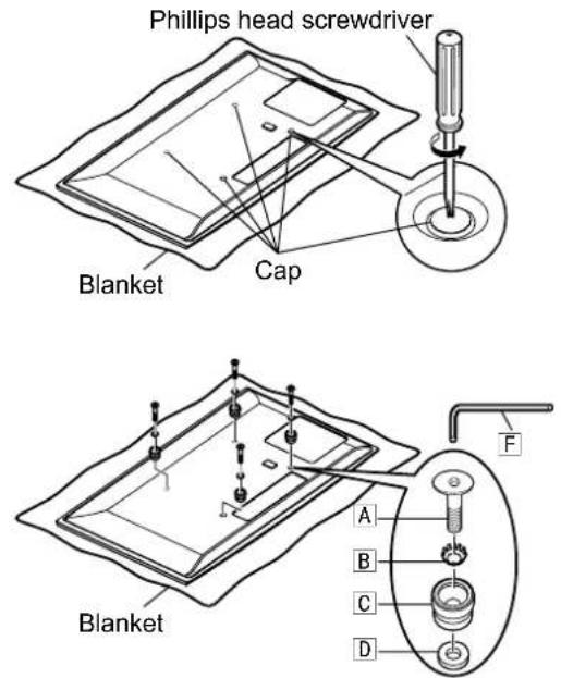
5. Installing the insulation spacers onto the plasma TV
① Place the plasma TV face down on a clean blanket or other piece of fabric free from dirt and foreign matter, and proceed as instructed below.
Take care to prevent scratches or damage if the plasma TV has protruding parts.
② Use a Phillips head screwdriver to remove the caps (4) from the plasma TV.
Note
- Keep the caps which have been removed in a safe place. (They will be required when a separate installation stand is used.)
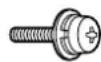
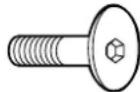
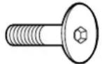
③ As shown in the figure on the right, install the accessory M8×32 Allen head countersunk screws A, dished toothed washers B, insulation spacers C and spacers D (x4 for each part) using included allen wrench F at the locations where the caps were previously installed.
(Tightening torque: 3 to 4 N·m)
* Appearance of the plasma TV differs according to the model. The figure below is an example of an applicable model.
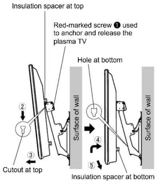
6. Mounting the plasma TV onto the wall-hanging bracket and connecting it to the other components
① Remove the left and right red-marked screws ① (one at the left and one at the right) used to anchor and release the plasma TV.
② Fit the insulation spacers at the top of the plasma TV onto the cutouts at the top of the wall-hanging bracket, and lower the plasma TV.
③ Pull the plasma TV toward you as shown in the figure on the right, and connect it to the other components.
④ After completing the connections, lift the plasma TV slightly, and insert the insulation spacers at the bottom into the holes at the lower part of the wall-hanging bracket.
⑤ Now lower the plasma TV.
CAUTION
- If the plasma TV is lifted too much, its top part will become disengaged from the wall-hanging bracket.
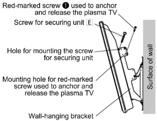
7. Anchoring the plasma TV
① Install the accessory screws for securing unit E (2) into the mounting holes of the screws for securing unit on the sides (left and right) of the wall-hanging bracket.
② Securely tighten the left and right red-marked screws ① (one at the left and one at the right) used to anchor and release the plasma TV in the red-marked screw mounting holes on the side of the wall-hanging bracket used to anchor and release the plasma TV.
(Tightening torque: 1.2 to 1.5 N·m)
Note
- In order to prevent the plasma TV from becoming disengaged from the wall-hanging bracket, the screws for securing unit E must be securely tightened at the left and right as far as their bases.
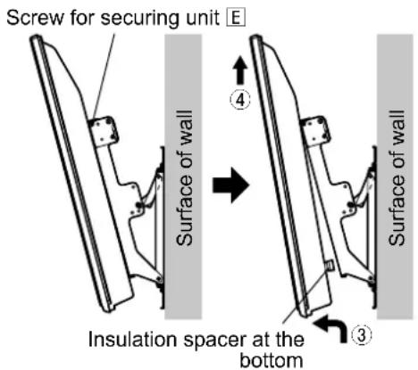
How to remove the plasma TV from the wall-hanging bracket
① Remove the screws for securing unit for the display E (one at the left and one at the right) which are mounted on the sides of the wall-hanging bracket.
② Disconnect the wires connecting the plasma TV to the other units.
③ While lifting the bottom part of the plasma TV, pull the plasma TV toward you.
④ Once the insulation spacers at the bottom have been released, lift the plasma TV straight up.
Warnung
natural_image
Technical line drawing of a mechanical frame assembly (no text or symbols)natural_image
Technical line drawing of a mechanical frame assembly (no text or symbols)natural_image
Technical line drawing of a mechanical component (no text or symbols)(1)
③ Rechtersteunprofiel (1)
natural_image
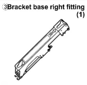
Technical line drawing of a mechanical component (no text or symbols)④ M5x10-
steunmontageschroeven
(4)
natural_image
Technical line drawing of a mechanical frame assembly (no text or symbols)A M8×32-inbusbouten met plat verzonken kop (4)
D Ringetjes (4)

B Getande veerklemmen
(4) E
natural_image
Technical line drawing of a mechanical frame assembly (no text or symbols)4. De hoek van de muurbevestigingssteun instellen
natural_image
Technical line drawing of a mechanical frame assembly (no text or symbols)natural_image
Technical line drawing of a mechanical frame assembly (no text or symbols)natural_image
Technical line drawing of a mechanical frame assembly (no text or symbols)natural_image
Technical line drawing of a mechanical frame assembly (no text or symbols)natural_image
Technical line drawing of a mechanical frame assembly (no text or symbols)A Tornillos Allen M8×32 de cabeza avellanada (4)
D Espaciadores (4)

B Arandelas dentadas convexas (4)

natural_image
Technical line drawing of a mechanical frame assembly (no text or symbols)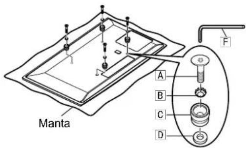
natural_image
Technical line drawing of a mechanical component with no visible text or symbolsnatural_image
Technical line drawing of a mechanical component (no text or symbols)natural_image
Technical line drawing of a mechanical frame assembly (no text or symbols)A Parafusos Allen M8×32 de cabeça de embeber (4)
natural_image
Technical line drawing of a mechanical assembly with brackets and mounting holes (no text or symbols)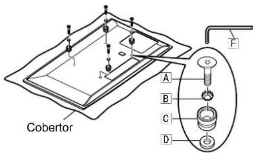
natural_image
Technical line drawing of a mechanical component (no text or symbols)natural_image
Technical line drawing of a mechanical component (no text or symbols)natural_image
Technical line drawing of a mechanical frame assembly (no text or symbols)natural_image
Technical line drawing of a mechanical frame assembly (no text or symbols)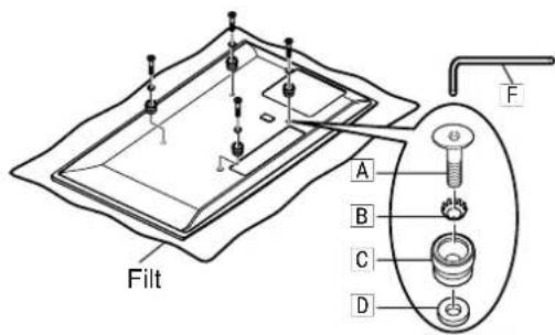
natural_image
Technical line drawing of a mechanical component (no text or symbols)(1)
natural_image
Technical line drawing of a mechanical component with no visible text or symbols(1)
natural_image
Technical line drawing of a mechanical frame assembly (no text or symbols)natural_image
Technical line drawing of a mechanical frame assembly (no text or symbols)natural_image
Technical line drawing of a mechanical component or bracket (no text or symbols)natural_image
Technical line drawing of a mechanical component (no text or symbols)natural_image
Technical line drawing of a mechanical frame assembly (no text or symbols)natural_image
Technical line drawing of a mechanical frame assembly (no text or symbols)natural_image
Pure mechanical assembly diagram without any text, numbers, or symbolsПоверхокотб стены
natural_image
Technical line drawing of a mechanical frame assembly (no text or symbols)natural_image
Technical line drawing of a mechanical frame assembly (no text or symbols)natural_image
Technical line drawing of a mechanical component with no visible text or symbolsnatural_image
Technical line drawing of a mechanical component or bracket (no text or symbols)(1)
natural_image
Technical line drawing of a mechanical frame assembly (no text or symbols)natural_image
Technical line drawing of a mechanical frame assembly (no text or symbols)natural_image
Technical line drawing of a mechanical frame assembly (no text or symbols)natural_image
Technical line drawing of a mechanical frame assembly (no text or symbols)4. 调整壁挂式框架的角度
natural_image
Technical line drawing of a mechanical frame assembly (no text or symbols)natural_image
Technical line drawing of a mechanical frame assembly (no text or symbols)Wall-hanging bracket (Adjustable angle type) External dimensions drawing
(Unit : mm (inches))
(Einheit: mm)
(Eenheid: mm)
(Unità: mm)
(Unité : mm)
(Unidad: mm)
(Unidade : mm)
(Enhet: mm)
(Enhed: mm)
(Единицы: мм)
Wall-hanging bracket (Adjustable angle type)
External dimensions drawing
(Unit : mm (inches))
(Einheit: mm)
(Eenheid: mm)
(Unità: mm)
(Unité : mm)
(Unidad: mm)
(Unidade : mm)
(Enhet: mm)
(Enhed: mm)
(Единицы: мм)