
Vector 75 - Tripod Vinten - Free user manual and instructions
Find the device manual for free Vector 75 Vinten in PDF.
User questions about Vector 75 Vinten
0 question about this device. Answer the ones you know or ask your own.
Ask a new question about this device
Download the instructions for your Tripod in PDF format for free! Find your manual Vector 75 - Vinten and take your electronic device back in hand. On this page are published all the documents necessary for the use of your device. Vector 75 by Vinten.
USER MANUAL Vector 75 Vinten
Vector 75 Pan and Tilt Head
V4095-0001
natural_image
Technical line drawing of a mechanical device with labeled components (no readable text or symbols)Operators Guide
V4095-4980/2
Vinten
Vector 75
Pan and Tilt Head
Publication Part No. V4095-4980 Issue 2
English ...... Page 3
Copyright © 2011 The Vitec Group plc
All rights reserved throughout the world. No part of this document may be stored in a retrieval system, transmitted, copied or reproduced in any way, including, but not limited to, photocopy, photograph, magnetic or other record without the prior agreement and permission in writing of the Vitec Group plc.
Trademarks
Vinten ^™ , Vector ^® and Quickfix ^® are registered trademarks of the Vitec Group plc.
Disclaimer
Information contained within this document is subject to change. Camera Dynamics Limited reserves the right, without notice, to make changes in equipment design or performance as progress in engineering, manufacturing or technology may warrant.
Published by
Vitec Group Videocom Division Technical Publications Department William Vinten Building Western Way Bury St Edmunds Suffolk IP33 3TB United Kingdom Email: technical.publications@vitecgroup.com
Contents
Page
Safety – read this first .... 4
Warning symbols in this Operators Guide 4
Usage....4
Caring for the environment by recycling 4
Technical specification .... 5
Introduction and description....7
Perfect Balance 7
Pan and tilt drag....7
Pan and tilt brakes....7
Illuminated level bubble 7
Pan bar 7
Camera mounting 7
Operation 8
Unpacking 8
Mounting the head 8
Pan bars....8
Fitting a camera....9
Balancing the head 9
Locking the platform.... 11
Pan and tilt brakes.... 11
Pan and tilt drag.... 11
Maintenance 12
General 12
Cleaning....12
Cleaning balance mechanism tracks....12
Routine maintenance....13
Replacing the battery....13
Adjustments....14
Adjusting the slide plate clamp 14
Repositioning the wedge adaptor 14
Adjusting the pan and tilt brakes 15
Parts list ....16
Safety – read this first
Warning symbols in this Operators Guide

WARNING
Where there is a risk of personal injury or injury to others, comments appear highlighted by the word ‘WARNING’—supported by the warning triangle symbol.
Where there is a risk of damage to the product, associated equipment, process or surroundings, comments appear highlighted by the word 'CAUTION'.

FINGER TRAP
Where there is a risk of trapping fingers within parts of the product or other equipment mounted to the product, comments appear supported by the finger trap symbol.
Usage
The Vector 75 pan and tilt head is designed for use in broadcast and film studios to support and balance a camera and ancillary equipment weighing up to 75 kg (165.3 lb), and must be mounted on equipment designed to support a minimum payload of 95 kg (209 lb).
The Vector 75 pan and tilt head is intended for use by professional TV broadcast and film camera operators.

WARNING!
- Do NOT attempt to use this product if you do not fully understand how to operate it.
- Do NOT use this product for any other purpose than that specified in the Usage statement.
- Refer all maintenance beyond that detailed in this Operators Guide to an authorised Vinten service centre.
Caring for the environment by recycling
Disposal of waste batteries
Any batteries included with this product must not be treated as household waste. By ensuring these batteries are disposed of correctly, you will help prevent potentially negative consequences for the environment and human health, and help conserve natural resources. Hand the battery over to the applicable collection point for recycling waste batteries.
Technical specification
Maximum payload 75 kg (165.3 lb)
Payload Centre of Gravity height range 80–250 mm (3–10 in.)
Weight (complete with pan bar and wedge adaptor)....19.15 kg (42.2 lb)
Overall dimensions:
Height (with wedge adaptor)
Minimum balance setting . . . . . . . . . . . . . . . . . . . . . . . . . . . . . . . . . . . . . . . . . . . . . . . . . . . . . . . . . . 255 mm (10.0 in.)
Maximum balance setting....355 mm (14.0 in.)
Length (without pan bar) ....355 mm (14.0 in.)
Width (without pan bar) .....350 mm (13.8 in.)
Width (with two pan bars)....445 mm (17.5 in.)
Tilt range. ±52^
Pan range....360°
Counterbalance .... fully variable Perfect Balance system
Level bubble.... illuminated, high contrast blue LED
Level bubble illumination 15 seconds (timeout)
Battery....PP3 (9V)
Tripod fixing .... Four-bolt flat base with Quickfix ^® groove (standard)
Vector 75
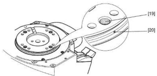
Pan and Tilt Head, left side
(Fig. 1)
[1]......Wedge adaptor
[2] Wedge adaptor lever
[3] Wedge adaptor securing screw
[4] Pan brake lever
[5] Tilt brake lever
[6] Carrying handle
[7]Level bubble illumination switch
[8]Level bubble
[9] Pan drag adjustment knob
[10] Pan bar clamp
[11]....Tilt drag adjustment knob
[12] ...... Slide plate clamp
[13] ...... Slide plate adjustment knob (retractable 'T' bar)
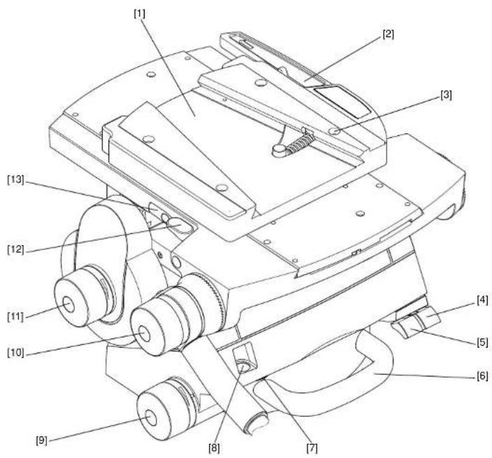
Vector 75 Pan and Tilt Head, right side (Fig. 2)
[14] Slide plate
[15] Perfect Balance adjustment knob
[16] Centre lock button
[17]....Centre lock release catch
[18] Pan bar mount
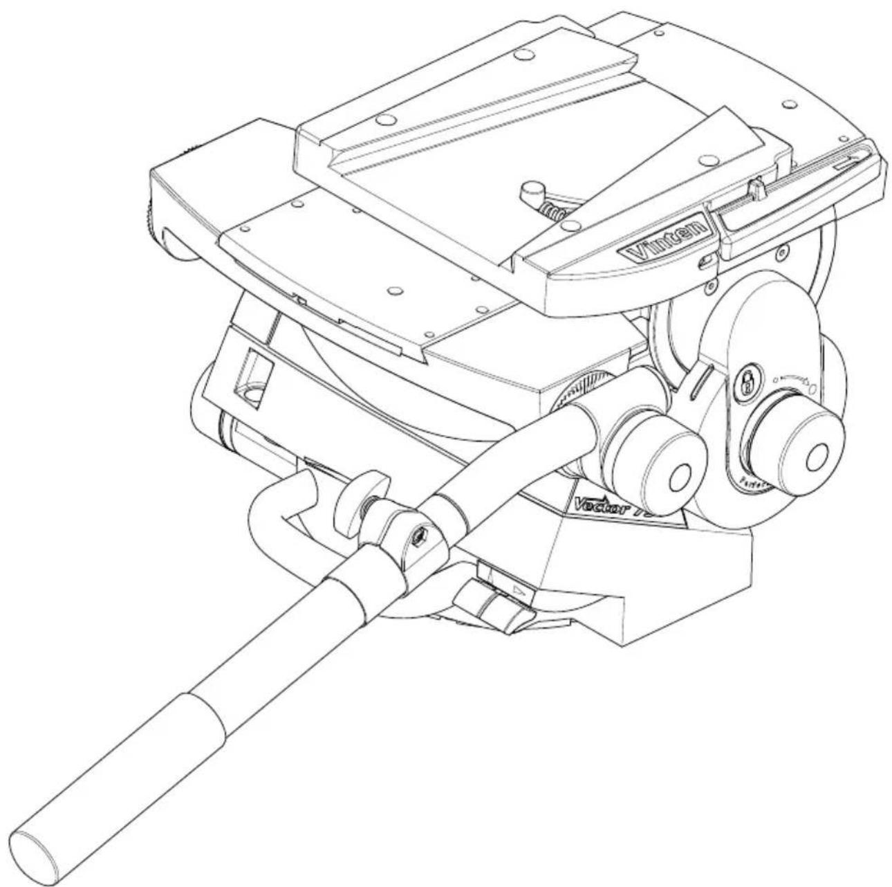
Vector 75 Pan and Tilt Head, underside (Fig. 3)
[19] . . . . . . . . . . . . . . . . . . . . . . . . . . . . . . . . . . . . . . . . . . . . . . . . . . . . . . . . . . . . . . . . . . . . . . . . . . . . . . . . . . . Bolt fixing hole
[20]Bolt-hole position indicator
Introduction and description
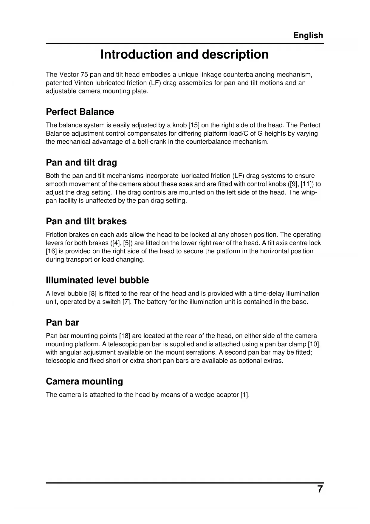
The Vector 75 pan and tilt head embodies a unique linkage counterbalancing mechanism, patented Vinten lubricated friction (LF) drag assemblies for pan and tilt motions and an adjustable camera mounting plate.
Perfect Balance
The balance system is easily adjusted by a knob [15] on the right side of the head. The Perfect Balance adjustment control compensates for differing platform load/C of G heights by varying the mechanical advantage of a bell-crank in the counterbalance mechanism.
Pan and tilt drag
Both the pan and tilt mechanisms incorporate lubricated friction (LF) drag systems to ensure smooth movement of the camera about these axes and are fitted with control knobs ([9], [11]) to adjust the drag setting. The drag controls are mounted on the left side of the head. The whip-pan facility is unaffected by the pan drag setting.
Pan and tilt brakes
Friction brakes on each axis allow the head to be locked at any chosen position. The operating levers for both brakes ([4], [5]) are fitted on the lower right rear of the head. A tilt axis centre lock [16] is provided on the right side of the head to secure the platform in the horizontal position during transport or load changing.
Illuminated level bubble
A level bubble [8] is fitted to the rear of the head and is provided with a time-delay illumination unit, operated by a switch [7]. The battery for the illumination unit is contained in the base.
Pan bar
Pan bar mounting points [18] are located at the rear of the head, on either side of the camera mounting platform. A telescopic pan bar is supplied and is attached using a pan bar clamp [10], with angular adjustment available on the mount serrations. A second pan bar may be fitted; telescopic and fixed short or extra short pan bars are available as optional extras.
Camera mounting
The camera is attached to the head by means of a wedge adaptor [1].
Operation
Unpacking
The head is supplied with a telescopic pan bar, automatic wedge adaptor and a battery (already fitted) for the level bubble illumination unit.
A second telescopic or fixed short or extra short pan bar for use with a zoom or focus controller is optional. Ensure that all items are unpacked prior to disposal of the packing materials.
After unpacking ensure that:
The pan and tilt brakes ([4], [5]) are on (see Pan and tilt brakes on page 11).
The centre lock [16] is engaged (see Locking the platform on page 11). Always engage the centre lock before lifting or carrying the head.
CAUTION! Do NOT lift the head by the platform. Only use the base and/or the carrying handle to prevent damaging the head.
Mounting the head
NOTE: When mounted on Vinten 'Hawk' or 'Teal' pedestals, clearance between the head and the pedestal weight tray prevents the use of 1.6 kg (5.5 lb) and 0.5 kg (1.0 lb) trim weights. Use alternative weights or fit the adaptor plate kit (part no. 3354-900SP) between the head and pedestal.

WARNING!
- Only mount this product on equipment designed to support a minimum of 95 kg (109 lb).
- Before installing the head, hold a fixing bolt in position and check that the threaded end does not project more than 20 mm (3/4 in.) above the mounting face.
The head is mounted on a tripod, pedestal or suitable firm surface using the four fixing bolts and washers. The four bolt-fixing holes [19] on the underside of the head are easily located using the bolt-hole position indicators [20] . Tighten the bolts with the spanner provided.
After mounting the head, ensure it is level using the level bubble [8], which may be illuminated by pressing the switch [7]. The light will go out after 15 seconds (timeout function).
Pan bars
Fit the pan bars to the head and adjust the position of each one before tightening the clamp [10] on the mounting [18]. Adjust the length of the telescopic pan bar(s).
Fitting a camera

WARNING!
- Do NOT rely on the tilt brake when changing the payload. Always engage the centre lock.
- Ensure that the weight and C of G height of the total payload is within the range for which the head is designed: up to 75 kg (165.3 lb) with a C of G height of 80–250 mm (3–10 in).
To fit a camera, proceed as follows:
Lower the mounting to a convenient working height.
If not already fitted, install the wedge adaptor [1] in the middle position on the slide plate [14] (see Repositioning the wedge adaptor on page 14).
Attach the wedge to the camera/lens.
Ensure that the centre lock [16] is engaged (see Locking the platform on page 11).
Apply the pan brake [4] (see Pan and tilt brakes on page 11).
Slide the wedge adaptor lever [2] forward (parallel to the wedge) about 6 mm (1/4 in.) against spring tension. Pull the lever out, away from the body of the wedge adaptor, as far as it will go.
Insert the camera wedge into the wedge adaptor [1] and push it forward until it is fully engaged. Push in the wedge adaptor lever [2] , until it lies parallel with the wedge adaptor body. During this operation the resistance of the spring-loaded over-centre mechanism will be felt. As the lever reaches the end of its travel, it will snap into the locked position (indicated by the closed padlock symbol above the lever).

Confirm that the lever is locked by briefly pulling it outward, away from the wedge adaptor body. If the lever is locked, it should not move and the closed padlock symbol only should be visible.
Install the remainder of the payload (e.g. lens, zoom and focus controls, viewfinder, prompter etc.).
Balancing the head
NOTE: It is important that the pan bar(s) and all camera accessories (lens, zoom and focus controls, viewfinder, prompter etc.) are fitted in their operational position before balancing the head.
Any equipment fitted or adjusted later will unbalance the head.
Balancing the head consists of positioning the payload fore and aft on the head so that its C of G is immediately above the platform pivot, then compensating for the payload C of G height using the Perfect Balance adjustment knob.
Position the payload fore and aft as follows:
Ensure that the centre lock is engaged (see Locking the platform on page 11) and that the camera and all accessories are fitted.
Turn the tilt drag adjustment knob [11] to its minimum setting.

WARNING!
Increase the balance setting for a heavy, out-of-balance payload BEFORE disengaging the centre lock, to prevent the platform tipping violently.
Holding the pan bar to steady the platform, press down the release catch [17] to disengage the centre lock (see Locking the platform on page 11).
Push the clamp lever [12] downward to release the slide plate clamp and pull out the slide plate adjustment knob or 'T' bar [13] until it engages with the platform drive. Turn the 'T' bar to move the slide plate fore and aft to achieve horizontal balance.
The horizontal balance is correct when no perceptible tilting force can be felt on the pan bar with the platform level. Apply the slide plate clamp [12] by pulling the clamp lever upward.
If there is insufficient movement in the slide plate to achieve balance, reposition the wedge adaptor (see Maintenance on page 12), refit the load and repeat the horizontal balancing procedure.
When fore and aft balance has been achieved, adjust the payload C of G height as follows:

WARNING!
Keep a firm grip on the pan bar to steady the camera payload. Be prepared to prevent the head falling away suddenly.
Using the pan bar, tilt the platform forward and backward. When correctly balanced, there should be no perceptible tilting force on the pan bar at any angle of tilt and the head should remain in any tilt position to which it is set.
If the head tends to fall away when the platform is tilted, push and turn the Perfect Balance adjustment knob [15] clockwise to increase the C of G height setting. If the head tends to spring back to centre, push and turn the Perfect Balance adjustment knob [15] counter-clockwise to decrease the C of G height setting.
NOTE: The Perfect Balance adjustment knob is a multi-turn control. To enable the knob to be turned more easily, slightly tilt the platform using the pan bar whilst turning the knob.
When the payload C of G height adjustment is complete, check that the fore and aft balance remains satisfactory. Readjust the position of the slide plate if necessary.
After balancing, release the brakes and exercise the head through both axes to confirm that it operates smoothly.
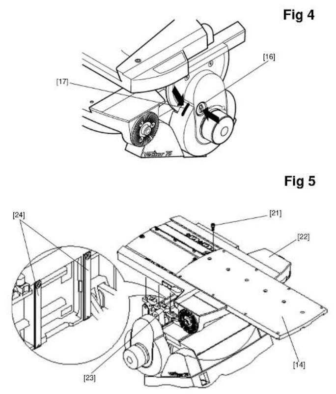
Locking the platform
(Fig 4)
The centre lock mechanism is operated by a button [16] on the right side of the head. To engage the lock, hold the platform in the horizontal position and push the button [16] inwards, until it latches and the release catch [17] appears. Use the pan bar to rock the platform slightly whilst pushing the button [16] .
To release the centre lock, rock the platform slightly and push down on the release catch [17].

text_image
CAUTION finger trapWARNING! FINGER TRAP
Keep fingers clear of the platform underside when tilting to avoid personal injury.
Pan and tilt brakes
The pan and tilt brakes are operated by levers ([4], [5]) at the rear of the head. They are applied by pulling the appropriate lever up and back and released by pushing the lever forwards.
CAUTION!
- Do NOT use force on the brake levers. Hand tighten only.
- Do NOT use the brakes to supplement drag, the head may be damaged. When the brakes are not in use, always ensure they are fully released.
The brakes should be applied whenever the camera is left unattended.
Pan and tilt drag
The pan drag adjustment knob [9] is mounted on the left lower part of the main body. Tilt drag is adjusted by a knob [11] mounted on the face of the tilt drag housing on the left side of the head.
Turn the knobs clockwise to increase drag and counter-clockwise to decrease drag.
CAUTION! Reduce drag to a minimum when the head is out of use for long periods, to minimise wear on drag components.
Maintenance
General
The Vector 75 pan and tilt head is robustly made to high engineering standards and little attention is required to maintain serviceability except regular cleaning. Adjustments and repairs should be carried out only by a competent person.
Cleaning
During normal use the only cleaning required should be a regular wipe over with a lint-free cloth. Dirt accumulated during storage or periods of disuse may be removed with a vacuum cleaner. Particular attention should be paid to the wedge location faces of the wedge adaptor.
CAUTION! DO NOT use solvent- or oil-based cleaners, abrasives or wire brushes to remove accumulations of dirt as these damage the protective surfaces. To clean mechanical surfaces, use only detergent-based cleaners.
Use out-of-doors under adverse conditions may require special attention, and the head should be covered when not in use. Salt spray should be washed off using fresh water at the earliest opportunity. Sand and dirt act as an abrasive and should be removed using a vacuum cleaner or a supply of clean, dry air.
Cleaning balance mechanism tracks
The balance mechanism tracks are automatically cleaned by built-in wipers, but after use in particularly adverse conditions the tracks may require cleaning. Some dismantling of the head is necessary and it is recommended that this be carried out in clean workshop conditions.
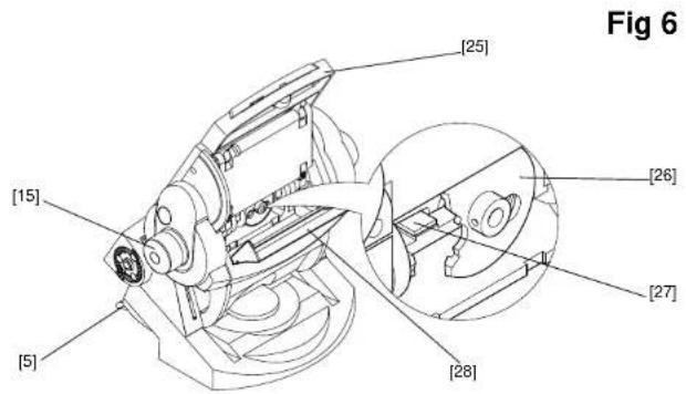
Vertical tracks (Fig 5)
To clean the vertical tracks it is necessary to remove the platform; proceed as follows:
Remove the payload (if fitted). It is not necessary to remove the wedge adaptor.
Release the slide plate clamp [12]. Use the adjustment knob [13] to wind the slide plate [14] backwards until it is clear of fixing screws [21].
Level the platform.
Remove six screws [21] securing the platform [22] to the balance mechanism [23]. Lift off the platform.
Using a pipe cleaner (or similar) moistened with an isopropanol-based cleaner (3M VBH or similar) clean the two vertical tracks [24] . Upwards pressure on the balance mechanism will allow the area of track under the vertical rollers to be cleaned.
Install the platform [22] on the balance mechanism [23] and secure with six screws [21] using Loctite 222E.
Using the adjustment knob [13] wind the slide plate forwards to the central position.
Refit the payload (if required) and rebalance the head.
Horizontal tracks (Fig 6)
No dismantling is necessary to clean the horizontal tracks; proceed as follows:
Remove the payload (if fitted).
Set the balance mechanism to its maximum setting by pushing in the Perfect Balance knob [15] and turning it clockwise to its stop.
Tilt the platform fully backwards and apply the tilt brake [5].
Pull down the flap guard [28] to reveal the bevel gear [26]. Access to the horizontal tracks [27] is through the holes in the bevel gear, which may be rotated freely.
Using a pipe cleaner (or similar) moistened with an isopropanol-based cleaner (3M VBH or sim.), clean the two horizontal tracks. Upwards pressure on the balance mechanism will allow the area of track under the horizontal rollers to be cleaned.
Release the flap guard [28] and the tilt brake [5] and return the platform to the horizontal position.
Refit the payload (if required).
Routine maintenance
Routine maintenance on the Vector 75 pan and tilt head is limited to annual replacement of the level bubble illumination battery.
During normal use, check the effectiveness of the platform slide clamp and the adequacy of level bubble illumination.
No further routine maintenance is required.
Replacing the battery
(Fig 7)
The level bubble on the Vector 75 pan and tilt head is illuminated by a battery-powered LED. A time-delay circuit initiated by a switch controls the LED. The battery should be replaced at yearly intervals or whenever the illumination is considered inadequate.
NOTE: Dependent on the type of mounting, it may be necessary to remove the head from the mounting for access to the battery compartment.
To install or replace the battery proceed as follows:
Remove three screws [29] which secure the battery compartment cover plate [32].
Install the battery [30] by pushing the connector [31] onto the battery terminals.
Position the battery in the battery compartment, ensuring that the wiring is not trapped.
Refit the battery compartment cover plate [32], ensuring battery locates in cover plate. Secure with three screws [29].
Press the switch [7] and ensure the LED is lit for approximately 15 seconds.
Adjustments
After considerable use the slide plate clamp may require adjustment.
To enable the payload to be correctly balanced, the wedge adaptor may require repositioning.
The pan and tilt brakes may require adjustment after considerable use.
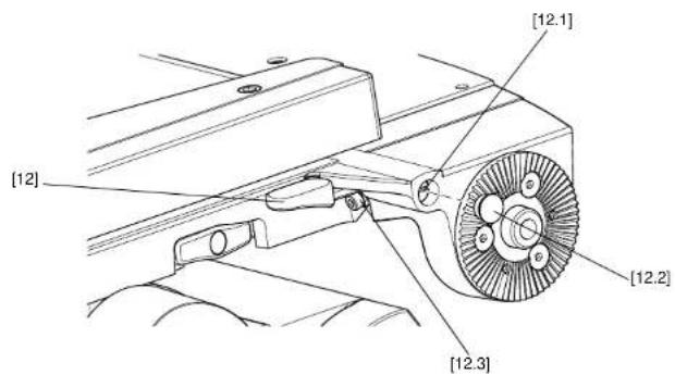
Adjusting the slide plate clamp
(Fig 8)
The slide plate clamp [12] should be set so that in the up or clamped position it prevents the slide plate from being moved, while in the down or released position it allows free adjustment of the slide plate. To adjust the clamp, proceed as follows:
On the left-hand side of the platform, carefully remove the plastic cap [12.2] to reveal the slotted shaft [12.1] .
Pull the slide plate clamp lever [12] fully upwards.
Slacken the clamp screw [12.3].
Turn the slotted shaft [12.1] fully clockwise to apply the clamp.
Tighten the clamp screw [12.3].
Move the lever over its full range and ensure that in the clamped position it prevents the slide from being moved, while in the released position it allows free adjustment of the slide. Readjust if necessary.
Replace the plastic cap [12.2] over the slotted shaft [12.1].
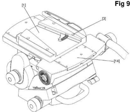
Repositioning the wedge adaptor
(Fig 9)
The wedge adaptor [1] is secured by four cap head screws [3] which pass through the wedge adaptor into the slide plate [14].

WARNING!
Overlong screws will prevent the slide plate from operating. Always use the screws provided (M6 x 30 mm).
To reposition the wedge adaptor:
Engage the centre lock (see Locking the platform on page 11) and remove the load.
Hold the body of the wedge adaptor [1] and use a 4 mm hexagon wrench to remove four securing screws [3].
Reposition the wedge adaptor [1] on the slide plate [14], ensuring that the narrow end of the wedge adaptor faces forwards.
Insert the four screws [3] in the holes in the wedge adaptor and tighten.
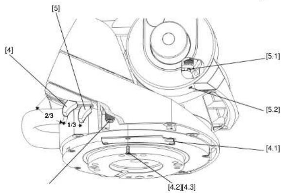
Adjusting the pan and tilt brakes
(Fig 10)
The pan and tilt brakes should be set so that the brakes begin to be applied after approximately one-third of the lever travel. The tilt brake is adjusted by inserting a 2 mm hexagon wrench through the hole [5.2] in the bottom of the tilt unit cover and turning the grub screw [5.1] .
To adjust the tilt brake, proceed as follows:
Operate the tilt brake lever [5] from the OFF to the ON position.
If brake pressure is not felt after approximately 1/3 of lever travel, turn the grub screw [5.1] clockwise until this is achieved.
Operate the tilt brake lever [5] to the OFF position and ensure that the platform is free to move.
The pan brake is adjusted by turning the pin [4.3] . To gain access to the pin it is necessary to remove the payload from the head, remove the head from its mounting and remove a cover plate [4.1] from the underside of the head.
To adjust the pan brake, proceed as follows:

WARNING!
Remove the payload before adjusting the pan brake.
Remove the payload from the head.
Remove the head from its mounting.
On the underside of the head, remove three screws [4.2] securing the cover plate [4.1] .
Operate the pan brake lever [4] from the OFF to the ON position.
If brake pressure is not felt after approximately 1/3 of the lever travel, turn the pin [4.3] clockwise until this is achieved.
Set the pan brake lever [4] to the OFF position and ensure that the head is free to rotate.
Refit the cover plate [4.1] and secure with three screws [4.2].
Parts list
The following list includes main assemblies, user-replaceable spare parts and optional accessories. For further information regarding repair or spare parts, please contact Vinten or your local Vinten distributor. For more information visit our website at www.vinten.com.
Main assemblies
Vector 75 pan and tilt head. V4095-0001
Telescopic pan bar and clamp assembly 3219-82
Automatic wedge adaptor.... 3460-3
Fixing bolts (4 off)....L054-714
Washers (4 off, for fixing bolts).... L602-122
Spanner (for head bolts).... J551-001
Battery (9V, PP3) C550-023
User-replaceable spare parts
Level bubble illumination unit battery - 9V, 6LR61
(PP3, 6AM6, MN1604, E-BLOCK or equivalent) C550-023
Vinten Flat-Base Head-Fixing Kit (SP)....V4095-1902
Optional accessories
Lightweight Mitchell adaptor.... 3103-3
Heavy-duty Mitchell adaptor for Vinten pedestal
mounting in conjunction with Hi-hat Adaptor, part no. 3055-3 ..... 3724-3
Adaptor Plate Kit (for use on 'Hawk' and 'Teal' pedestals). 3354-900SP
Camera wedges for wedge adaptor:
Short wedge.... 3391-3
Standard wedge 3053-3
Short fixed pan bar and clamp assembly 3219-94
Extra short fixed pan bar and clamp assembly 3219-93
Telescopic pan bar and clamp assembly 3219-82
Inhalt
Seite
text_image
CAUTION finger trapWARNUNG! QUETSCHGEFAHR
text_image
CAUTION finger trapAVERTISSEMENT! PINCEMENT DE DOIGTS
text_image
CAUTION finger trap警告!指はさみ注意
text_image
CAUTION finger trap警告!小心夹伤手指
text_image
[18] [17] [16] [15] [14] VitkenFig 3
text_image
[19] [20]Fig 1
text_image
[1] [2] [3] [13] [12] [11] [10] [9] [8] [7] [4] [5] [6]Figures
text_image
[5] [15] [25] [26] [27] [28] Fig 6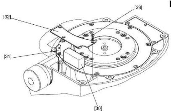
text_image
[32] [31] [29] [30]BATTERY TYPE: 9V, 6LR61 (PP3, 6AM6, MN1604, E-BLOCK) Vinten Part No. C550-023
Fig 7
Figures
text_image
[1] [3] [14] Volume 76 Fig 9Fig 9
text_image
[12] [12.1] [12.2] [12.3]Fig 10
text_image
[5] [4] [5.1] [5.2] 2/3 1/3 [4.1] [4.2][4.3]
Vector 75 Pan and Tilt Head
V4095-0001
CHINA
The Vitec Group plc China
Rm 706, Tower B
Derun Building
YongAn Dongli A No. 8
Jianwai Ave, Chaoyang District
Beijing, China 100022
Tel. +86 10 8528 8748
Fax +86 10 8528 8749
FRANCE
Vitec Group Videocom Division
Vitec Group Videocom Division
Gebäude 16
Planiger Straße 34
55543 Bad Kreuznach
Germany
Tel. +49 671 483 43 30
Fax +49 671 483 43 50
Vitec Group Videocom Division
Erfurter Straße 16
85386 Eching
Germany
Tel. +49 89 321 58 200
Fax +49 89 321 58 227
JAPAN
Vinten Japan KK
P.A. Bldg. 5F
3-12-6 Aobadai
Meguro-ku Tokyo 153-0042
Japan
Tel. +81 3 5456 4155
Fax +81 3 5456 4156
SINGAPORE
Vitec Group Videocom Division
6 New Industrial Road
02-02 Hoe Huat Industrial Building
Singapore 536199
Tel. +65 6297 5776
Fax +65 6297 5778
UNITED KINGDOM
Vitec Group Videocom Division
William Vinten Building
Western Way
Bury St Edmunds
Suffolk IP33 3TB, UK
Tel. +44 1284 752 121
Fax +44 1284 750 560
Sales Fax: +44 1284 757 929
USA
Vitec Group Videocom Division
709 Executive Blvd
Valley Cottage
NY 10989, USA
Tel. +1 845 268 0100
Fax +1 845 268 0113
Toll Free Sales: +1 888 2 Vinten
for more information, visit
www.vinten.com
Operators Guide
V4095-4980/2

Vinten™
A Vitec Group brand
Vinten