
Vision - Tripod Vinten - Free user manual and instructions
Find the device manual for free Vision Vinten in PDF.
User questions about Vision Vinten
0 question about this device. Answer the ones you know or ask your own.
Ask a new question about this device
Download the instructions for your Tripod in PDF format for free! Find your manual Vision - Vinten and take your electronic device back in hand. On this page are published all the documents necessary for the use of your device. Vision by Vinten.
USER MANUAL Vision Vinten
Vision blue Pan and Tilt Head
V4092-0001
EN
DE
ES
FR
IT
PT
JP
CN
Operators Guide
V4092-4980/2
Vinten
Vision blue
Pan and Tilt Head
Publication Part No. V4092-4980 Issue 2
English Page 4
Deutsch. . . . . . . . . . . . . . . . . . . . . . . . . . . . . . . . . . . . . . . . . . . . . . . . . . . . . . . . . . . . . . . . . . . . . . . . . . . . . . . . . . . Seite 15
Espanol .Pagina 31
Francais Page 47
Italiano.. .Pagina 63
Portugues . Pagina 77
日本語 93
中文 页码107
Copyright © 2011 The Vitec Group plc
All rights reserved throughout the world. No part of this document may be stored in a retrieval system, transmitted, copied or reproduced in any way, including, but not limited to, photocopy, photograph, magnetic or other record without the prior agreement and permission in writing of the Vitec Group plc.
Trademarks
Vinten™, Vision® and Quickfit® are registered trademarks of the Vitec Group plc.
Disclaimer
Information contained within this document is subject to change. Camera Dynamics Limited reserves the right, without notice, to make changes in equipment design or performance as progress in engineering, manufacturing or technology may warrant.
Published by
Vitec Group Videocom Division
Technical Publications Department
William Vinten Building
Western Way
Bury St Edmunds
Suffolk IP33 3TB
United Kingdom
Email: technical.publications@vitecgroup.com
Contents
Page
Safety - read this first 4
Usage. 4
Caring for the environment by recycling 4
Technical specification 5
Introduction and description. 7
Perfect Balance 7
Illuminated level bubble 7
Pan and tilt drag. 7
Pan and tilt brakes 7
Pan bar 7
Camera mounting 7
Operation 8
Fitting the pan bar 8
Installing the head on a tripod 8
Mounting the camera 8
Balancing the head 9
Operating the pan and tilt brakes. 10
Operating the pan and tilt drag 10
Maintenance 11
General 11
Cleaning. 11
Routine maintenance. 11
Replacing the battery 11
Adjusting the brakes levers and drag control knobs 12
Parts list 14
Safety - read this first
Warning symbols in this Operators Guide

Where there is a risk of personal injury or injury to others, comments appear highlighted by the word 'WARNING'—supported by the warning triangle symbol.
Where there is a risk of damage to the product, associated equipment, process or surroundings, comments appear highlighted by the word 'CAUTION'.
Usage
The Vision blue pan and tilt head is designed for use by professional camera operators to support and balance high-performance lightweight cameras and ancillary equipment weighing up to 5 kg (11 lb). The head must be mounted onto a suitable tripod designed to support the total payload.

WARNING!
- Do NOT attempt to use this product if you do not fully understand how to operate it.
- Do NOT use this product for any other purpose than that specified in this usage statement.
- Refer all maintenance beyond that detailed in this Operators Guide to an authorised Vinten service centre.
Caring for the environment by recycling
Disposal of waste batteries
Any batteries included with this product must not be treated as household waste. By ensuring these batteries are disposed of correctly, you will help prevent potentially negative consequences for the environment and human health, and help conserve natural resources. Hand the battery over to the applicable collection point for recycling waste batteries.
Technical specification
Weight (incl. pan bar, camera plate and bowl clamp assembly). 2.4 kg (5.3 lb)
Height (to mounting face) 12.1 cm (4.8 in)
Length 12.9 cm (5.1 in)
Width 14.8 cm (5.83 in)
Capacity range @ 55 mm C of G - See balance chart (Fig. 3) . . . . . . . . . . . . . . . . . . . . . . . . . . . . . . . . . . . . . . . . . . . . . . . . . . . . . . . . . . . . . . . . . . . . . . . . . . .
Tilt range. ± 90^
Pan range. 360°
Counterbalance fully variable Perfect Balance system
Tripod fixing 75 mm ball
Level bubble. illuminated, high contrast blue LED
Battery 12V
Vision blue front and left-hand side (Fig. 1)
[1] 1/4 in. screw and pin assembly
[2] Slide plate
[3] Tilt brake lever
[4] Pan brake lever
[5]. Tilt drag adjustment knob
[6]. Slide plate clamp
[7] Pan bar clamp
[8] Pan bar
Vision blue rear and left-hand side (Fig. 2)
[9] Platform
[10] Battery compartment
[11] Perfect Balance knob
[12] . Push button for illuminated level bubble
[13] .Pan drag adjustment knob
[14]. Bowl clamp assembly
[15] Illuminated level bubble
[16] Pan bar mount
[17]. Slide lock release
Introduction and description
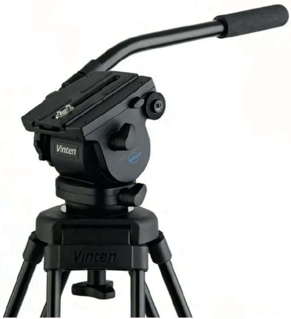
The Vision blue pan and tilt head has been designed to support and perfectly balance a range of professional digital video cameras. The head embodies an adjustable spring counterbalancing mechanism and LF drag assemblies for pan and tilt motions, and an adjustable camera mounting plate. The placement of the pan and tilt brakes, drag controls and counterbalance allows the operator to easily adjust the settings whilst operating the camera.
Perfect Balance
The balance system is adjusted using the Perfect Balance knob [11] located at the rear of the head. Maximum and minimum payloads that can be balanced, and the range of tilt angles achievable with the payload, are dependent on the weight of the camera payload, and on the camera's Centre of Gravity (C of G) height. The counterbalance chart (Fig. 3) shows the range of load and C of G height that can be maintained in balance. The shaded area of chart corresponds to those payload/C of G combinations that can be balanced over the full tilt range. The areas to the right indicate the progressively reducing tilt range with greater load and higher C of G. Where a payload/C of G combination falls outside of the chart range it will be necessary to increase or decrease the weight or the C of G height to enable the head to balance the load.
Pan and tilt drag
Both pan and tilt mechanisms incorporate the patented Vinten lubricated friction (LF) system to ensure smooth movement of the camera about these axes. Pan and tilt drag is adjusted using the pan drag adjustment knob [13] and tilt drag adjustment knob [5]. The whip-pan facility is unaffected by the pan drag setting.
Pan and tilt brakes
Both pan and tilt brakes allow each axis on the head to be locked at any chosen position. The pan brake lever [4] and tilt brake lever [3] are located on the left-hand side of the head.
Illuminated level bubble
Leveling the head is achieved using the level bubble [15]. In situations of low light, the level bubble can be illuminated by pressing the push button [12]. The bubble will remain illuminated for 15 seconds. The battery for the level bubble is contained within a battery compartment [10] located under the platform.
Pan bar
Pan bar mounting points [16] are located at the rear of the head on either side of the platform. The pan bar [8] is attached using a pan bar clamp [7], with angular adjustment available on the mount serrations. A fixed pan bar is supplied with an option to fit another pan bar, if required.
Camera mounting
The camera is attached to the head using a slide plate [2] that is attached to the camera and then loaded from the rear of the platform [9] and secured in position by the slide plate clamp [6]. The clamp prevents inadvertent removal of the camera from the head. The slide plate [2] is supplied with a 1/4 in. screw and pin assembly [1] and an additional 1/4 in. camera mounting screw to suit most lightweight digital video cameras.
Operation
Fitting the pan bar
A single pan bar is supplied and is fitted to either the right or left-hand side of the head onto the pan bar mounting [16].
To fit the pan bar:
Position the pan bar [8] on the pan bar mounting point [16].
Rotate the pan bar clamp [7] in a clockwise direction until the pan bar is secured.
A second pan bar can be fitted to the other side of the head, if required.
Installing the head on a tripod
The Vision blue pan and tilt head is supplied with an integral 75 mm ball mount, designed for installation onto a compatible Vinten tripod. Adaptors are available which enable the head to be installed on tripod fitted with other mountings.
To install the head onto the tripod:
Remove the bowl clamp assembly [14] from the head by turning it in a counter-clockwise direction.
Position the head on the tripod, carefully lowering the head into the tripod bowl.
Using the pan bar [8] to steady the head, refit the bowl clamp assembly [14] from below the tripod bowl, turning in a clockwise direction until the head is secured.
Apply the pan brake [4] and tilt brake [3] by turning the levers in a clockwise direction.
CAUTION! Do NOT use force on the brake levers. Hand tighten only.
Using the level bubble [15] adjust the position of the head until the head sits level in the tripod bowl. Tighten the bowl clamp assembly [14] to secure the head in position. The level bubble can be illuminated by pressing the push button [12].
Mounting the camera
The head is supplied with a camera slide plate [2], that can be fitted with a 1/4 in. screw and pin assembly [1] or two 1/4 in. camera screws dependant on the camera attachment.
To mount the camera onto the head, proceed as follows:
Remove the slide plate [2] from the head. Release the slide plate clamp [6] and press the slide lock release [17], then slide the plate out to the rear of the platform [9].
Attach the slide plate [2] to the camera or camera mounting plate under the approximate centre of the camera's weight.
Set the platform [9] level and apply both the pan and tilt brakes ([4], [3]).
CAUTION! Do NOT use force on the pan and tilt brake levers. Hand tighten only.
Lower the camera onto the rear of the platform [9] and slide the plate into the track in the platform, ensuring the slide lock release [17] snaps into position.
Using the pan bar [8] to steady the camera, tighten the slide plate clamp [6] in a clockwise direction to secure the camera in position.
Balancing the head
A perfectly balanced head allows operators to control camera movement with a minimal amount of effort. Once balanced, the head and its payload can be set to any tilt position and remain at that position, allowing operators to work hands-free.

WARNING!
- Do NOT exceed the maximum capacity of either the head or the tripod. The system will become unstable and may fail.
- Always support the camera payload when adjusting the Perfect Balance knob [11] to prevent it falling away suddenly.
- Keep hands clear of the moving platform to avoid trapping fingers.
Before balancing the head, ensure that the camera and lens, pan bar and all ancillary equipment has been fitted. The head must be balanced whenever the camera and/or lens is changed, or when ancillary equipment is added or removed.
To check camera balance, proceed as follows:

WARNING!
Steady the camera payload using the pan bar. Be prepared to prevent the head falling away suddenly.
Reduce tilt drag to a minimum level by turning the tilt adjustment drag knob [5] counterclockwise. Reduce the counterbalance to a minimum level by turning the Perfect Balance knob [11] in a counter-clockwise direction.
Hold the pan bar [8] to steady the camera payload. Release the tilt brake [3].
Tilt the head backwards and forwards to determine if the camera position is equally balanced in both directions. The camera and payload must be positioned over the C of G. If the C of G of the camera and head are not aligned, set the platform level and apply the tilt brake [3]. Position the camera correctly on the head by releasing the slide plate clamp [6] and then sliding the camera on the camera slide plate [2] backwards or forwards until it balances horizontally. Tighten the slide plate clamp [6] to secure the camera in position. Recheck and adjust as necessary.

WARNING!
Securely apply the slide plate clamp when the camera is positioned, to prevent the camera payload slipping.
Using the pan bar [8] to tilt the head backwards and forwards, turn the Perfect Balance lever [11] clockwise until the camera remains in position and does not fall away when the head is tilted and then released (hands-free).
Repeat the setup until perfect balance is achieved, when the camera remains set at any angle from +90^ to -90^ without falling away or springing back.
NOTE: Maximum tilt angle is less than 90^ for heavy payloads with a high C of G – refer to the counterbalance chart (Fig. 3).
Apply the tilt brake [3] to prevent the camera from moving accidentally when not in use.
Operating the pan and tilt brakes
Friction brakes on each axis allow the head to be locked at any chosen position. The operating levers for the pan brake [4] and tilt brake [3] are fitted on the left-hand side of the head.
CAUTION! Do NOT use force on the brake levers. Hand tighten only. Do NOT use the brakes to supplement drag, the head may be damaged. When the brakes are not in use, always ensure they are fully released.
To apply the brake turn the brake lever fully clockwise.
To release the brake turn the brake lever fully counter-clockwise.
Operating the pan and tilt drag
Both the pan and tilt mechanisms incorporate the Vinten LF system to ensure smooth movement of the camera about these axes. The tilt drag adjustment knob [5] is located at the front of the head on the right-hand side and the pan drag adjustment knob [13] is located on the rear of the head. Both drag adjustment knobs are provided with graduated scales.
NOTE: The whip-pan facility is not affected by the pan drag setting.
CAUTION! Reduce drag to a minimum when the head is out of use for long periods, to minimise wear on drag components.
To increase drag, turn the adjustment knob towards a higher graduation.
To decrease drag, turn the adjustment knob towards a lower graduation.
Maintenance
General
Vinten products are robustly made to high engineering standards and little attention is required to maintain serviceability except regular cleaning. Attention to the following points will ensure a long and useful service life with minimum need for repair. Do not make any adjustments to the head beyond those described in this manual. Should the product become defective, return the head to an authorised Vinten service centre.
Cleaning
During indoor use, the only cleaning required should be a regular wipe over with a lint-free cloth. Dirt accumulated during storage may be removed using a semi-stiff brush or vacuum cleaner. Particular attention should be paid to the ball mounting face of the head, the space between the tilting assembly and the base and the mounting bowl of the tripod.
CAUTION! Do NOT use solvent or oil-based cleaners, abrasives or wire brushes to remove accumulations of dirt, as these damage the protective surfaces. Use only detergent-based cleaners.
Use out-of-doors under adverse conditions will require special attention. Salt spray should be washed off with fresh clean water at the earliest opportunity. Sand and dirt acts as an abrasive and should be removed using a semi-stiff brush or vacuum cleaner.
Routine maintenance
During use, check the following:
Check the illumination of the level bubble. Replace battery, if necessary.
Check the effectiveness of the pan and tilt drag controls. Reset as necessary.
Check the effectiveness of the pan and tilt brakes. Reset as necessary.
No further routine maintenance is required.
Replacing the battery
(Fig. 4)
The battery illuminates the level bubble [15] when the push button [12] is pressed. The battery should be replaced yearly or whenever the illumination is considered inadequate.

WARNING!
If a payload is not fitted to the head, turn the Perfect Balance knob fully counter-clockwise to reduce the counterbalancing force before tilting the head forwards.
To replace the battery, proceed as follows:
Tilt the head forwards to allow access to the battery compartment [10]. Apply the tilt brake [3].
Using a thin-bladed screwdriver or similar tool, carefully remove the battery cover [10.1].
Remove the battery from the battery compartment [10].
Observing the correct polarity, insert the replacement battery [10.2] into the battery compartment [10].
Refit the battery cover [10.1].
Press the push button [12] and ensure that the level bubble [15] illuminates for approximately 15 seconds.
Adjusting the brakes levers and drag control knobs
The pan and tilt brakes levers ([3], [4]) and drag adjustment knobs ([5], [13]) may require adjustment after prolonged use. Only competent persons should undertake the adjustments of the drag controls. These adjustments can be made as part of regular servicing of the head. Contact an authorised Vinten service centre to discuss the servicing of your Vision blue pan and tilt head.
Pan and tilt brake lever adjustment
(Fig. 6) (Fig. 7)

WARNING!
Remove the payload before adjusting the pan brake lever. The pan and tilt brake levers are set during manufacture so that the brakes are fully applied before the levers reach their upper stops. As the brakes bed in during use it may be necessary to reset the levers.
To adjust the brakes levers, proceed as follows:
Turn the brake lever fully counter-clockwise to its lower stop (off position).
Using a flat-blade screwdriver or similar tool, unscrew the screw [19] securing the brake lever until its stop is reached.
Turn the lever approximately 15 degrees below the off position, then carefully pull the lever off the shaft [18].
Turn the brake shaft [18] clockwise by hand until the brake is fully applied (on position).
Turn the brake shaft counter-clockwise approximately 60 degrees.
Push the lever onto the brake shaft [18], turning the lever slowly counterclockwise until it fits into position (approximately 15 degrees).
Turn the lever clockwise to the off position and push it inwards.
Using the flat-blade screwdriver or similar tool tighten the securing screw [19]. Do not overtighten.
To test the brake, turn the lever clockwise and ensure that the brake is fully applied before the upper stop is reached. Then turn the lever fully counter-clockwise and ensure that the brake is fully released before the lower stop is reached. Re-adjust the position of the lever as necessary.
Drag knob adjustment
(Fig. 8)
The pan and tilt drag control knobs ([13], [5]) are set so that drag begins to be felt in the arrow area on the indicator [13.2].
To reset the drag knobs, proceed as follows:
Release the pan and tilt brakes.
turn the drag control knob [13] until the grab screw [13.1] is accessible. Using an Allen key slacken the grab screw by six turns.
Hold the indicator [13.2] stationary and slowly rotate the drag knob [13] 18 degrees to the left. 18 degrees is two clicks of the detent mechanism or half the pitch of the control knob lobes.
Using an Allen key, carefully tighten the grub screw [13.1], adjusting the position of the control knob as necessary so that the grub screw seats correctly in a slot in the indicator and can be fully tightened.
To test the adjustment, decrease drag to zero. Then increase drag and ensure that drag begins to be felt in the arrow area on the indicator [13.2] and that 9 on the indicator can be reached. Re-adjust the drag control until this can be achieved.
Parts list
The following lists include main assemblies, user-replaceable spare parts and optional accessories. For further information regarding repair or spare parts, please contact Vinten or your local Vinten distributor. For more information visit our website at www.vinten.com.
Main assemblies
Vision blue pan & tilt head . V4092-0001
Bowl clamp knob assembly 3330-30
Pan bar assembly (incl. clamp) 3219-110
User-replaceable spare parts
Bowl clamp knob assembly 3330-30
Brake Knob Assembly Kit. 3431-900SP
Slide Plate Assembly Kit V4043-1901
1/4 in. screw and pin assembly V4045-1006
1/4 in. camera screw V4045-2073
Battery (12V) C550-021
Optional accessories
Extended ENG slide plate assembly (incl. 3/8 in. camera screws) 3330-33
ENGQuickfit® automatic adaptor with wedge 3471-3
ENG Quickfit wedge 3763-11
Two-stage aluminium pozi-loc tripod 3819-3
Floor spreader 3363-3
Mid-level spreader V4032-0001
Set of three feet (for use with mid-level spreaders) 3378-902SP
Tripod carrying strap. 3425-3P
75 mm ball to 100 mm bowl adaptor 3330-243
Fixed pan bar 3219-110
Telescopic pan bar 3219-113
Soft case 3358-3
Inhalt
Seite
PRE-KEI'P#J#J#J#J#J#J#J#J#J#J#J#J#J#J#J#J#J#J#J#J#J#J#J#J#J#J#J#J#J#
The Vitec Group plc China
Rm 706, Tower B
Derun Building
YongAn Dongli A No. 8
Jianwai Ave, Chaoyang District
Beijing, China 100022
Tel. +86 10 8528 8748
Fax +86 10 8528 8749
FRANCE
Vitec Group Videocom Division
171 Avenue des Gréillons
92635 GENNEVILLIERS Cedex
France
Tel. +33 820 821 336
Fax +33 825 826 181
GERMANY
Vitec Group Videocom Division
Gebäude 16
Planiger Straße 34
55543 Bad Kreuznach
Germany
Tel. +49 671 483 43 30
Fax +49 671 483 43 50
Vitec Group Videocom Division
Erfurter Straße 16
85386 Eching
Germany
Tel. +49 89 321 58 200
Fax +49 8932158227
JAPAN
Vinten Japan KK
P.A.Bldg.5F
3-12-6 Aobadai
Meguro-ku Tokyo 153-0042
Japan
Tel. +81 3 5456 4155
Fax +81 3 5456 4156
SINGAPORE
Vitec Group Videocom Division
6 New Industrial Road
02-02 Hoe Huat Industrial Building
Singapore 536199
Tel. +65 6297 5776
Fax +65 6297 5778
UNITED KINGDOM
Vitec Group Videocom Division
William Vinten Building
Western Way
Bury St Edmunds
Suffolk IP33 3TB, UK
Tel. +44 1284 752 121
Fax +44 1284 750 560
Sales Fax: +44 1284 757 929
USA
Vitec Group Videocom Division
709 Executive Blvd
Valley Cottage
NY 10989, USA
Tel. +1 845 268 0100
Fax +18452680113
Toll Free Sales: +1 888 2 Vinten
Operators Guide
V4092-4980/2
for more information, visit
www.vinten.com