
EY6225 - Screwdriver PANASONIC - Free user manual and instructions
Find the device manual for free EY6225 PANASONIC in PDF.
| Product type | Cordless screwdriver (drill/driver) |
| Brand | Panasonic |
| Model | EY6225 |
| Screwing capacity | Wood screws: 3.8 × 38 mm; Metal screws: M2.5-M5 |
| Drilling capacity (metal) | 2 mm |
| Motor | DC 3.6 V |
| No-load speed | LOW: 200 rpm; HIGH: 600 rpm |
| Maximum torque | LOW: 4.4 Nm; HIGH: 1.5 Nm |
| Adjustable clutch torque | 21 positions, up to 3.0 Nm |
| Total length | 296 mm |
| Weight (with battery) | 0.5 kg |
| Battery type | Ni-Cd 3.6 V (model EY9025) |
| Standard charging time | Approximately 15 minutes |
| Charger | Model EY0225, electronic protection |
| Main functions | On/off, reverse switch, speed selector, 21-position clutch, switch lock |
| Manual use | Possible with switch on OFF (max torque 150 kg·cm) |
| Maintenance and cleaning | Dry and clean cloth; do not use water, solvent, or volatile cleaner |
| Safety | Switch lock, battery thermal protection, automatic stop at end of charge |
| Recycling | Battery recyclable; return to point of sale in Switzerland |
| Included accessories | Hexagonal drill bit adapter |
Frequently Asked Questions - EY6225 PANASONIC
User questions about EY6225 PANASONIC
0 question about this device. Answer the ones you know or ask your own.
Ask a new question about this device
Download the instructions for your Screwdriver in PDF format for free! Find your manual EY6225 - PANASONIC and take your electronic device back in hand. On this page are published all the documents necessary for the use of your device. EY6225 by PANASONIC.
USER MANUAL EY6225 PANASONIC
Operating Instructions
Bedienungsanleitung
Cordless Drill & Driver
Akku-Bohrschuber
natural_image
Line drawing of a handheld electronic device with ports and buttons (no text or symbols)Before operating this unit, please read these instructions completely.
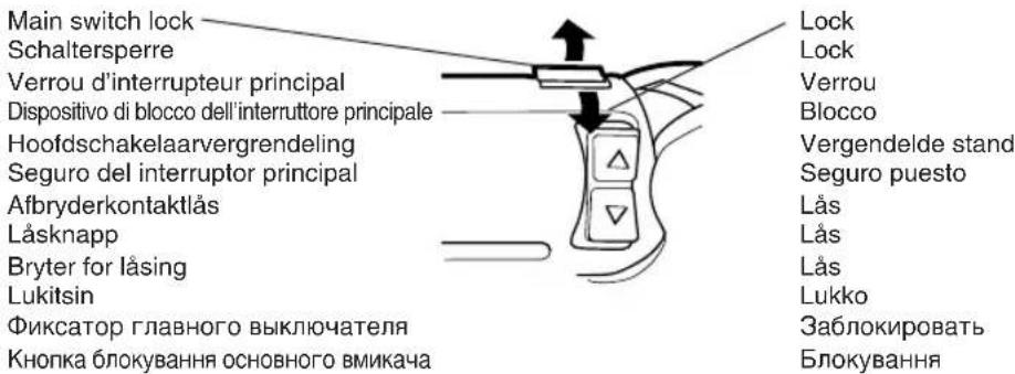
| (A) | Speed selector switchBereichsschalterSélecteur de vitesse de rotationSelettore di velocitàSnelheidskeuzeschakellarConmutador selector de velocidadHastighedsomskifterVarvtalsomkopplareHastighetsvelgerNopeudenvalintakytkinСелекторный переключатель скоростиПеремикач швидкості | (B) | Main switch lockSchaltersperreVerrou d'interrupteur principalDispositivo di blocco dell'interruttore principaleHoofdschakelaarvergrendelingSeguro del interruptor principalAfbryderkontaktlåsLåsknappBryter for låsingLukitsinФиксатор главного выключателяКнопка блокування основного вмикача |
| (C) | Main switchHaupschalterInterrupteur principalInterruttore principaleHoofdschakelaarInterruptor principalAfbryderkontaktFram/backomkopplareBryter for fremover/reversEteen/taakse valitsinГлавный выключательОсновний вмикач | (D) | Battery pack release buttonAkkupack-EntriegelungsknopfBouton de libération de batterieTasto di rilascio blocco batteriaAccu-ontgrendeltoetsBotón de liberación de la batería recargableUdløserknap til batteripakningBatteriets låsknapparBatteriets utløserknapperAkkupaketin irrotuspainikeetКнопка освобождения портативного батарейного источника питанияКнопка звільнення акумуляторів |
| (E) | Battery packAkkupackBatteriePacco batteriaAccuBloque de pilasBatteriBatteriBatteriAkkupakettiПортативный батарейный источник питанияАкумулятори | (F) | Clutch handleKuplungsgriffManche d'embrayageManopola dell'innestoKoppelhendelMango del embragueKoblingshåndtagMomentinställningClutch grepVääntövoiman säädinРукоятка захватаРукоятка затискного патрону |
| Hexagonal bit holderInnensechskantAdaptateur pour foret hexagonalStaffa di supporto della punta esagonaleZaskant bithouderPortabroca hexagonalBitholderBitshållare (insex)Holder for sekskantbitKuusisärmäterän pidinШестиугольный держатель сверлаШестикутний тримач насадок | (H)(G) | Bit setSchlagmeißel-SetJeu de mèchesAssortimento di punteBoorsetJuego de brocasBitplaceringBorrspetsuppsättningBits settTeräsarjaКомплект свёрлКомплект насадок | |
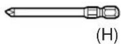
| (I) | Battery chargerLadegerätChargeur de batterieCaricabatterieAcculaderCargador de bateríasBatteriopladerBatteriladdareBatteriladerAkkulaturiЗарядное устройствоЗарядний пристрій | ||
2
3
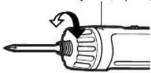
Set the scale at this line. Die skala an dieser Linie einstellen. Régler l'echelle sur ce trait. Impostare la scala su questa linea. Stel de schaal op deze lijn in. Ajuste la escala a esta linea. Indstil skalen ved denne linie. Ställ in skalan på den här lingen. Still inn skalaen etter denne lingen. Kuusi särmä terän pidin. Установите шкалу на эту линию. Встановить шкалу на цю риску.
natural_image
Diagram of a screwdriver with an arrow indicating rotation (no text or symbols)4
natural_image
Line drawing of a hand holding a tool with an arrow indicating rotation (no text or symbols)5
6
7
8
natural_image
Illustration of a hand holding a tool with directional arrows indicating movement or force (no text or symbols present)9
Battery pack
Akkupack
Batterie
Pacco batteria
Accu
Bloque de pilas
Batteri
Batteri
Batteri
Akkupaketti
To AC outlet
An Netzsteckdose
Read "Safety Instructions" booklet and the following before using.
I ADDITIONAL SAFETY RULES
1) Be aware that this tool is always in an operating condition, since it does not have to be plugged into an electrical outlet.
2) When drilling into walls, floors, etc., "live" electrical wires may be encountered. DO NOT TOUCH THE CHUCK OR ANY FRONT METAL PARTS OF THE TOOL! Hold the tool only by the plastic handle to prevent electric shock in case you drill into a "live" wire.
3) If the bit becomes jammed, immediately turn the main switch off to prevent an overload which can damage the battery pack or motor. Use reverse motion to loosen jammed bits.
4) During charging, the charger may become slightly warm. This is normal. Do not leave the battery in the charger for more than 24 hours after charging is completed.
5) Use only a dry, soft cloth for wiping the unit. Do not use a damp cloth, thinner, benzine, or other volatile solvents for cleaning.
6) Wear ear protectors when using the tool for extended periods.
II OPERATION
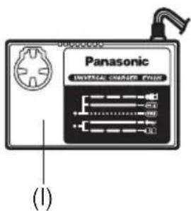
Hexagonal bit holder…(G)
- Attaching the bits (Fig. 2)
NOTE: When attaching or removing bit, be sure to set the main switch lock at the lock position.
- Hold the bit holder and pull it against the driver.
- Insert the bit into the hole of the drive shaft.
- The bit holder will return to its original position when released.
- Pull the bit to make sure it does not come out.
- To remove the bit, pull back on the bit holder in the same way.
Clutch handle…(F)
(Clutch Torque Setting)
Adjust the torque to one of the 21 possible settings to the job. There is an interval of about 0.13 Nm (1.3kg-cm or 1.1 in-lbs) between steps. (Fig. 3)
CAUTION! Test the setting before actual operation.
Reference for Adjusting Torque
| Scale | Torque Use | |
| 1 | Approx: 0.29 Nm(3.0 kgf-cm or 2.6 in-lbs) | For driving screws |
| 5 | Approx: 0.82 Nm(8.4 kgf-cm or 7.3 in-lbs) | |
| 9 | Approx: 1.35 Nm(13.8 kgf-cm or 12.0 in-lbs) | |
| 13 | Approx: 1.88 Nm(19.2 kgf-cm or 16.6 in-lbs) | |
| 17 | Approx: 2.41Nm(24.6 kgf-cm or 21.3 in-lbs) | |
| 21 | Approx: 2.94Nm(30.0 kgf-cm or 26.0 in-lbs) | |
| Approx: 4.4Nm(45.0 kgf-cm or 39.0 in-lbs) | For powerful driving screws and drilling |
- When use at high speeds, set the scale at 10 or below. (Operation stops at the maximum torque 1.5Nm (15kgf-cm), when the scale is higher.)
- The auto shut off function may become inoperable at use at higher scales when battery power drops. Recharge the battery in that case.
NOTE: The chart is only a reference. The torque setting may differ by materials, types of screws, etc. Please test it at your own conditions before use.
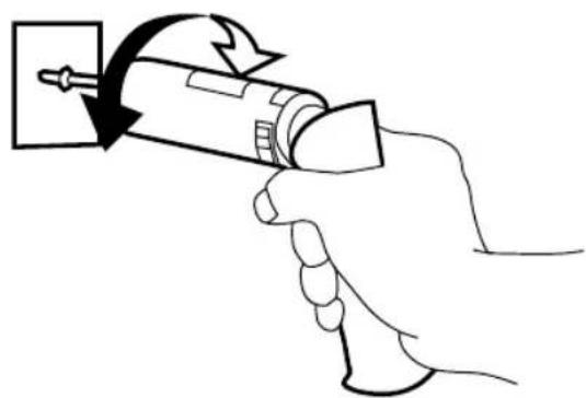
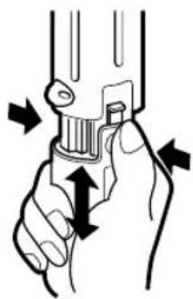
Bit locking function
With the switch at off, the bit is locked in place, and the tool can be used as a manual screw-driver - up to 14.7Nm (150kgf-cm, 130 in-lbs). There will be a little play in the driving shaft, but this is not a malfunction. (Fig. 4)
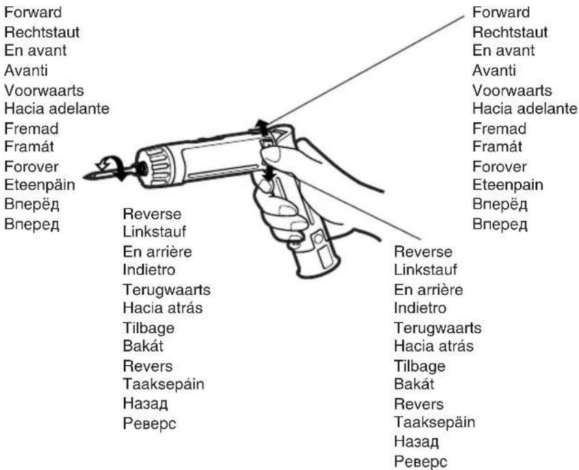
Main switch (ON/OFF)...(C)
Push the upper half of the switch for forward rotation, or the lower half for reverse rotation. (Fig. 5)
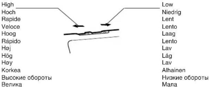
Speed selector switch…(A)
To suit the application of this tool, two different rotational speeds are available. Depending upon use, either the high or low speed should be selected.
| LOW | 200/min (RPM) | strong torque |
| HIGH | 600/min (RPM) | less torque |
CAUTION: Check rotational speed selection before operating this tool. (Fig. 6)
Main switch lock...(B)
After use, set the main switch lock at the lock position to prevent accidental operation. (Fig. 7)
Battery pack (EY9025)…(E)
CAUTION
- Press the battery pack release buttons on both sides and pull the pack away from the tool.
- Charge the battery pack using the battery charger.
- After the charging has been completed, remove the battery pack from the charger and connect it to the tool. Disconnect the charger form the power source when not in use. (Fig. 8)
Battery pack life
The rechargeable batteries have a limited life. If operation time becomes extremely short after recharging, replace the battery pack with a new one.
NOTE: • Use under extremely hot or cold conditions will reduce operating capacity per charge.
Battery Recycling
For environmental protection and recycling of materials, be sure that it is disposed of at an officially assigned location, if there is one in your country.
Battery charger...(I)
NOTE: When you charge the battery pack for the first time, or after prolonged storage, charge it for about 24 hours to bring the batteries up to full capacity.
EY0225
-
Plug the charger into an AC outlet. NOTE: Sparks may be produced when the plug is inserted into the AC power supply, but this is not a problem in terms of safety.
-
Insert the battery pack firmly into the charger. (Fig. 9)
-
During charging, the charging lamp will be lit. When charging is completed, an internal electronic switch will automatically be triggered to prevent overcharging.
- Charging will not start if the battery pack is warm (for example, immediately after heavy-duty operation). The orange standby lamp will be lit until the battery cools down. Charging will then begin automatically.
-
When charging is completed, the charging lamp will start flashing rapidly.
-
If a fully charged battery pack is inserted into the charger again, the charging lamp may light up and then flash slowly. After several minutes, the charging lamp may flash quickly to indicate the charging is completed.
-
If the charging lamp does not light immediately after the charger is plugged in, or if after the standard charging time the lamp does not go off, consult an authorized dealer.
NOTE:
- When a cold battery (of about 5°C or less) is to be charged in a warm room, leave the battery in the room for at least one hour and charge it when it has warmed up to room temperature. (Failing to do so may result in less than a full charge.)
- Cool down the charger when charging more than two battery packs consecutively.
CAUTION:
- Do not use power source from an engine generator.
- Unplug the charger when not in use.
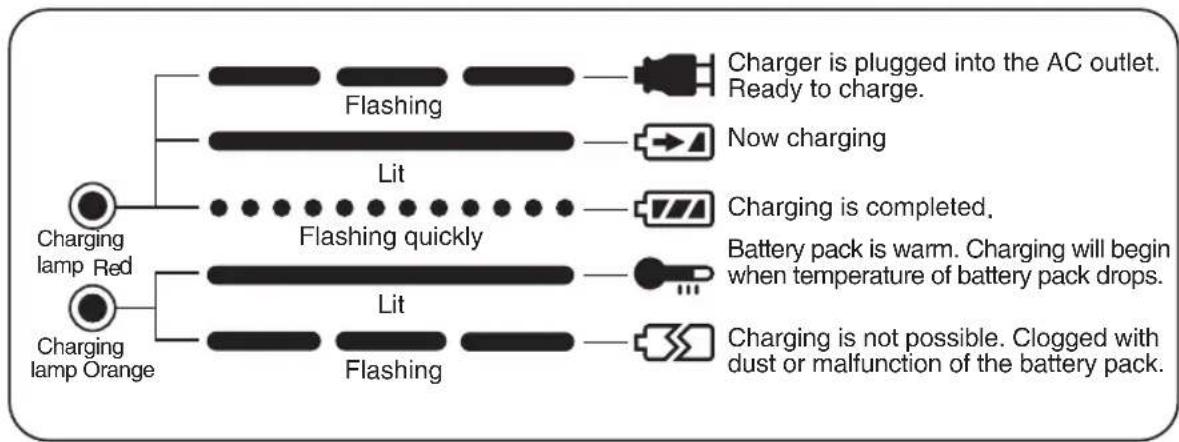
III LAMP INDICATIONS
flowchart
graph TD
    A["Charging lamp Red"] --> B["Flashing"]
    A --> C["Lit"]
    A --> D["Charging lamp Orange"]
    B --> E["Charger is plugged into the AC outlet. Ready to charge."]
    C --> F["Now charging"]
    C --> G["Charging is completed."]
    C --> H["Battery pack is warm. Charging will begin when temperature of battery pack drops."]
    C --> I["Charging is not possible. Clogged with dust or malfunction of the battery pack."]
IV Specifications
MAIN UNIT
| Model | EY6225 | ||
| Capacity | Screw driving | Machine screw | M2.5-M5 |
| Wood screw | 3.8 × 38mm (5/32'' × 1-29/64'') | ||
| Drilling | For metal | 2mm (5/64'') | |
| DC Motor 3.6VMotor | |||
| No load speed | LOW: 200/min (rpm)HIGH: 600/min (rpm) | ||
| Maximum torque | LOW: 4.4Nm (45kgf-cm, 39in-lbs)HIGH: 1.5Nm (15kgf-cm, 13in-lbs) | ||
| Maximum clutch torque | 3.0Nm (30kgf-cm, 26in-lbs) | ||
| Overall length | 296mm (11-21/32") | ||
| Weight (with battery pack) | 0.5kg(1.1lbs) | ||
BATTERY PACK
| Model (Battery type) EY9025 | |
| Storage Battery Ni-Cd Battery | |
| Battery voltage | 3.6V DC (1.2V × 3cells) |
BATTERY CHARGER
| Model EY0225 | |||
| Charging time | |||
| 2.4V 3.6V | Standard charging time | ||
| Approx: 15 minutesEY9021 EY9025 | |||
| Weight | 0.6kg (1.3 lbs) | ||
NOTE: For applicable battery packs to this charger, see the label on the charger or the latest general catalog.
ONLY FOR U.K.
ELECTRICAL PLUG INFORMATION
FOR YOUR SAFETY PLEASE READ THE FOLLOWING TEXT CAREFULLY
This appliance is supplied with a moulded three pin mains plug for your safety and convenience.
A 3 amp fuse is fitted in this plug.
Should the fuse need to be replaced please ensure that the replacement fuse has a rating of 3 amp and that it is approved by ASTA or BSI to BS1362.
Check for the ASTA mark 7 or the BSI mark 6 on the body of the fuse.
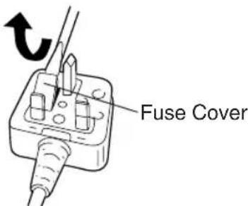
If the plug contains a removable fuse cover you must ensure that it is refitted when the fuse is replaced.
If you lose the fuse cover the plug must not be used until a replacement cover is obtained.
A replacement fuse cover can be purchased from your local Panasonic Dealer.
IF THE FITTED MOULDED PLUG IS UNSUITABLE FOR THE SOCKET OUTLET IN YOUR HOME THEN THE FUSE SHOULD BE REMOVED AND THE PLUG CUT OFF AND DISPOSED OF SAFELY. THERE IS A DANGER OF SEVERE ELECTRICAL SHOCK IF THE CUT OFF PLUG IS INSERTED INTO ANY 13 AMP SOCKET.
If a new plug is to be fitted please observe the wiring code as shown below.
If in any doubt please consult a qualified electrician.
IMPORTANT: The wires in this mains lead are coloured in accordance with the following code:
Blue: Neutral
Brown: Live
As the colours of the wire in the mains lead of this appliance may not correspond with the coloured markings identifying the terminals in your plug, proceed as follows. The wire which is coloured BLUE must be connected to the terminal in the plug which is marked with the letter N or coloured BLACK.
The wire which is coloured BROWN must be connected to the terminal in the plug which is marked with the letter L or coloured RED. Under no circumstances should either of these wires be connected to the earth terminal of the three pin plug, marked with the letter E or the Earth Symbol L.
How to replace the fuse: Open the fuse compartment with a screwdriver and replace the fuse and fuse cover if it is removable.
This apparatus was produced to BS800.
(Instelling draaimoment)
Interruptor principal (ON/OFF)…(C)
Fram/backomkopplare...(C)
| Skala | Moment Anvendelse | |
| 1 | Ca 0,29 Nm(3,0 kgf-cm or 2,6 in-lbs) | Skru inn skruer |
| 5 | Ca 0,82 Nm(8,4 kgf-cm or 7,3 in-lbs) | |
| 9 | Ca 1,35 Nm(13,8 kgf-cm or 12,0 in-lbs) | |
| 13 | Ca 1,88 Nm(19,2 kgf-cm or 16,6 in-lbs) | |
| 17 | Ca 2,41Nm(246 kgf-cm or 21,3 in-lbs) | |
| 21 | Ca 2,94Nm(30,0 kgf-cm or 26,0 in-lbs) | |
| Ca 4,4Nm(45,0 kgf-cm or 39,0 in-lbs) | For kraftig skru-eller borrearbeider |
Bryter for fremover/revers…(C)
Matsushita Electric Works, Ltd.
Osaka, Japan


- I ADDITIONAL SAFETY RULES
- II OPERATION
- Hexagonal bit holder…(G)
- Clutch handle…(F)
- (Clutch Torque Setting)
- Bit locking function
- Main switch (ON/OFF)...(C)
- Speed selector switch…(A)
- Main switch lock...(B)
- Battery pack (EY9025)…(E)
- CAUTION
- Battery pack life
- Battery Recycling
- Battery charger...(I)
- EY0225
- NOTE:
- CAUTION:
- III LAMP INDICATIONS
- IV Specifications
- ONLY FOR U.K.
- ELECTRICAL PLUG INFORMATION
- (Instelling draaimoment)
- Interruptor principal (ON/OFF)…(C)
- Fram/backomkopplare...(C)
- Bryter for fremover/revers…(C)
Brand : PANASONIC
Model : EY6225
Category : Screwdriver