
Gold 100 5G - Speaker MONITOR AUDIO - Free user manual and instructions
Find the device manual for free Gold 100 5G MONITOR AUDIO in PDF.
| Product type | Passive bookshelf speaker |
| Brand | Monitor Audio |
| Model | Gold 100 5G |
| Configuration | 2-way |
| High-frequency transducer | C-CAM ribbon, extension up to 60 kHz |
| Bass driver | 5.5 inch (14 cm) C-CAM cone |
| Midrange driver | Dedicated 4 inch (10 cm) C-CAM cone |
| Cone technology | RST® (reinforced rigidity), polymer chassis |
| Port technology | HiVe® port for dynamic bass |
| Cabinet construction | 20 mm MDF with internal bracing, curved profile |
| Finish | Dark walnut (real wood), gloss black, gloss white, gloss ivory |
| Grille | Magnetic attachment, removable |
| Connector type | Bi-wire terminals, Pureflow silver internal wiring |
| Crossover | High quality, polypropylene capacitors |
| Wiring functions | Single, bi-wiring, bi-amping |
| Included accessories | Plinth, spikes/feet, port plugs, grilles |
| Care and cleaning | Soft dry cloth, avoid abrasive products and solvents |
| Safety | Do not expose to moisture, place on a stable surface |
| Warranty | 5-year manufacturer warranty (online registration required) |
| After-sales service | Contact Monitor Audio via website |
Frequently Asked Questions - Gold 100 5G MONITOR AUDIO
User questions about Gold 100 5G MONITOR AUDIO
0 question about this device. Answer the ones you know or ask your own.
Ask a new question about this device
Download the instructions for your Speaker in PDF format for free! Find your manual Gold 100 5G - MONITOR AUDIO and take your electronic device back in hand. On this page are published all the documents necessary for the use of your device. Gold 100 5G by MONITOR AUDIO.
USER MANUAL Gold 100 5G MONITOR AUDIO
For Carpeted Floors 4
Grilles 4
Setting Up 5
2 Channel Positioning 5
AV Positioning 5
Setting up the Gold FX 6
Fixing the Gold FX to a wall 8
Connecting Speaker Cables 9
Bare Wire Connection 9
Banana Plugs 9
Wiring 9
Single Wiring 9
Bi-Wiring 10
Bi-Amping 10
The Effects of Bi-Wiring/ Bi-Amping 10
Portbungs 11
Specifications 12
Owner Information 13
Introduction
Born from the incredible success of the award winning GX Range, the new Gold Series further fine tunes its distinguished qualities featuring new advanced driver technologies and materials amalgamated to form a real world, yet truly esoteric speaker range. The Gold Series focuses on sonic clarity, detail and conveying a truly honest expression of a recorded piece. Wether it be the epic cinematic soundscapes presented in a movie, or the souring vocal melodies carried out by your favourite musical artist, the Gold Series will place you in the moment as if you were there.
This astounding attention to detail is not only evident the sound of the new Gold but in every component part, manufactured from only the finest materials and machined to exacting tolerances.
Main Features
- C-CAM® Ribbon transducer design - providing extension to a class leading 60kHz.
- New 5.5" and 6.5" bass drivers with C-CAM cone - larger piston area offering higher efficiency and better dynamics.
- New 4" dedicated mid-range driver with C-CAM cone and under-hung voice coil for very low distortion.
- New RST® Cone profile, for improved diaphragm rigidity and reduction in distortion.
- Die-cast Alloy chassis design for amazing rigidity and lower reflection properties.
- HiVe® port technology offers for smoother air-flow for a superior transient response and tighter bass.
- Single bolt through driver systems, for increased overall bracing, rigidity and driver/baffle de-coupling.
Die-cast alloy terminal panel arrangement with high quality bi-wire terminals and high end spade type, Pureflow® Silver link cables.
Pureflow Silver internal cabling. - High quality crossovers with premium grade Polypropylene film capacitors used throughout.
- Large radius cabinet edges provide low diffraction and smoother overall frequency response.
- Curved cabinet profile for increased rigidity and reduced internal standing waves.
- Hand selected premium quality wood veneer (dark walnut) or high gloss piano finishes (black, white or ebony).
Rigid 20mm MDF construction throughout, employing both radial and cross-bracing techniques for high rigidity and ensuring low cabinet colouration. - Invisible magnetic grille fixing offers clean visual styling when used without the grille.
Full 3-way design (Gold 200, 300 & Gold C350).
Die-cast alloy plinth structures and adjustable feet with provision for both hard and carpet floors (Gold 200 and 300 only).
Unpacking
Ensure there is plenty of clean floor area around where you are proposing to unpack the loudspeakers. Remove any lose components from the packaging (feet, bolts, plinths, grilles etc) and invert the carton. Lift the carton up and remove the packaging end cap. Remove the tape from the bag(s)revealing the bottom of the cabinet(s).
With the Gold 50 and Gold 100, stand the cabinets upright and remove the remaining packaging end cap and bag(s). Place the cabinets on the stands and position them according to instructions on page 5.
With the Gold 200 and Gold 300, fit the plinths and feet before proceeding any further.
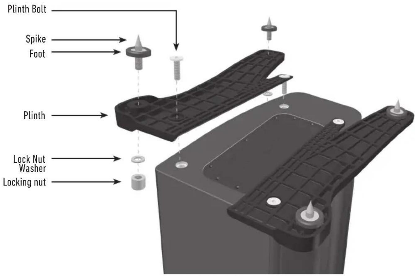
Plinth Fixing
(Gold 200 & 300 only)
Fit the plinths and spiked feet to the base of each speaker. Refer to page 4.
The plinths are provided for stability as well as improving the acoustic performance of the speakers. Due to the tapered shape of the cabinets, it is not recommended to install them without the plinths fitted as the speakers are likely to be unstable.
Spikes and Feet
For Wooden/Hard Floors
(Gold 200 & 300 only)
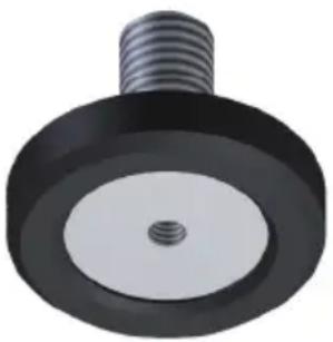
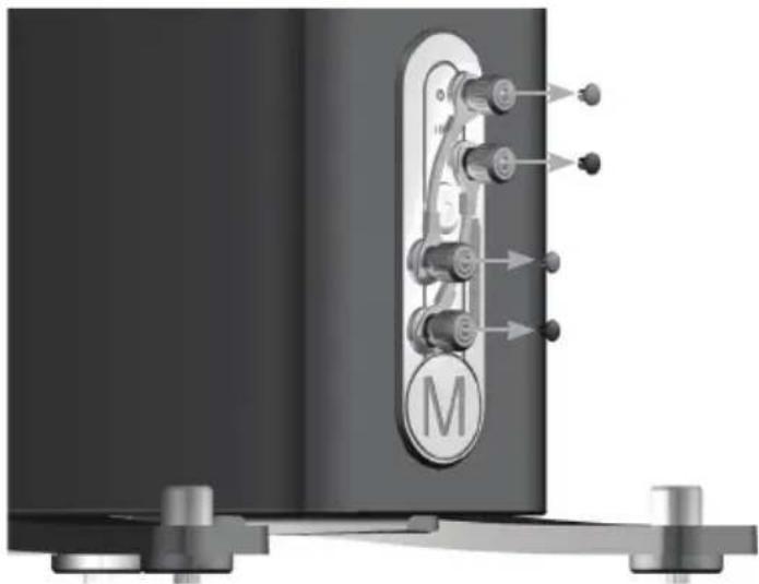
The foot comes pre-assembled for use on hard/solid floors or where spikes are inappropriate. All that is required is fixing them into the plinths. This is achieved by screwing the feet fully into the 2 threaded holes in each half of the plinth.
With great care turn the cabinet the right way up. Place the cabinet in the desired location, checking that it is level on all sides. If slightly off-level, unscrew the foot at the lowest point and check again. Continue this process until the cabinet is fully level. Use the locking nuts (illustrated on page 3) on each foot to fix the feet in place and to stop any unwanted vibrations.
For Carpeted Floors
(Gold 200 & 300 only)
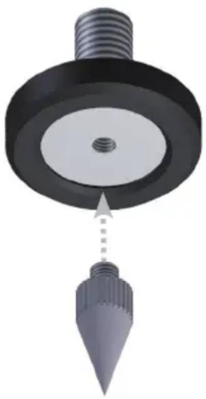
If being installed on carpeted floors, remove the spike from the packaging and fix it into the foot assembly, as illustrated.
Please ensure there are no hidden wires under the carpet that could be damaged by the spikes.
With great care turn the cabinet the right way up. Place the cabinet in the desired location, checking that it is level on all sides. If slightly off-level, unscrew the foot at the lowest point and check again. Continue this process until the cabinet is fully level. Use the locking nuts (illustrated on page 3) on each foot to fix the feet in place and to stop any unwanted vibrations.
Grilles
The grilles are held invisibly in place by magnets in the cabinet itself (except Gold FX).
When fitting, firstly ensure they are the correct orientation (badge at the bottom) and offer them up to the cabinet. The magnets should them pull them into position, but it may need some fine adjustment to ensure they are square on the cabinet.
The Gold FX comes with the grilles factory fitted. When removing them, carefully pris them away from the cabinet with the tips of your fingers. There are three separate grilles fitted to each Gold FX cabinet.

CAUTION: Always remove the grilles before attempting to move or lift the loudspeakers.
Setting Up
2 Channel Positioning
When arranging a 2 channel system, the listening position and the loudspeakers should form an equilateral triangle. The speakers should be positioned approximately 6 - 10 feet (1.8 - 3m) apart. The ideal distance from the rear wall varies depending on the speaker (see list below), however, they need to be a minimum of 3 feet (91cm) from the side walls.
Gold 50 and Gold 100 8 - 18 inches (20 - 45cm)
Gold 200 18 - 24 inches (45 - 60cm)
Gold 300 upto 36 inches (91cm)
Experimentation is strongly advised when initially setting up the speakers, as environment and personal preference differ with every installation. If there is insufficient bass for example, try moving your speakers closer to a wall. The opposite approach is recommended if there is excess bass. Also see the information on page 11 referring to Port Bungs. If stereo imaging is being lost, try 'toeing' them in slightly. The sound should appear to originate from the centre point between the speakers, not the actual speakers themselves.
AV Positioning
On pages 7 and 8, there are illustrations showing optimal positioning and some example room layouts for AV applications.
The front, and in some cases rear, floor standing and stand mount speakers should be positioned approx 6 - 9 feet apart (1.8m - 2.5m) and start with them about 10 inches (25cm) from the wall.
If the sound is too bass heavy or there is bass boom from the room when playing music (without a subwoofer), try moving the loudspeakers slightly further away from the wall(s) or adjusting the crossover frequency settings for the speakers and/ or sub. Also try changing the subwoofer's position. If this is not possible, then try the supplied port bungs (not included in the Gold FX or Centre). Refer to Page 11.
The Gold Centre channel should be positioned so they are pointing at the viewing position and at approximate ear height. If it is below or above ear height, use some rubber feet (small feet supplied) to angle it slightly.
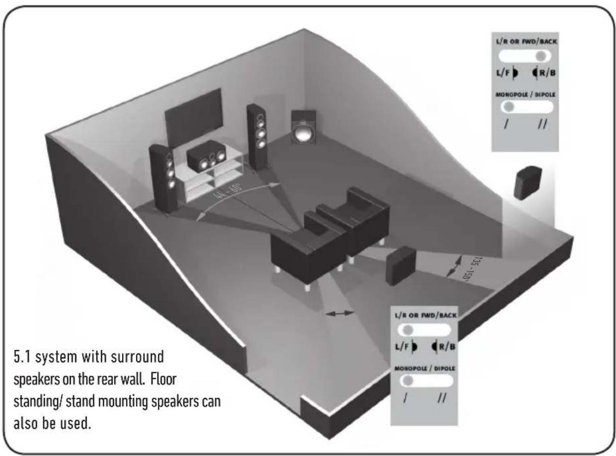
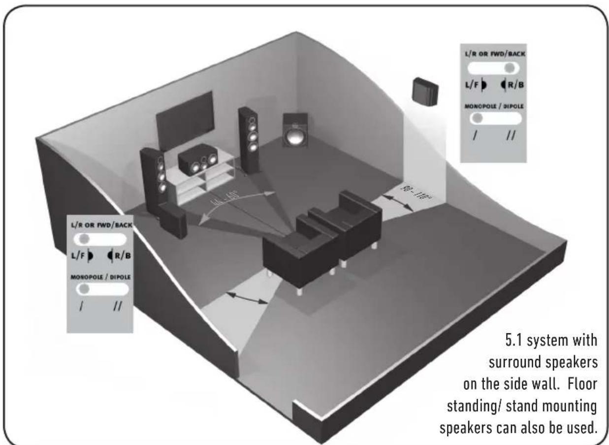
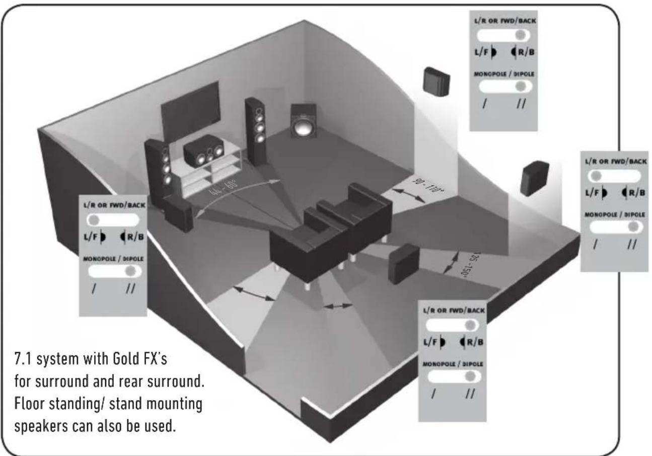
The Gold FX's should be positioned in accordance with the below illustrations and instructions, and approx 2 feet (60cm) to the bottom of the speaker above ear height when in your listening position.

NOTE: When using 2 pairs of Gold FX in a 7.1 system, set the rear surround left speaker to 'Right' and the rear surround right to 'Left'. This is required due to tweeter phasing. All four speakers need to be set to di-pole mode.
Setting up the Gold FX
The Gold FX's are independent speakers that can be tailored to be either left or right handed at the flick of a switch. Likewise, they can be operated in either di-pole or mono-pole modes. The default factory setting is mono-pole.
In mono-pole mode, only the main driver and tweeter will be active. In di-pole mode, the main tweeter is disengaged and the side drivers and tweeters are active. The front firing tweeters are out of phase with the other tweeter and mid/bass unit. It is recommended to implement this configuration when using two pairs Gold FX as part of a 7.1 channel system, with the Gold FX's taking up positions on side and rear walls. Please note, it is essential they are positioned correctly when used in a 7.1 channel system. Please refer to the switch positioning images on pages 7 and 8.

NOTE: Before adjusting any switches, please ensure that the amplifier is at the very least turned off. This will help to protect the amplifier.
Tweeter Attenuation Switch: This switch adjusts the level of the main high frequency tweeter unit. In the middle position, there is no attenuation. Placed in the - position, the high frequencies will be attenuated by 3dB. Placed in the + position, the high frequencies will be boosted by 3dB.
Location Switch: This switch is used when determining the location of the Gold FX's. Please refer to the illustrations on pages 7 & 8 for correct positioning. This will only make a difference when in 'di-pole' mode.
Mono-pole/ Di-pole Switch: This switch determines the actual mode of the Gold FX. When part of 5.1 systems as a rear speaker, set the switch to mono-pole. Although there is nothing wrong with experimenting and trying the switch in the di-pole mode. If part of a 7.1 system as side speakers, set the switch to di-pole. If using 4 Gold FX's (side and rear) set them all to di-pole mode. Please see the illustrations on pages 7 & 8 to determine the setting of the 'Location Switch' depending on system set up.
If you are using the 12v trigger, set the switch to monopole mode. The trigger will switch a relay to enable the di-pole mode.
12 volt Trigger: (Not shown) This feature is present on some AV amplifiers. It is possible to customise the 12v trigger to switch the speakers to di-pole for certain sources. For example, multi-channel music should be listened to in mono-pole mode, however, movies should be listened to in di-pole mode. This feature automates the switching between the two modes. Please refer to your AV amplifier manual for further instruction.

Fixing the Gold FX to a wall

CAUTION: Always determine where the Gold FX will be fixed and the structure of the wall. For safety reasons, if unsure of your ability to provide a secure and safe fixing, do not attempt to fix these speakers to a wall. Instead, please obtain the services of a competent and qualified trades person.

CAUTION: Ensure that water pipes or electricity cables do not run behind where the wall plate is going to be secured. Work from secure steps and avoid trailing wires.

NOTE: We do not supply wall fixing screws and plugs with the Gold FX. Please only use suitable fixings for the type of wall construction the Gold FX's will be fixed to.
To fix the Gold FX's to a wall, we would recommend using the wall fixing template provided within the packaging carton. Fix the wall plate to the wall, connect the speaker cables, and 12v trigger cables (if being used) and hang the cabinet on the wall plate.
Connecting Speaker Cables
Bare Wire Connection
Unscrew the binding posts and pass the bare wire through the through-hole. Tighten the binding post to clamp the wire in place.
Banana Plugs
Remove the red and black plastic plugs from the terminals and insert the banana plugs into the standard 4mm holes that are revealed. Pliers may be required to gain purchase on the plugs.
Wiring
Single Wiring
Single wiring is achieved via a single set of cables to the terminals on the back of the loudspeaker. Internally the loudspeaker crossover guides the frequencies to the appropriate driver/tweeter. Low frequencies to the bass drivers, mid frequencies to the mid/bass drivers and high frequencies to the tweeter.
It is perfectly acceptable to connect to the top, bottom terminals or even diagonally (experimentation is advisable to achieve the preferred results).

NOTE: When using this method you must KEEP the terminal links in place.
monitororaudio.com 9
Bi-Wiring
Bi-wiring is accomplished by connecting separate pairs of speaker cables to the terminals on the loudspeaker from a single pair of connections on the amplifier. In the case of the Gold Series, the bottom terminals connect to the bass driver(s) and the top terminals connect to the tweeter in 2 way loudspeakers, or the mid and tweeter in 2.5 and 3 way loudspeakers.

NOTE: When using this method the terminal links MUST be removed.

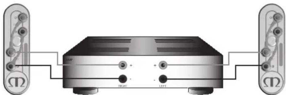
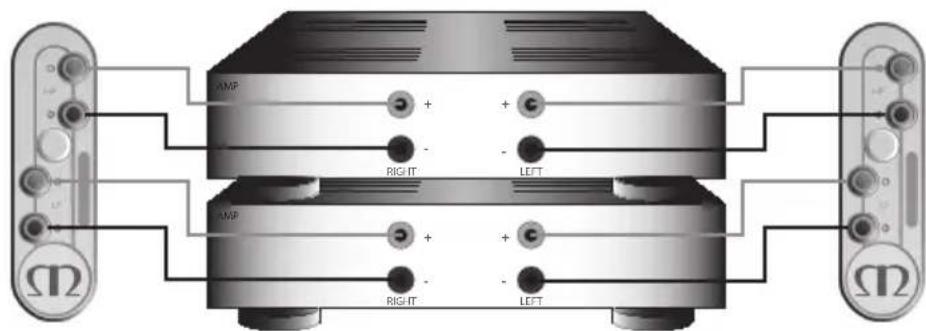
Bi-Amping
Bi-Amping is the same as Bi-Wiring except you are introducing a second amplifier into the equation.
In order to Bi-Amp you must connect a set of speaker cables to the top terminals on the loudspeaker from one amplifier and another set of speaker cables to the bottom terminals from the second amplifier.

NOTE: When wiring this method the terminal links MUST be removed.
The Effects of Bi-Wiring/ Bi-Amping
Fundamentally a loudspeaker crossover varies the impedance seen by the speaker and by the power amplifier. The situation is such that when the full range musical signal is applied to the terminals of a full-range speaker system, the bass driver(s) only receives low frequency signals, the mid driver receives the mid band frequency signals and the tweeter only gets sent high frequency signals. This means that if separate speaker cables are connected to the low frequency terminals, and the high frequency terminals, not only have the drive units and the frequency's directed and divided for them, but the two separate speaker cables will now also carry different signals, the bass cable mostly the lows, and the tweeter cable mostly the highs.
Once the high and low frequencies have been separated in this fashion, the strong current pulses and surges demanded by bass drivers when reproducing bass or drums, will not interact with the delicate sounds of a flute or cymbal.
In a single wired system, unwanted mechanical and electrical resonances manifest as distortion at both sets of speaker terminals. Due to the impedance of the speaker cables, these distortions will not be entirely cancelled by the amplifier. Instead, they modulate between the two crossovers, and degrade sound quality. When bi-wiring, this interaction is minimised as signal distortion is 'seen' at the amplifier's output where it can be more effectively cancelled. Bi-wiring/ bi-amping therefore presents a 'cleaner' signal at both the low frequency and high frequency speaker terminals, and because the high and low frequencies have already been separated, each has a minimal effect on the other - in essence the bass does not overpower delicate treble.
In terms of the audible benefit, bi-wiring/ bi-amping, provides more clarity and detail to the midrange and high frequencies. Often the bass will become faster and tighter. Focus and staging will improve as well. In all, this is a very effective and desirable improvement and is highly recommended by Monitor Audio.
Port bungs

WARNING: Care must be taken not to insert the port bungs too far into the port, as this may result in the foam bung being lost inside the cabinet.
If the loudspeaker is to be installed in a small room, typically 9 sqM (80 sqFT), or a room known to reproduce accentuated bass response, it may be desirable to fit port bungs. However, experimentation is recommended with positioning of the loudspeaker in the room prior to fitting. To optimise performance from the loudspeaker it is important to ensure the loudspeaker is not positioned too close to a wall or near the corners of a room (refer to the suggestions on page 5).
If the positioning of the loudspeaker is predetermined by room aesthetics or layout, or you find you have accentuated bass, please move on and read point 1 for the Gold 50/ Gold 100 and point 2 for the Gold 200/ Gold 300.
- Where stand-mount speakers (Gold 50 & Gold 100) are to be sited in close proximity (less than 8 inches/20cm) to a rear wall (such as on a bookshelf, positioned in a cabinet or on a stand close to a wall), we recommend fitting port bungs to the ports. This will reduce the bass 'boom' sometimes termed as overhang, and assist the loudspeakers to reproduce their best performance under these environmental conditions. 'Boom' is generally caused when bass energy from the loudspeaker 'excites' room modes and causes an accentuation at a particular frequency, or number of frequencies.
- Where floor-standing loudspeakers (Gold 200 & Gold 300) are to be sited in close proximity (closer than 18 inches/45cm) to a rear wall, we recommend fitting the port bungs. This will reduce the bass 'boom' sometimes termed as overhang and assist the loudspeakers to reproduce their best performance under these environmental conditions. This is caused when bass energy from the loudspeaker 'excites' room modes and causes an accentuation at a particular frequency, or number of frequencies.
When fitting port bungs the overall bass extension will not be reduced, however bass energy/ output around the port tuning frequency will be reduced. This has the effect of reducing bass 'boom' while increasing bass clarity and apparent agility.
In all circumstances experimentation is highly recommended.
| (2022)9192)6'LL | (2022)9192)6'LL | (2022)9192)6'LL | (2022)9192)6'LL | (2022)9192)6'LL | (2022)9192)6'LL | (2022)9192)6'LL | (2022)9181)5'LL | (2022)9191)5'LL | (2022)9191)5'LL | (2022)9191)5'LL | (2022)9191)5'LL | (2022)9191)5'LL | (2022)9191)5'LL | (2022)9191)5'LL | (2019)9191)5'LL |
| 8192x8192x9192x9192x9192x9192x9192x9192x9192x9192x9192x9192x9192x9192x9192x9192x9192x9192x9192x9192x9192x9192x100x100x100x100x100x100x100x100x100x100x100x100x100x100x100x100x100x100x100x100x100x100x100x100x100x101x100x100x100x100x100x100x100x100x100x100x100x100x100x100x100x100x100x100x100x100x100x100x100x100x102x100x100x100x100x100x100x100x100x100x100x100x100x100x100x100x100x100x100x100x100x100x100x100x100x110x100x100x100x100x100x100x100x100x100x100x100x100x100x100x100x100x100x100x100x100x100x100x100x100x111x100x100x100x100x100x100x100x100x100x100x100x100x100x100x100x100x100x100x100x100x100x100x100x100x112x100x100x100x100x100x100x100x100x100x100x100x100x100x100x100x100x100x100x100x100x100x100x100x100x1 | 8192x8192x9192x9192x9192x9192x9192x9192x9192x9192x9192x9192x9192x9192x9192x9192x9192x9192x9192x9187x9x1x1x1x1x1x1x1x1x1x1x1x1x1x1x1x1x1x1x1x1x1x1x1x1x1x1x1x1x1x1x1x1x1x1x1x1x1x1x1x1x1x1x1x1x1x1x1x1x1x1x3x1x3x3x3x3x3x3x3x3x3x3x3x3x3x3x3x3x3x3x3x3x3x3x3x3x3x3x3x3x3x3x3x3x3x3x3x3x3x3x3x3x3x3x3x3x3x3x3x3x3x3x4x4x4x4x4x4x4x4x4x4x4x4x4x4x4x4x4x4x4x4x4x4x4x4x4x4x4x4x4x4x4x4x4x4x4x4x4x4x4x4x4x4x4x4x4x4x4x4x4x4x5x5x5x5x5x5x5x5x5x5x5x5x5x5x5x5x5x5x5x5x5x5x5x5x5x5x5x5x5x5x5x5x5x5x5x5x5x5x5x5x5x5x5x5x5x5x5x5x5x5x6x6x6x6x6x6x6x6x6x6x6x6x6x6x6x6x6x6x6x6x6x6x6x6x6x6x6x6x6x6x6x6x6x6x6x6x6x6x6x6x6x6x6x6x6x6x6x6x6x6x5x5x5x5x5x5x5x5x5x5x5x5x5x5x5x5x5x5x5x5x5x5x5x5x5x5x5x5x5x5x5x5x5x5x5x5x5x5x5x5x5x5x5x5x5x5x5x5x5x3x3x3x3x3x3x3x3x3x3x3x3x3x3x3x3x3x3x3x3x3x3x3x3x3x3x3x3x3x3x3x3x3x3x3x3x3x3x3x3x3x3x3x3x3x3x3x3x3x5x5x5x5x5x5x5x5x5x5x5x5x5x5x5x5x5x5x5x5x5x5x5x5x5x5x5x5x5x5x5x5x5x5x5x5x5x5x5x5x5x5x5x5x5x5x5x5x5x4x4x4x4x4x4x4x4x4x4x4x4x4x4x4x4x4x4x4x4x4x4x4x4x4x4x4x4x4x4x4x4x4x4x4x4x4x4x4x4x4x4x4x4x4x4x4x4x4x3x3x3x3x3x3x3x3x3x3x3x3x3x3x3x3x3x3x3x3x3x3x3x3x3x3x3x3x3x3x3x3x3x3x3x3x3x3x3x3x3x3x3x3x3x3x3x3x3x8x8x8888888888888888888888888888888888888888888888888888888888888888888888888888888888888888888888888888 |
Owner Information
Product Details
Model
Product Serial No
Date of Purchase
Dealer Details
Dealer Name
Address
e-mail address
Telephone Number
Monitor Audio reserves the right to alter specifications without notice.
For the 5 years manufacturer's warranty, please visit the online registration form at:
www.monitoraudio.com
GOLD SERIES
manuelutilisateurs
Table des matieres
Introduction 16
| (2021992)6'LL | (2021992)6'6 | (2021992)6'7 | (2021992)6'8 | (2021992)6'9 | (2021992)6'10 | (2021992)6'11 | (2021992)6'12 | (2021992)6'13 | (2021992)6'14 | (2021992)6'15 | |
| 889×88SL×98Z189L×06C×0LE | 889×88SL×98Z189L×06C×0LE | 889×88SL×98Z189L×06C×0LE | 889×88SL×98Z189L×06C×0LE | 889×88SL×98Z189L×06C×0LE | 889×88 SL×98Z189L×06C×0LE | 889×88SL×98Z189L×06C×0LE | 889×88SL×98Z189L×06C×0LE | 889×88SL×98Z189L×06C×0LE | 889×88SL×98Z189 L×06C×0LE | (889)689PDS | |
| 889×88SL×98Z189L×06C×0LE | 889×88SL×98Z189L×06C×0LE | 889×88SL×98Z189L×06C×0LE | 889×88SL×98Z189L×06C×0LE | 889×98Z189L×06C×0LE | 889×98SL×98Z189L×06C×0LE | 889×98SL×98Z189L×06C×0LE | 889×98SL×98Z189L×06C×0LE | 889×98SL×98Z189L×06C×0LE | 889×98SL×98Z189 L×06C×0LE | (889)689PDS | |
| 889×88SL×98Z189L×06C×0LE | 889×88SL×98Z189L×06C×0LE | 889×88SL×98Z189L×06C×0LE | |||||||||
| 889×88SL×98Z189L×06C×0LE | 889×88SL×98Z189L×06C×0LE | 889×88SL×98Z189L×06C×0LE | |||||||||
| 889×88SL×98Z189L×05E×0LE | 889×88SL×98Z189L×05E×0LE | ||||||||||
| 889×88SL×98Z189L×05E×0LE | 889×88SL×98Z189L×05E×0LE | ||||||||||
| 889×88SL×98Z189L×05E×0LE | 889×88SL×05E×0LE | ||||||||||
| 889×88SL×98Z189L×05E×0LE | 889×88SL×05E×0LE | ||||||||||
| 889×88SL×98Z189L×05E×0LE | 889×88SL×98Z189L×05E×0LE | ||||||||||
| 889×88SL×98Z189L×05E×0LE | |||||||||||
| 889×88SL×98Z189L×05E×0LE | |||||||||||
| 889×88SL×98Z189L×05E×0LE | |||||||||||
| 889×88SL×98Z189L×06C×0LE | |||||||||||
| 889×88SL×98Z189L×06C×0LE | |||||||||||
| 889×88SL×98Z189L×06C×0LE | |||||||||||
| 889×88SL×98Z18 | |||||||||||
| 889×88SL×98Z18 | |||||||||||
| 889×88SL×98Z18 | |||||||||||
| 889×88SL×98Z18 | |||||||||||
| 889×88SL×05E×0LE | |||||||||||
| 889×88SL×05E×0LE | |||||||||||
| 889×88SL×05E×0LE | |||||||||||
| 889×88SL×05E×0LE | |||||||||||
| 889×8BSL×05E×0LE | |||||||||||
| 889×8BSL×05E×0LE | |||||||||||
| 889×8BSL×05E×0LE | |||||||||||
| 889×8BSL×05E×0LE | (8B)689PDS | ||||||||||
| 889×8BSL×05E×0LE | |||||||||||
| 889×8BSL×05E×0LE | |||||||||||
| 889×8BSL×05E×0LE | |||||||||||
| 889×8BSL×05E×0LE | 88 | 8 | 8 | 8 | 8 | 8 | 8 | 8 | (8B)689PDS | ||
| 889×8BSL×05E×0LE | |||||||||||
| 889×8BSL×05E×0LE | |||||||||||
| 889×8BSL×05E×0LE | |||||||||||
| 889×8BSL×05E×0LE | |||||||||||
| 889×8BSL×05E×0LE | |||||||||||
| 889×8BSL×05E×0LE | |||||||||||
| 889×8BSL×05E×0LE | |||||||||||
| 889×8BSL×05E×0LE | 8 | 8 | 8 | 8 | 8 | 8 | 8 | 8 | (8B)689PDS | ||
| 889×8BSL×05E×0LE | |||||||||||
| 889×8BSL×05E×0LE | |||||||||||
| 889×8BSL×05E×0LE | |||||||||||
| 889×8BSL×05E×0LE | 8 | 8 | 8 | 8 | 8 | 8 | 8 | 8 | (8B)689PDS | ||
| 889×8BSL×05E×0LE | |||||||||||
www.monitoraudio.com
GOLD SERIES
www.monitoraudio.com
GOLD SERIES
Manual del usuario
Índice
Introduccion 58
Caracteristicasprincipales 58
Desembalaje 59
| (2021.9.2) 6'LL | (2021.9.2) 6'6 | (2021.9.2) 9 | (2021.9.2) 2'ZZ | (2021.9.2) 2'ZZ | (2021.9.2) 6'6 | (2021.9.2) 5'4 | (sq) Bx Bx Bx Bx Bx Bx Bx Bx Bx Bx Bx Bx Bx Bx Bx Bx Bx Bx Bx Bx Bx Bx Bx Bx Bx Bx Bx Bx Bx Bx Bx Bx Bx Bx B× B× B× B× B× B× B× B× B× B× B× B× B× B× B× B× B× B× B× B× B× B× B× B× B× B× B× B× B× B× B× B× B× B× | |
| 8/9 x 8/9 x 9/9 x 9/9 x 9/9 x 9/9 x 9/9 x 9/9 x 9/9 x 9/9 x 9/9 x 9/9 x 9/9 x 9/9 x 9/9 x 9/9 x 9/9 x 9/9 x 9/9 x 9/9 x 9/9 x 9/9 x 100 × 100 × 100 × 100 × 100 × 100 × 100 × 100 × 100 × 100 × 100 × 100 × 100 × 100 × 100 × 100 × 100 × 100 × 100 × 100 × 100 | 8/9 x 8/9 x 9/9 x 9/9 x 9/9 x 9/9 x 9/9 x 9/9 x 9/9 x 9/9 x 9/9 x 9/9 x 9/9 x 9/9 x 9/9 x 9/9 x 9/9 x 9/9 x 9/9 x 9/9 × 100 × 100 × 100 × 100 × 100 × 100 × 100 × 100 × 100 × 100 × 100 × 100 × 100 × 100 × 100 × 100 × 100 × 100 × 100 × 10 | 8/9 x 8/9 x 9/9 x 9/9 x 9/9 x 9/9 x 9/9 x 9/9 x 9/9 x 9/9 x 9/9 x 9/9 x 9/9 x 9/9 x 9/9 x 9/9 x 9/9 x 9/9 x 9/9 x 9/8 × 100 × 100 × 100 × 100 × 100 × 100 × 100 × 100 × 100 × 100 × 100 × 100 × 100 × 100 × 100 × 100 × 100 × 100 × 100 × 101 × 100 × 100 × 100 × 100 × 100 × 100 × 100 × 100 × 100 × 100 × 100 × 100 × 100 × 100 × 100 × 100 × 100 × 100 × 100 × 10 8/9 x 8/9 x 9/9 x 9/9 x 9/9 x 9/9 x 9/9 x 9/9 x 9/9 x 9/9 x 9/9 x 9/9 x 9/9 x 9/9 x 9/9 x 9/9 x 9/9 x 9/9 x 9/9 x 9/9 x 8/9 x 8/9 x 9/9 x 9/9 x 9/9 x 9/9 x 9/9 x 9/9 x 9/9 x 9/9 x 9/9 x 9/9 x 9/9 x 9/9 x 9/9 x 9/9 x 9/9 x 9/9 x 9/9 x 9/9 × 8/9 x 8/9 x 9/9 x 9/9 x 9/9 x 9/9 x 9/9 x 9/9 x 9/9 x 9/9 x 9/9 x 9/9 x 9/9 x 9/9 x 9/9 x 9/9 x 9/9 x 9/9 x 9/9 x 9/9 8/9 x 8/9 x 9/9 x 9/9 x 9/9 x 9/9 x 9/9 x 9/9 x 9/9 x 9/9 x 9/9 x 9/9 x 9/9 x 9/9 x 9/9 x 9/9 x 9/9 x 9/9 x 9/9 x 9/9 |
www.monitoraudio.com
GOLD SERIES
| (2021)972)6'LL | (2021)972)6'6 | (2021)972)6'6 | (2021)972)6'6 | (2021)972)6'6 | (2021)972)6'6 | (2021)972)6'6 | (2021)972)6'6 |
| 859×85SL×95Z189×06C×0LE | 859×85Z2×0L09×189×95Z | 859×85Z2×0L09×189×95Z | 859×85Z2×0L09×189×95Z | 859×85Z2×0L09×189×95Z | 859×85Z2×0L09×189×95Z | 859×85Z2×0LE | (859)859×H859×H859×H859×H859×H859×H859×H859×H859×H859×H859×H859×H859×H859×H859×H859×H859×H859×H859×H859×H859× |
| 859×9×85SL×95Z109×06C×0LE | 859×85Z2×0L09×189×95Z | 859×85Z2×0L09×189×95Z | 859×85Z2×0L09×189×95Z | 859×85Z2×0L09×189×95Z | 858×85Z2×0L09×189×95Z | 858×85Z2×0LE | (858)858×H858×H858×H858×H858×H858×H858×H858×H858×H858×H858×H858×H858×H858×H858×H858×H858×H858×H858×H858×H858× |
| 859×9×85SL×95Z×Z109×06C×0LE | 859×85Z2×0L09×189×95Z | 859×85Z2×0L09×189×95Z | 859×85Z2×0L09×189×95Z | 859×85Z2×0L09×189×95Z | |||
| 859×9×85SL×95Z×Z109×06C×0LE | 859×85Z2×0L09×189×95Z | 859×85Z2×0L09×189×95Z | 859×85Z2×0L09×189×95Z | 859×066-08-08-08-08-08-08-08-08-08-08-08-08-08-08-08-08-08-08-08-08-08-08-08-08-08-08-08-08-08-08-08-08-08-08 | 859×859×H859×H859×H859×H859×H859×H859×H859×H859×H859×H859×H859×H859×H859×H859×H859×H859×H859×H859×H859× | 859×859×H859×H859×H859×H859×H859×H859×H859×H859×H859×H859×H859×H859×H859×H859×H859×H859×H859×H859× | (859)859×H859×H859×H859×H859×H859×H859×H859×H859×H859×H859×H859×H859×H859×H859×H859×H859×H859×H859 |
| 859×9×85SL×95Z×Z109×06C×0LE | 859×85Z2×0L09×189×95Z | 859×85Z2×0L09×189×95Z | 859×85Z2×0L09×189×95Z | 859×96-08-08-08-08-08-08-08-08-08-08-08-08-08-08-08-08-08-08-08-08-08-08-08-08-08-08-08-08-08-08-08-08-0 | |||
| 859×9×85SL×95Z×Z109×06C×0LE | 859×85Z2×0L09×189×95Z | 859×85Z2×0L09×189×95Z | 859×85Z2×0L09×189×95Z | 860-08-08-08-08-08-08-08-08-08-08-08-08-08-08-08-08-08-08-08-08-08-08-08-08-08-08-08-08-08-08-08-08-08 - | |||
| 859×9×85SL×95Z×Z109×06C×0LE | 859×85Z2×0L09×189×95Z | 859×85Z2×0L09×189×95Z | 859×85Z2×0L09×189×95Z | 840-08-08-08-08-08-08-08-08-08-08-08-08-08-08-08-08-08-08-08-08-08-08-08-08-08-08-08-08-08-08-08-08-0 | (859)859×H859×H859×H859×H859×H859×H859×H859×H859×H859×H859×H859×H859×H859×H859×H859×H859×H859×H859 × | ||
| 859×9×85SL×95Z×Z109×06C×0LE | 859×85Z2×0L09×189×95Z | 859×85Z2×0L09×189×95Z | 859×85Z2×0L09×189×95Z | 840.06-08-08-08-08-08-08-08-08-08-08-08-08-08-08-08-08-08-08-08-08-08-08-08-08-08-08-08-08-08-08-08-08-0 840.06-08-08-08-08-08-08-08-08-08-08-08-08-08-08-08-08-08-08-08-08-08-08-08-08-08-08-08-08-08-08-08 - |
Gegevens eigenaar
Productinformation
Model
Product serialummer
Aankoopdatum
www.monitoraudio.com
GOLD SERIES
用户手册
目录
引言 100
主要特征 100
拆箱 101
底座安装 101
长钉和撑脚 102
适用于木质/硬地板 102
适用于地毯地板 102
格栅 102
安装 103
双波段定位 103
AV定位 103
GOLD FX 的安装 104
Gold FX在墙面的固定 106
扬声器电缆的连接 107
裸线连接 107
香蕉插头 107
线路 107
单布线 107
双布线 108
双功放 108
双布线/双功放的效果 108
端口塞 109
用户信息 111
引言
Gold 50 and Gold 100:20-45 cm
Gold 200:45-60 cm
Gold 300:do91cm
Pn noDroTOBKe K 3KcNlyaTaun HAcToaTeNbHO peKomeHdyem N03KcnepmEnHpObaTb, NoCKoNbKy ONMaIbHbIe XapaKtepncTNKn dnn pa3hblx cnyaTeJe HNDNBduaIbHbI. Ecn, HApnpMep, Ha cnyx HeIOCTaTOUHO bACOB, nonpo6yIte nepMeCtNTb KOLOHK 6nXke K CTeHe. Ecn 6acbl qpe3MepHbI, cdeNaTe HaobopoT. Kpme TOrO, npouTne Ha cTpaHnce 123 INΦopMaunIO, kacaOuYoc3 aRnywek nopTob. Ecn yTpauH cTepeoo6pa3, nonpo6yIte HEmHoro pa3BepHyTB akCyTueckne cNCTeMb IOBHytpb. 3Byk DoJxeh BOCPNHIMATbcKaK nCXoJaun m3 ueTpaJIbHoTouKn MeJy AC, a He n3 camnx AC.
MHorokHaJIbHaCnCTema
Innocpaun Ha ctp. 119 n 120 noka3bBAOT onTumalbHoe pa3MeueHne n KOHfhypaun nomeeHn dI npocnyuBaHn I npocMoTa ayDno-BuDeo KOHTHa.
ΦpoHTaJIbHbIe I B HeKOTOpbIX CnyaX TbIOBbI AC DoJXHbI paCnOJaTbCra Ha paCCToHmN npUMePHO 1.8 - 2.5 M npyr ot dpura KAK MNHMym B 25 cm OT CTehbl.
Ecn npn Bocnpo3BeHnn My3bKn 3Byk nepenacbiueh 6acamn nn B KOMhate rehepnpyeTc H3K0aactOThtb ryn, nonpo6ynte nepemecntb KOIOHKn noaIbwe ot cTeH nn OTpeYnnpoBaTb qactoty Cpe3a KpoccoBepa akyctnecknx cnTeM n ca6Byepa. Nonpo6ynte n3MeHnTb pacnoJoxHe nce 6byepa. Ecn 3TO HeBO3MOxHo, nonpo6ynte BCTaBnTb B faoHHBepTophble nopTb npnilaraemblc 3arlyuKN (cm. ctp. 123).
Akyctnuecka cnctema ceHtpaIbHoro KaHana doJxHa paCnoIaratbca TaK, yTo6bI OHa, haxOJaB B none 3peHna HappaBHeHa npAmo Ha BaN HaxOdInacb pPImepHo Ha Bbcote ywe. Ecn OHa haxOJTc HnXe IIN BblSe, BocNoIb3yITeCb He6OJIbShIMn pe3HHOBbIMn onopAMn, yTo6bI HemHoro ee HaKJIOHTb B Ty IIN dpyrHy o CTOpOny.
KoONKn Gold FX dONXHbI 6bITb paCNOJoxeHb I B COOTBeTCTBn C npNBedeHHbIMn Hxke nllIOCTpaunm INHCTpyKcunMn npImepHo Ha 60 cm Bblwe ypOBHa ywe cnyataTeN.

| JX 6''L | JX 6''G | JX 9 | JX 2''L | JX 2''G | JX 6''G | JX 6''L | JX 8''G |
| WV 09E X 185 X 45Z | WV 09E X 185 X 45Z | WV 09E X 185 X 45Z | WV 09E X 185 X 45Z | WV 09E X 185 X 45Z | WV 09E X 185 X 45Z | WV 09E X 185 X 185 | WV 09E X 185 X 185 |
| WV 09E X 185 X 45Z | WV 09E X 185 X 45Z | WV 09E X 185 X 45Z | WV 09E X 185 X 45Z | WV 09E X 185 X 45Z | WV 09E X 185 x 185 | WV 09E X 185 X 185 | WV 09E X 185 X 185 |
| WV 09E X 185 X 45Z | WV 09E X 185 X 45Z | WV 09E X 185 X 45Z | WV 09E X 185 x 185 | WV 09E X 185 x 185 | WV 09E X 185 x 185 | WV 09E X 185 x 185 | WV 09E X 185 x 185 |
| WV 09E X 185 X 45Z | WV 09E X 185 X 45Z | WV 09E X 185 X 45Z | WV 09E X 185 x 185 | WV 09E X 185 x 185 | WV 09E X. 185 x 185 | WV 09E X 185 x 185 | WV 09E X 185 x 185 |
| WV 09E X 185 X 45Z | WV 09E X 185 X 45Z | WV 09E X 185 X 45Z | WV V09E X 185 X 45Z | WV 09E X 185 X 45Z | WV 09E X 185 X 185 | WV 09E X 185 x 185 | WV 09E X 185 x 185 |
| WV 09E X 185 X 45Z | WV 09E X 185 X 45Z | WV 09E X 185 X 45Z | WV 09E X. 185 X 45Z | WV 09E X. 185 X 45Z | WV 09E X. 185 X 185 | WV 09E X. 185 x 185 | WV 09E X. 185 x 185 |
| WV 09E X 185 X 45Z | WV 09E X 185 X 45Z | WV 09E X 185 X 45Z | WV 09E X. 185 X 45Z | WV 09E X. 185 X 45Z | WV 09E X. 185 x 185 | WV 09E X. 185 x 185 | |
| WV 09E X 185 X 45Z | WV 09E X 185 X 45Z | WV 09E X 185 X 45Z | WV 09E X. 385 X 45Z | WV 09E X. 185 X 45Z | WV 09E X. 185 X 185 | WV 09E X. 185 x 185 | WV 09E X. 185 x 185 |
| WV 09E X 185 X 45Z | |||||||
HOpMaunI0JIb3OBaTeJIA
CbeHn8 o6 n3eenn
MoeIb
CepnHbI Homep
Даразаджи
CbeHnO npoDaBue
Ha3BaHne
Ampes
TenefoH
KoMaHnra Monitor Audio coXpaHЯET 3a cObO npaBO n3MeHЯr TExHnueckne xapaKeTepnKu 6e3 npedBapntelbHoro yBeDOMleHn.
3aperntpuyte npno6peHoe n3dene Ha caite www.monitoraudio.com.

Monitor Audio Ltd.
24 Brook Road
Rayleigh, Essex
SS67XJ
England
Tel: +44 (0)1268 740580
Fax: +44 (0)1268 740589
Email: info@monitoraudio.co.uk
Web: www.monitoraudio.com
Designed and Engineered in the United Kingdom Made in China
2014. Version 1
- Introduction
- Main Features
- Unpacking
- Plinth Fixing
- Spikes and Feet
- For Wooden/Hard Floors
- For Carpeted Floors
- Grilles
- Setting Up
- Channel Positioning
- AV Positioning
- Setting up the Gold FX
- Fixing the Gold FX to a wall
- Connecting Speaker Cables
- Bare Wire Connection
- Banana Plugs
- Wiring
- Single Wiring
- Bi-Wiring
- Bi-Amping
- The Effects of Bi-Wiring/ Bi-Amping
- Port bungs
- Owner Information
- Product Details
- Dealer Details
- GOLD SERIES
- Table des matieres
- Índice
- Gegevens eigenaar
- Productinformation
- 目录
- 引言
- MHorokHaJIbHaCnCTema
- HOpMaunI0JIb3OBaTeJIA
- CbeHn8 o6 n3eenn
- CbeHnO npoDaBue
Brand : MONITOR AUDIO
Model : Gold 100 5G
Category : Speaker